3.9 Piezoelectric Energy Conversions
3.9.1 Introduction
Power harvesting using piezoelectric material is a technique that can be useful to power remote or inaccessible sensors. For any location where only a relatively short cable must be drawn, power harvesting is not an option because the engineering and material cost required to develop a power harvester may be significant. This technique is strictly limited to remote use for sensor systems and needs special electronic circuits for generating useful power efficiently.
Applications will range from the nano-Watt to the Watt range, with the latter requiring in the order of 20–30 cubic cm of piezo material. Piezo materials do not possess the energy-density potential to compete with more traditional large-scale means of generating electricity. Some applications are depicted in Figure 3.9.1.
Figure 3.9.1 Applications of power harvesting using piezoelectric material. (a) Vortex shedding in a water flow (Taylor, 2001), (b) impress of an insole in a shoe (Kymissis et al., 1998), and (c) motion of a backpack (Feenstra, Granstrom, and Sodano, 2008)

3.9.2 Piezoelectric Material
Introduction
Since its discovery by the Curie brothers in 1880, piezoelectric materials have held the interest of the scientific community for their electro-mechanical properties. Researchers have shown that this class of material has intrinsic properties suitable for actuation as well as power-harvesting applications. The actuation is especially suitable for applications that require a fast response and a large bandwidth (Chopra, 2002). Nevertheless, some characteristics need to be overcome by a thoughtful design of piezoelectric components to achieve the desired force and displacement for actuation.
Piezoelectric materials have also the property to convert mechanical energy into electrical energy. When such a material is subjected to a strain, an electrical charge is created inside the material. This property is called the direct piezoelectric effect. Additionally, when the material is subjected to an electrical field, it deforms according to the electrical field magnitude. This is called the converse piezoelectric effect.
Piezoelectric Constants
A piezoelectric material is characterized by the piezoelectric strain constant dij, which relates the strain to the electrical field. The subscript i indicates the direction of the applied electrical field, and the subscript j indicates the direction of the deformation. Prior to use, the piezoelectric material is poled. The material is heated up to its Curie temperature while an electrical field is applied. Above the Curie temperature, electrical dipoles present in the material get aligned with the electrical field. This causes the piezoelectric effect. Consequently, if a material is heated back to its Curie temperature, it will lose its piezoelectric ability as the dipoles will revert back to their initial random distribution. Conventionally the poling direction is along the vertical axis (3-axis) (Figure 3.9.2). When an electrical field (E) is applied in the poling direction, the material is contracting in that direction and extending in other directions (1- and 2-axis). Changing the direction of the electrical field will result in a contraction along the 1- and 2-axis and extension along the vertical axis. To quantify those piezoelectric effects, the direct and shear strains relate to the electrical field in the following way:
(3.9.1) 
Figure 3.9.2 Axis reference system for piezoceramic components and piezoelectric effects for an electrical field applied in the poling direction
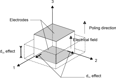
where E1, E2, and E3 are the components of the electrical field; and ε1, ε2, and ε3 and γ23 and γ13 are, respectively, the strain and shear components. A deformation along the 1- and 2-axis that is characterized by the d31 coefficient is called the d31 effect, and a deformation along the 3-axis is called the d33 effect as the d33 coefficient characterizes this deformation (Figure 3.9.2).
Power Consumption
The power consumed by a piezoelectric actuator to achieve a sinusoidal drive of the actuator depends on the capacitance of the device, the operating frequency, and the driving voltage signal. The average power consumed is equal to the average current that flows through the piezoactuator multiplied by the applied voltage (Physik Instrumente, 2009). This is an approximation as it does not take into consideration any loss in the electromechanical system.
Average current passing through the actuator (A):
(3.9.2) ![]()
Average power consumption (W):
(3.9.3) ![]()
Peak power consumption (W):
(3.9.4) ![]()
where f is the driving signal frequency (Hz), Cpiezo is the piezoactuator capacitance (F), and Vp is the driving signal peak voltage (V).
Losses
The power required does not take into account the losses inside the material. Piezoelectric materials are converting electrical energy into mechanical energy and many phenomena during that process can account for their loss in efficiency (Mezheritsky, 2004):
- Induced shear actuator.
- Electric loss.
- Dielectric loss.
- Mechanical loss.
- Elastic loss.
- Piezoelectric loss.
These losses strongly depend on the operation mode of the piezoelectric actuators. Once the actuator is charged, the energy required to keep the obtained deformation is small. The losses are much more important when the material is subjected to a harmonic voltage. These losses come from the hysteresis of the piezoelectric material (Damjanovic, 2006). The energy losses are dissipated with heat. Their importance depends on various factors. Physik Instrumente (2009) states that in large signal condition, the losses can reach up to 12% of the power used to actuate the piezoelectric actuator.
Bandwidth and Actuation Speed
Piezoelectric materials are known to have a large bandwidth that makes them suitable for ultrasonic transducers. The time required for a piezoelectric actuator to reach its nominal displacement depends on the resonance frequency. According to Physik Instrumente (2009), the minimum rise time on a piezoelectric actuator is a third of the period corresponding to the resonance frequency given that the controller can deliver the necessary current in the actuator.
Piezoceramics
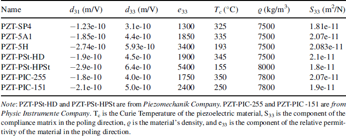
Piezoceramics have been widely studied and have been used since the Second World War to manufacture ultrasonic transducers. This material is polycrystalline and needs to be subjected to high electrical fields in order to be poled and to demonstrate electromechanical properties. During this process, the various crystalline cells inside the materials orientate themselves according to the direction of the electrical field. Piezoceramics achieve high force with low strain. When integrating piezoceramic components into a structure, the stresses subjected by the material must be carefully investigated as piezoceramic material will fail for very low uniaxial tensile stresses. Table 3.9.1 lists some piezoceramic materials with their properties. For piezoceramic materials d31 = d32 and d24 = d15.
Table 3.9.1 Table of some piezoceramic materials. PZT-SP4 and PZT-5A1 are from Smart-Material Company. PZT-5H is taken from Chopra (2002)
Piezo Polymers
Polyvinylidene fluoride (PVDF) is the main polymer that exhibits a significant piezoelectric effect. Like any piezoceramic material, the constants d33 and d31 characterize the electromechanical properties of the material. Unlike piezoceramics, piezopolymer does not have shear electromechanical coupling and d31 is not equal to d32. Prior to the poling process, the polymer is stretched in order to align the carbon chains. The dipole on the chains is pointing in the direction normal to the applied stress. The polymer is then subjected to heat and an large electrical field (Atkinson, 2006). At room temperature the amorphous part of the polymer is over its glass transition temperature (32°C), therefore the polymer is flexible at room temperature. It is possible to find flexible transducers among the commercial products made with PVDF polymer.
Unfortunately, the performance of the polymer is far behind that of piezoceramic material (Table 3.9.2). The force and displacement are hence lower for the same applied voltage.
Table 3.9.2 Comparison of the piezoelectric coefficients of PZT-5H piezoceramic and PVDF piezopolymer. The figures are taken from Chopra (2004)

3.9.3 Power Harvesting
Introduction
As explained in Section 3.9.2, piezo plates or stacks deform when a voltage is applied. This mode is called the actuator mode as it is used to generate a displacement in the mechanical domain. The opposite is also possible: Mechanical straining of the material will lead to the generation of electrical charge or voltage, called the sensing mode. This is done by connecting a very high electrical resistance across the piezo element in order to prevent much electrical current from flowing. The developed voltage is then a measure for the mechanical deformation of the piezo material.
It is also possible for the piezo element to actually generate electricity from a mechanical input, current as well as voltage. By affixing a sheet of piezo material to a deforming/or vibrating structure, it will deform with the structure. The piezo will then convert the mechanical vibration energy to electrical current. By conducting this current through a resistor, a voltage difference will be created due to Ohm's law: U = IR. Then, through the equation P = UI, the power can be calculated. Machines provide the mechanical excitation in the form of a harmonic load, unbalance of rotating parts, or straining of the frame. Examples of power-harvesting research using periodic excitations are impacts, fluid structure interaction (Barrera-Gil, Alonso, and Sanz-Andres, 2010), walking humans (Kymissis et al., 1998), and (Feenstra, Granstrom, and Sodano, 2008) wind or current around blunt bodies (Taylor et al., 2001).
The example of connecting only a resistor across the electrodes of figure 3.9.3 is to demonstrate the power-harvesting concept. To actually generate useful power for sensors and other electronics will require more advanced methods such as synchronous electric charge extraction, synchronized switch harvesting on inductor, pre-biasing, and so on. These will be addressed briefly in this section.
Basic Concepts for a Single Degree of Freedom Piezo Electric Model
Let us consider a 1 degree of freedom (DOF) system consisting of a mass M, mechanical stiffness k, and damping c. There is also a piezo element with properties kp and Θ, which represent the material stiffness, and a piezo electric coupling value (unit: N/V). Consider the fundamental piezo equations (Priya and Inman, 2009):
(3.9.5a) ![]()
(3.9.5b) ![]()
In this equation ε, SE, σ, d, E, D, and εσ represent the mechanical strain, the compliance matrix (the inverse of the stiffness matrix), the mechanical stress, the piezo electric constant, the electrical field, the charge displacement (the integral of current density), and the permittivity of the material, respectively. If we are to assume a one-dimensional stress state (1D loading) and an actual piece of piezo material with finite dimensions, we can rewrite these equations (here we assume use of the 31 mode) to
(3.9.6a) ![]()
(3.9.6b) ![]()
In this equation, kp, u, Θ, V, F, Cp, and I represent the mechanical piezo stiffness, displacement, electromechanical coupling, voltage, applied force, capacitance, and current flowing from the piezo, respectively. Lastly, we want to include the dynamics of this system by introducing mass (M) and damping (C):
Figure 3.9.3 Ideal physical model of a 1DOF system
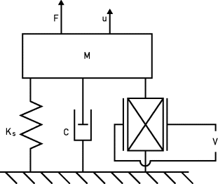
The ideal physical model of this system is given in Figure 3.9.3.
Equation 3.9.7a represents the mechanical force balance. We recognize the traditional damped oscillator consisting of the mass M, damping C, and stiffness K. The latter consists of the piezo stiffness and, depending on the model, also some structural stiffness (![]() ). Through the piezoelectric effect, the piezo element will also generate a force of ΘV. Equation 3.9.7b represents the electrical domain, more specifically a balance of electrical currents at the piezo contacts. Here we see that the current generated by the piezoelectric effect is Θu. Some current is lost to the internal capacitance of the piezo element, which adheres to the equation of a capacitor I = CdU.
). Through the piezoelectric effect, the piezo element will also generate a force of ΘV. Equation 3.9.7b represents the electrical domain, more specifically a balance of electrical currents at the piezo contacts. Here we see that the current generated by the piezoelectric effect is Θu. Some current is lost to the internal capacitance of the piezo element, which adheres to the equation of a capacitor I = CdU.
For a conceptual discussion, we will consider the system with a resistor R, rectifier, and buffer capacitor Cs, known as direct current impedance matching (DCIM). The rectifier is an electronic device consisting of four diodes that is capable of converting the alternating current from the piezo element to a direct current that is more suitable for sensors and electronics. Together with the buffer capacitor Cs and properly tuned electric load R, a harmonic excitation of the system will lead to a nearly constant rectified voltage Vdc allowing for a constant dissipation of energy in the resistor. Figure 3.9.4a shows the circuit layout, and Figure 3.9.4b conceptually shows the alternating piezo voltage Vp under a given displacement u. Ideally the resulting constant voltage Vdc is equal to the maximum Vp. Two modes of operation can be seen in the voltage curve. Between t1 and ti, the piezo element is transitioning from −Vdc to +Vdc and no current is flowing from the piezo element. Between time ti and t2, the voltage remains constant and current is flowing from the patch. Shu and Lien (2006) provide a detailed analytical description of the circuit. For most, cases this circuit possesses a single optimal resistance, written as
(3.9.8) ![]()
Figure 3.9.4 DCIM circuit layout and typical waveforms
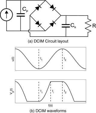
With a lower resistance, more current will flow but at a lower voltage. With a higher resistance, less current will flow but at a higher voltage. Recalling P = UI, it is not either the voltage or current that must be optimized, but the product. Let us also consider some other properties of the circuit. The electromechanical coupling Θ tells us how much force is generated for 1 V in the piezo material. The important question is how this “apparent stiffness” relates to the mechanical stiffness of the system. This is indicated with the variable ke (Shu and Lien, 2006):
(3.9.9) ![]()
Looking ahead, note that the equation for ![]() is valid only at the optimum resistance. The coupling
is valid only at the optimum resistance. The coupling ![]() , in combination with the damping ratio
, in combination with the damping ratio ![]() , is the most critical in the analysis of a power-harvesting system (Shu and Lien, 2006). For low values (
, is the most critical in the analysis of a power-harvesting system (Shu and Lien, 2006). For low values (![]() ), the influence of the generated piezo voltage on the mechanical domain is negligible. Analyzing the behavior of the 1DOF system under a harmonic excitation is then straightforward: First the mechanical domain is solved without taking the piezo material into account. The resulting displacement is then inserted into equation (3.9.7b) and solved for V.
), the influence of the generated piezo voltage on the mechanical domain is negligible. Analyzing the behavior of the 1DOF system under a harmonic excitation is then straightforward: First the mechanical domain is solved without taking the piezo material into account. The resulting displacement is then inserted into equation (3.9.7b) and solved for V.
This leads to the first important property for efficient power-harvesting systems. Maximizing the displacement of the harvester leads to more generation of charge from the piezo element. For ambient vibrations, it is therefore important to tune the harvester's natural frequency to the ambient vibration frequency. This maximizes the amplitude of the harvester. As the coupling ![]() and the ratio
and the ratio ![]() increase, the piezo material becomes more dominant in the system. The dynamic behavior of the mechanical domain becomes dependent on the amount of piezo material, the electrical load resistance, and so on. This requires that both equations must be solved simultaneously.
increase, the piezo material becomes more dominant in the system. The dynamic behavior of the mechanical domain becomes dependent on the amount of piezo material, the electrical load resistance, and so on. This requires that both equations must be solved simultaneously.
The natural frequency will, for instance, shift as well. Assuming an optimally matched load, the change in frequency for a DC impedance matched system is written as follows (Shu et al., 2006):
(3.9.10) ![]()
with ωem denoting the (now coupled) electromechanical natural frequency of the system. Another issue is that one may install so much piezo material that the total power output of the harvester will actually decrease (Lefeuvre et al., 2005). There is clearly an optimum amount of material. A qualitative description of this phenomenon is analogous to that of the optimal load resistance: No piezo material will result in zero harvested power but a large vibration. As the amount of material is increased, the power output will increase as well. When too much piezo material is added, it will provide so much damping that the harvester will not achieve a large enough vibration level.
Resonant versus Nonresonant Systems
In the previous section, it was stated that resonant systems are most efficient. At resonance a small input force will lead to a large displacement because energy is efficiently transferred from the input force to the harvester. There are, however, some applications in which this may be impossible, such as very high-force applications. Although not as prevalent, there are some applications (De Jong, 2012) that generate enough useful power simply due to the large force or strain present.
These applications are typically subresonant or displacement driven, as opposed to force driven. For displacement-driven systems, the dynamics clearly become irrelevant with respect to the power-harvesting calculation. For subresonant systems, the frequency of actuation is far lower than the natural frequency of the component. This also greatly simplifies analysis because a quasi-static approach can be used when calculating the deformation of the system, again ignoring the dynamics of the mechanical domain. Damping and natural frequencies can be ignored as well.
In subresonant systems, most of the energy from the input is transferred to strain deformation of the host structure and released again as the force or deformation decreases. This is why these systems are very inefficient from an energy standpoint. This does not mean that subresonant power-harvesting systems do not generate useful energy, but that they convert only a smaller amount of the available mechanical energy present to electrical energy.
A final critical difference for resonant systems is that, regardless of which circuit is used, the maximum achievable output remains the same. The main difference is that the amount of piezo material that is required varies with the more efficient circuits requiring less material. In displacement-driven systems, the more efficient circuits increase the output significantly for the same amount of piezo material (Lefeuvre et al., 2006).
Alternative Electrical Circuits
The impedance matching circuit is the first circuit that was developed for power harvesting but it is comparatively inefficient. Considering Figure 3.9.4 the material is not conducting any energy out of the piezo element for a significant portion of one oscillation. For an optimally designed circuit, it transfers current for only 50% of the time, between ti and t2. Much time is lost while the piezo element must change voltage between +Vdc and −Vdc to again conduct energy through the rectifier. A number of nonlinear methods have been developed to greatly increase the output of harvesting systems.
These methods require active circuits to control switches within the circuit in order to manipulate the piezo voltage. These circuits will, of course, need to be powered by the piezo element as well. This means that for micro-scale harvesters, the output may be so small that it is not wise to use active circuits: the added output of the circuit may be fully consumed by the control electronics. The active circuits become viable options when the output of the DCIM circuit is in the order of mW or more. An example is the synchronous electric charge extraction (SECE) circuit proposed by Lefeuvre et al. (2005). This circuit (see Figure 3.9.5) functions by breaking the contact between the piezo element and the rest of the circuit. Contact is made only when the circuit detects a maximum in the piezo voltage after which the energy stored in the piezo element is rapidly discharged through the remainder of the circuit. For the same displacement excitation of the mechanical domain, this circuit will generate approximately four times more power than the DCIM circuit. For resonant systems, the SECE circuit requires only a quarter of the amount of material that DCIM requires. The advantage is the lack of an optimum resistance.
Figure 3.9.5 SECE circuit layout and typical waveforms
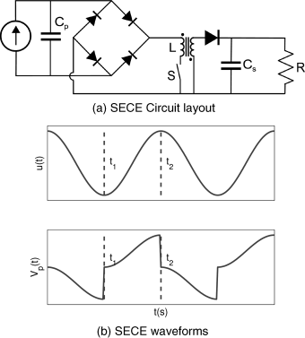
Another circuit is the synchronized switch harvesting on inductor (SSHI) circuit. For more information on this circuit, see Guyomar et al. (2005).
3.9.4 Conclusions
Power harvesting using piezoelectric material is a technique that can be useful to power remote or inaccessible sensors. For any location where only a relatively short cable must be drawn, power harvesting is not an option because the engineering and material cost required to develop a power harvester may be significant. This technique is strictly limited to remote use for sensor systems and needs special electronic circuits for generating useful power efficiently.
The energy balance must also be considered. In some cases, adding a power harvester somewhere in a system (e.g., a drive train, vehicle, or rotating equipment) may increase the load on the motor and as a consequence the energy consumption of the system. No energy is then actually harvested but more conversions take place, greatly reducing efficiency. Power harvesting must not be seen as a technique to generate a significant amount of power. Applications will range from the nano-Watt to the Watt range, with the latter requiring in the order of 20–30 cubic cm of piezo material.
Notes
1. According to Dutch standards, Rsi = 0.13 m2 K/W for a vertical wall being part of the thermal shell (NNI, 2001).
2. According to Dutch standards, Rcavity = 0.18 m2 K/W for a heat flow in an (almost) unventilated cavity (NNI, 2002).
3. According to Dutch standards, Rse = 0.04 m2 K/W for a vertical wall being part of the thermal shell (NNI, 2001).
4. The current manufacturers for EV batteries are Shin Kobe Machinery in collaboration with Hitachi Maxwell (with Nissan equipping these EV batteries), Japan Storage Battery, Matsushita Batteries Industrial Co. Ltd, JSB high-energy cells for EV, Panasonic, and NGK Insulators. All these rechargeable batteries are based on the combination of an insertion compound versus an insertion compound.
