D.2 An Overview of Selection Strategies
To give the designer more insight into the world of (alternative) power sources, this section will review tools and methods in which different power and energy sources are compared. Different search and selection strategies are applicable during the concept development phase:
In the rest of Section D.2, these strategies will be described more in depth.
D.2.1 Power Source Selection Tools
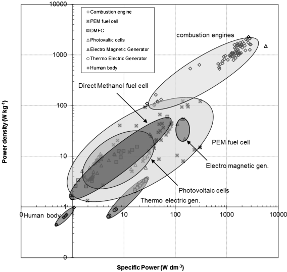
Four main aspects of power sources for portable electronics are of interest for the designer: capacity and power per unit of (1) size, (2) weight, and (3) costs. Flipsen (2006) compared alternative power sources among each other based on these aspects. A large database of commercially available power and energy sources and combinations thereof is used to compare them as shown in Figure D.2.1. Due to its restriction to commercially available products, opportunities for short-term but especially long-term developments in portable power sources are overlooked. Emerging power sources like FCs are found to be an interesting alternative to lithium-ion batteries. Other power sources described and compared are ether-smog, human power, thermoelectric generators, piezo generators, electromechanical devices, photovoltaic cells, micro fuel cells, and micro combustion engines.
Figure D.2.1 The power density versus specific power for different alternative power sources

Fu et al.'s (2005) “Database and Selection Method for Portable Power Sources” is based on the “free search” selection strategy for materials and processes from Asby et al. (2004), and is implemented in the Cambridge Engineering Selector (CES, 2009). The CES selection tool is widely used by industrial designers to screen thousands of materials and production processes for their applicability to a specific product, part, or function. The search engine of CES is a “free search” selection method, one of three possible selection strategies available (Asby et al., 2004):
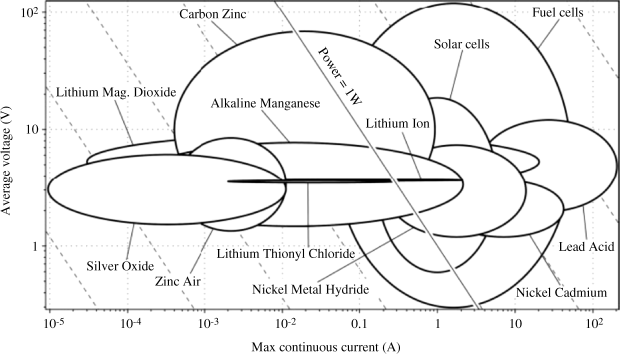
The CES power source selector is mainly based on basic characteristics such as the mass m, volume V, and cost c of existing components. In Figure D.2.2, an example is given of the output of the power source selection method. Besides size and mass, a selection can be made manually based on performance parameters like average voltage and shelf life, and derived properties like energy per unit of cost and energy density.
Figure D.2.2 An example of the output of the Cambridge Engineering Selector (CES)–based power source selection method (Fu et al., 2005)

D.2.2 Application Selection Tools
The inverse problem of finding an application for a specific power source is also interesting. This is a problem faced mostly by power source manufacturers trying to push their technology into the market.
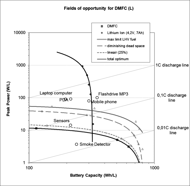
In Flipsen (2007, 2009), a simple method to find applications for DMFC power systems is described. A so-called Ragone plot is set up to screen the various fields of opportunity for the DMFC and the lithium-ion battery (Figure D.2.3).1 In Figure D.2.3, an overlay is made of different existing applications. Low-power, long-endurance applications seem to be especially interesting for DMFC systems.
Figure D.2.3 Fields of opportunity for a DMFC power system compared the lithium-ion battery (Flipsen, 2007)

D.2.3 Designing Alternative Power Sources
A third problem that designers face is the dimensions of a new power source. Component volume and size are of particular importance when giving form to an application. Batteries are a main functional component accounting for, in general, from 10% (for laptop computers) to 30% (for cell phones) of the total volume.
For primary batteries a limited number standard forms exists, making the choice easier when designing. When the lithium-ion rechargeable battery was introduced, the form was not standardized. Cell phones and other flat electronic devices directed the shape from cylindrical to a thin flat prismatic form, the cheaper pouch cell, or even the less energy-dense flexible cell. In general, however, the battery is available in prismatic form. Dimensioning a battery in the concept phase depends on three important constraints: (1) the energy it has to contain (Wh), (2) charge and discharge currents (C), and (3) the number of cycles (i.e., the cycle life of the battery).
The procedure is almost as easy as dividing the energy the application needs by the energy density of the specific battery (Wh L−1). The knowledge to make the choice can be derived from an expert, a handbook, or specification sheets from battery manufacturers. This procedure is well implemented in the CES-based power source selection tool described in Section D.2.1.
However, to overcome some of the limitations of electrochemistry, size, and shape, often two or more power supplies are used within the same system. Typically a hybrid power supply combines a high-power dense element for high-power pulses, and a high-energy-dense element for low sustaining power. Different studies have shown that improved performance is possible with hybrid supplies (Drews et al., 1999; Wu et al., 2000).
Giving form to multicomponent power sources like FC hybrids and other hybrid power sources is not as easy as giving form to stand-alone batteries. When minimizing size, mass, or costs in hybrid power source design, one specific optimization tool is of interest: Power Optimization for Wireless Energy Requirement (POWER), developed at the University of Michigan's Wireless Integrated Microsystems Engineering Research Center (WIMS-ERC) (Albano et al., 2007; Cook and Sastry, 2005; Cook et al., 2006). Factors influencing selection of the power supply can be summarized as follows (Cook and Sastry, 2005):
- Electrochemistry: cell potential, discharge–charge profile, capacity, and lifetime.
- Geometry: surface area, volume, and mass.
- Environment: temperature, pressure, and exposure.
Cook and colleagues (Cook and Sastry, 2005; Cook et al., 2006) describe a systematic method for the selection and design of a power system for a WIMS Environmental Monitor Testbed (EMT). The method focuses on selecting and designing power supplies for microelectronic devices that are prescribed after the design is nearly complete. The methodology constraints are operating temperature, energy and power density, and specific energy and power. Further requirements and constraints on rechargeability, mass, volume, and lifetime are allowed in selecting the appropriate battery electrochemistries or configurations like parallel, series, and combinations thereof. The algorithm (implemented in MATLAB code) separately evaluates the results of three strategies (approaches) to system design, specifying:
The methodology focuses on micro-power systems combining single primary and secondary batteries, often applied in implantable electronics where volume and weight of the power source are of great importance.
D.2.4 Optimizing Tools
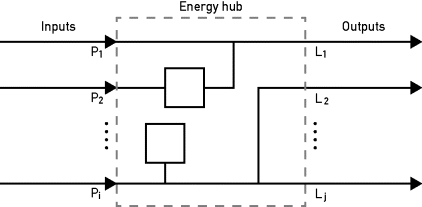
In del Real et al. (2008) hybrid power systems, combining larger power systems with energy storage systems, are optimized for element sizing. The optimizing is based on costs, not on size. So-called energy hubs are introduced, an optimal hub layout of a power system described as in Figure D.2.4. Converters link inputs and outputs through coupling factors that can be considered to be the converter's steady-state energy efficiency. In general, a “system approach” is applied, and the costs of the system are optimized based on normalized investment cost per hub element (e.g., a wind generator costs approximately $2 per W) and normalized input data (e.g., from available wind power). Other optimization tools use dynamic models to optimize hybrid electric energy generators with two main objectives in mind: the efficiency of the system and the unmet load. These optimization tools are focused on the total net present cost (NPC) throughout the lifespan for both off-grid and grid-connected power systems for remote, stand-alone, and distributed generation (DG) applications. Enumerative methods like HOMER (Lilienthal and Lambert, 2009) evaluate all possible solutions requiring excessively high calculation time. To reduce time heuristic techniques, (like) genetic and evolutionary algorithms are applied; an example is the hybrid optimization by genetic algorithm (HOGA) (Bernal-Agustin and Dufo-Lopez, 2009a, 2009b).
Figure D.2.4 General energy hub diagram (del Real et al., 2008)

D.2.5 Discussion
A few methods and tools have been found that could support the industrial designer in making a choice for a power source in different phases of design. The method described by Cook and colleagues (Cook and Sastry, 2005; Cook et al., 2006) is generally used in the end phase of design, when all constraints (application characteristics) are defined and a power source is chosen “off the shelf.” This is common practice, but choosing the power source would ideally take place at the beginning of the concept phase.
The comparison methods described by Fu et al. (2005) and Flipsen (2006) are very useful at the start of the concept phase, when only the constraints and requirements are known. The methods indicate the possibilities and opportunities of new power sources and energy storage devices. After “screening” power sources, the next step should be sizing the chosen power system. In the method of Fu et al., the mass and volume parameters are simplified. For instance, the mass of the FC is considered as equivalent to the mass of the fuel, which in general provides a good estimate but may result in problems in the outer application field. As described in Flipsen (2007), the strength of DMFCs seems to be in their low-power, long-endurance applications, where the fuel mass probably exceeds the mass of the FC system.
The tools described in Lilienthal and Lambert (2009) and in Bernal-Agustin and Dufo-Lopez (2009a, 2009b) can do both in one step. The methods described are used in larger scale power systems like wind power in combination with alternative storage systems. All combinations of power sources and energy storage systems are evaluated, and the optimal (i.e., least cost) combination is chosen. This method is quite enumerative and thus time-consuming.
