
Application of Nanofluid in Heat Exchangers for Energy Savings
M. Monjurul Ehsan, Shafi Noor, Sayedus Salehin and A.K.M. Sadrul Islam, Department of Mechanical & Chemical Engineering, Islamic University of Technology, Board Bazar, Gazipur, Dhaka, Bangladesh
Nanotechnology is a promising field in sustainable energy to reduce the energy consumption for optimum design of heat exchangers. Nanofluid provides significant improvement of thermo-physical properties and augmentation of heat transfer coefficients as well as reduces the pumping power if properly selected. In this chapter a CFD simulation using a finite volume method is presented for investigation of the hydrodynamic and thermal behavior of nanofluid flowing through a circular tube of heat exchanger with constant heat flux under single-phase turbulent flow condition for Reynolds number from 4000 to 20,000. Three different nanoparticles (Al2O3, CuO, and TiO2) with different volume fractions (1–5%) dispersed in water are analyzed. The heat transfer coefficient and pumping power increase with the increase in both the Reynolds number and volume fraction. The maximum saving of pumping power at a particular heat transfer coefficient has been obtained at 2% volume fraction for Al2O3–water and TiO2–water nanofluid and at 3% volume fraction for CuO–water nanofluid.
Keywords
Heat exchanger; CFD; nanofluid; volume fraction; heat transfer coefficient; pumping power
4.1 Introduction
In sustainable energy, nanotechnology is a prominent mechanism for intensifying the heat transfer performance of working fluid by a stable homogeneous dispersion of solid nanoparticles in traditional base fluids, such as water, oil, ethylene glycol, etc. By the addition of nanoparticles the thermo-physical properties of the working fluid are significantly improved, including thermal conductivity, viscosity, convective heat transfer coefficient, electrical conductivity, Seebeck coefficient, and optical scattering coefficients. The thermal performance, as well as the hydrodynamic characteristics, depend on the type of nanoparticle and its size, shape, and volume concentration. Nanofluid is one of the innovative and inexpensive ways which provide a strong motivation in developing more compact heat exchangers for industrial applications.
Nanofluids have the potential for numerous implementations in all aspects of heat transfer. Such practical implementations include cooling and heating of equipment, refrigerators, heating ventilation and air conditioning (HVAC) systems, automobile radiators, electronic devices, squares and cavities, solar systems, nuclear systems, biomedical applications, engine cooling and transmission oils, high-power lasers, lubrications, heating and cooling of buildings, transformer cooling oils, boiler exhaust flue gas recovery, medical applications, space defense and ships, antibacterial activities, grinding, fuel cells, thermal absorption systems, etc. [1].
4.2 Types of Nanoparticles and Nanofluid Preparation
Nanoparticles can be classified as solid metals, metal oxides, and magnetic and ferromagnetic nanoparticles. Some of the examples of solid nanoparticles are copper, silver, nickel, gold, and metal oxides, and magnetic and ferromagnetic types are Al2O3, TiO2, ZnO, SiO2, Fe2O3, MgO, etc. Various forms of carbon, such as diamond, graphite, and carbon nanotubes, are also commercially implemented as nanoparticles [2]. These nanoparticles are uniformly dispersed to a conventional base fluid such as water, engine oil, ethylene glycol, ethanol, car engine coolant, terpineol, diesel oil and polydimethylsiloxane, propylene glycol, ethanol–isopropanol, or any other mixture of two liquids.
The mechanism of preparing nanofluid is the homogeneous, stable, and uniform suspension of nanoparticles in base fluid at desired volume fraction. Nanofluid can be synthesized by two techniques: the one-step method and the two-step method [3]. In the one-step method, the synthesis of nanoparticles to preferred volume concentration and preparation of nanoparticles is performed by a combined process with minimized agglomeration. Physical vapor deposition and liquid chemical method are commonly used in the one-step method for low-pressure fluids. In the two-step method nanoparticles are synthesized to the preferred size and shape and then dispersed uniformly into the base fluid at a particular volume fraction. Surfactant and/or additives are used for better stability, minimum sedimentation and for controlling pH to a desired level. The synthesis process of nanoparticles in the two-step method can be performed by grinding, milling, sol–gel, wet chemical methods, laser ablative technology, hydrothermal technique, gas phase synthesis, and so on. Of course, the choice of methods depends upon the types, shapes of nanoparticles, and their applicability. Table 4.1 demonstrated the different types of nanoparticles with synthesis process [4].
Table 4.1
Synthesis methods of nanofluids [4]
| Types of nanoparticles | Substances | Synthesis methods |
| Amorphous nanoparticles | Fe2O3, Fe3O4, Ni, Ag | Sonochemical synthesis |
| SnO2 | Gas phase condensation | |
| Al2O3, Co | Laser ablation condensation | |
| TiO2 | Sol–gel method | |
| Ni–W–P | Electroless deposition | |
| Fe2O3, GeO2 | Hydrolysis followed by condensation | |
| Fe2O3, Ni–B | Thermally induced solid-state decomposition | |
| Magnetic nanoparticles | Fe3O4, γ-Fe2O3 | Co-precipitation |
| Fe–Co, Fe(CO)5 | Thermal decomposition | |
| Metallic cobalt, cobalt/platinum alloys, gold-coated cobalt/platinum | Microemulsion | |
| Fe47Co53 | Inert gas condensation process | |
| Ferroelectric nanoparticles | Titanium and zirconium alkoxides | Sol–gel method |
| Ba2TiO5CO3 and other barium titanate (BTO) nanoparticles | Thermal decomposition technique | |
| Lead zirconatetitanate nanoparticles | Laser ablative technology | |
| BTO ultrafine particles | Alkoxide method | |
| Barium strontium titanate nanoparticles | Wet chemical synthesis | |
| Ferroelectric La-substituted nanoparticles | Pulsed-laser deposition |
4.3 Application of Nanofluid in Heat Exchangers
Heat transfer equipment is extensively used in all aspects of engineering applications, such as HVAC systems, refrigeration systems, automobile radiators, electronic devices, process industries, etc. Numerous scientific researches have been carried out in the past few decades to discover a suitable heat transfer fluid to design more compact heat exchangers with excellent thermal efficiency. Nanotechnology offers a novel approach in intensifying the heat transfer characteristics by utilizing the higher thermal conductivity of solid nanoparticles. In recent years heat transfer augmentation achieved immense momentum due to the increased demand for energy consumption optimization in a great deal of industrial and engineering equipment, such as compact heat exchangers.
Behzadmehr et al. [5] worked with Cu–water nanofluid to investigate the turbulent convective heat transfer characteristics in a circular tube by a single-phase model and results were compared with a mixture model. A significant enhancement of average Nusselt number was observed with Reynolds number increment. Santra et al. [6] studied numerically the heat transfer with Cu–water nanofluid under laminar flow conditions through two isothermally heated parallel plates considering nanofluid as a cooling medium. The heat transfer rate was enhanced with an increase of Reynolds number and particle volume concentration. Heidary and Kermani [7] presented a numerical work to investigate the effect of Reynolds number, particle volume fraction, and wave amplitude on Nusselt number and skin friction coefficient in sinusoidal-wall channel for constant wall temperature. Cu–water was used as the nanofluid and a maximum 50% enhancement of heat transfer was found as compared to water. Ahmed et al. [8] reported a considerable enhancement of heat transfer by employing nanofluid through an isothermally heated triangular-shaped corrugated channel for a range of Reynolds number 100–1000 and nanoparticle volume fraction up to 5%. Vatani and Mohammed [9] studied turbulent convective heat transfer to observe the thermal and hydraulic performance in rectangular, triangular, and arc-shaped rib-grooved channels and a comparison was made between Al2O3, SiO2, CuO, ZnO nanoparticles using water as the base fluid. SiO2–water nanofluid provided the highest average Nusselt number while rectangular-shaped rib-grooved channel showed better performance in terms of performance evaluation criterion.
Talebi et al. [10] provided a numerical study of mixed convection flows in a square lid-driven cavity for a range of Rayleigh number 104–106, Reynolds number 1–100, and volume fraction up to 0.05%. The results revealed that at relatively higher Rayleigh number, the volume fraction of nanoparticles had a profound effect on the flow pattern and thermal performance. Abu-Nada et al. [11] showed the natural convection heat transfer intensification in horizontal concentric annuli using four different types of water base nanofluids. Among Cu, Ag, Al2O3, and TiO2 nanoparticles, Al2O3 gave the highest heat transfer rate at higher values of Rayleigh number. Akbarinia and Behzadmehr [12] studied the influence of buoyancy force, centrifugal force, and concentration of Al2O3 nanoparticles on convection heat transfer in horizontal curved tubes. For a given volume fraction of nanoparticles, buoyancy force caused a reduction in skin friction and at low Grashof number volume fraction had no visible effect on the skin friction. To improve the cooling system performance in automobile car radiators, Hussein et al. [13] performed a numerical simulation to investigate the effect of cross-sectional area of tube on friction factor and heat transfer by employing TiO2–water nanofluid as coolants in radiators. Circular, elliptical, and flat tubes were the geometry consideration and the flat tube showed the highest average heat transfer coefficient. Peyghambarzadeh et al. [14] employed Al2O3–water nanofluid as coolants with a range of volume concentration 0.1–1% in automobile radiators and up to 45% enhancement of heat transfer was obtained in comparison to base fluid. Ijam and Saidur [15] analyzed with SiC–water and TiO2–water nanofluids as coolants in mini-channel heat sink for the improvement of cooling performance in electronic devices. For a given volume concentration, SiC–water nanofluid gave a greater heat transfer rate compared to TiO2–water nanofluid.
Clancy [16] experimented with nanofluid in the condenser of a vapor compression system for heat transfer enhancement and energy savings. Firouzfar et al. [17] experimentally investigated the efficacy of a heat pipe heat exchanger in air conditioning systems by the suspension of silver nanoparticles in pure methanol. The sensible effectiveness was 5–22% for pure methanol whereas it was 9–32% for methanol–silver nanofluid. Maghrebi et al. [18] investigated forced convection heat transfer of nanofluids in a porous channel and the effects of Lewis number, Schmidt number, and Brownian diffusion on heat transfer performance. Harikrishnan and Kalaiselvam [19] conducted an experiment on solidification and melting characteristics of TiO2–melting palmitic acid nanofluid as Phase Change Material (PCM) for solar water heating systems. Enhancement of heat transfer was caused by the addition of nanoparticles in palmitic acid with different volume concentration.
Duangthongsuk and Wongwises [20] performed an experiment on heat transfer enhancement and pressure drop characteristics of TiO2–water nanofluid in a double-tube counter-flow heat exchanger and investigated the friction factor and heat transfer characteristics under turbulent flow with a range of Reynolds number 4000–18,000. They observed an increment of convective heat transfer coefficient with an increase of Reynolds number and mass flow rate of heating fluid in the heat exchanger. γ-Al2O3–water and TiO2–water nanofluids were used experimentally in a horizontal stainless steel shell and tube heat exchanger under turbulent flow conditions to study the effect of Peclet number, volume concentration of suspended nanoparticles, and particle type on the forced convection heat transfer characteristics [21]. Significant improvement of heat transfer was observed with the addition of nanoparticles to the base fluid at the same Peclet number and also the optimum volume concentration for both nanofluids was determined. Fard et al. [22] carried out a numerical and experimental investigation of heat transfer of ZnO–water nanofluid as hot stream in the concentric tube and plate heat exchanger and overall heat transfer coefficients in both heat exchangers were calculated as a function of hot and cold streams mass flow rates. The enhancement of heat transfer was 20% for the plate heat exchanger and 14% for the concentric heat exchanger. Leong et al. [23] proposed a numerical model of shell and tube heat recovery exchanger operated with nanofluid-based coolants and achieved 7.8% of the heat transfer enhancement with the addition of 1% copper nanoparticles in ethylene-glycol-based fluid at a mass flow rate of 26.3 and 116.0 kg s−1 for flue gas and coolant respectively under laminar flow conditions. Gunnasegaran et al. [24] described a numerical model with three different types of nanofluids in ethylene glycol base fluid, namely copper, diamond, and silicon dioxide on an automobile flat tube plate-fin cross-flow compact heat exchanger considering 2% volume concentration and a single-phase approach. Variations of shear stress, skin friction, and convective heat transfer coefficient were studied and improvement of thermal performance was shown with an increase of air and coolant Reynolds number.
Zamzamian et al. [25] experimented on forced convective heat transfer in a double pipe and plate heat exchanger under turbulent flow conditions using Al2O3 and CuO nanoparticles dispersed in ethylene glycol. Enhancement of convective heat transfer coefficient was shown with an increase in particle volume concentration and nanofluid temperature. The heat transfer rate was increased by 2–50% compared to the base fluid and results were compared with theoretical calculations. Kannadasan et al. [26] performed an experiment with a horizontal and vertical helically coiled heat exchanger to compare the pressure drop and heat transfer characteristics with Cu–water nanofluid under turbulent flow conditions. Heat transfer enhancement was found more in the vertical heat exchanger and friction factor increased with particle volume concentration. Pantzali et al. [27] worked with CuO–water nanofluid as coolant with 4% volume fraction to discover the effectiveness of plate heat exchanger and established that heat transfer augmentation was accomplished by addition of nanoparticles and viscosity of nanofluid worked as an essential factor on thermal performance of heat exchanger. Pandey and Nema [28] applied a sine-shaped corrugated channel in a plate heat exchanger where Al2O3–water nanofluid was considered as a coolant, to investigate the heat transfer, frictional loss and pumping power with nanofluid volume concentration. The experimental results confirmed that for a given heat load, the volumetric flow rate of nanofluid decreased with significant pressure drop and improvement of heat transfer rate was maximum at 2% volume concentration of Al2O3 nanoparticles at a Peclet number of 7700. Elias et al. [29] provided an analytical solution to observe the effect of different nanoparticle shapes on the enhancement of heat transfer and the thermodynamic performance of a shell and tube heat exchanger. Al2O3 nanoparticles of different shapes were dispersed in a water–ethylene glycol mixture. Cylindrical-shaped nanoparticles were found to be the optimum particle shape in the heat exchanger for better heat transfer performance. Sonawane et al. [30] conducted an experiment with Al2O3–water nanofluid on a concentric heat exchanger to study the average heat transfer rate. The convective heat transfer coefficient was improved with an increase of Reynolds number and particle volume concentration. Besides, many researchers [11,31–33] carried out studies on heat transfer enhancement with nanofluids in different types of heat exchangers to enhance the overall thermal performance, both numerically and experimentally.
In the literature most of the studies focused on the enhancement of heat transfer utilizing nanofluid in different engineering applications. Very little information is available in the literature that deals with the pumping power issue of the nanofluid. Considering this fact, the scope of this chapter is to investigate the heat transfer characteristics and pumping power requirements of different water-based nanofluids (Al2O3, CuO, and TiO2) with different volume fractions through a circular pipe of a typical heat exchanger. By the dispersion of nanoparticles in base fluid, the heat transfer rate is intensified but with the cost of pumping power. In the present numerical work, an optimum volume fraction for different nanofluids for a certain range of Reynolds number is obtained for which the nanofluid provides less pumping power compared to water. At a volume fraction, lower or higher than this optimum one, there is no or little advantage in reduction of pumping power as well as the mass flow rate of nanofluid. Finally, for the same heat transfer coefficient, reduction of pumping power, mass flow rate, and volumetric flow rate of all three nanofluids are examined within a preferred particle volume fraction.
4.4 Physical Model and Boundary Values
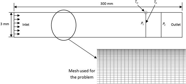
A pipe with a constant heat flux applied on its surface can be considered as the simplest case of a heat exchanger to investigate the heat transfer rate and corresponding pumping power requirements. In order to investigate the performance of nanofluid in a circular tube, a numerical study has been carried out by employing commercial computational fluid dynamics software ANSYS Fluent. A turbulent flow through a circular tube of 3 mm diameter and 300 mm length is presented. A constant uniform heat flux of 5000 W m−2 is applied at the wall boundary of the circular tube and fluid is allowed to flow with a plug velocity and uniform temperature of 300 K at the inlet of the tube with an assumption of no slip condition on the tube wall. All the fluid dynamic and heat transfer parameters are extracted after the hydrodynamic and thermal development of the fluid flow and in this case the entrance length is x/D=60 beyond which all the measurements are taken.
A two-dimensional flow of uniform velocity is considered at the inlet and numerical simulation is carried out by considering an axisymmetric flow, which is shown in Figure 4.1. The wall temperature and bulk temperature are taken at a distance of 275 mm from the inlet. The pressure difference is measured by taking the pressure at two sections at distances of 275 and 290 mm from the inlet respectively.
4.5 Governing Equations
The governing equations for continuity, momentum, and energy for forced convection under turbulent flow and steady-state conditions are expressed as follows:
Continuity equation:
[4.1]
Momentum equation:
[4.2]
Energy equation:
[4.3]
Here ![]() is molecular thermal diffusivity and
is molecular thermal diffusivity and ![]() is turbulent thermal diffusivity which can be expressed as:
is turbulent thermal diffusivity which can be expressed as:
The normal Reynolds stress which is combined by Boussinesq relationship and the eddy viscosity definition is given by:
[4.4]
The realizable k−ε model is considered to model turbulent eddy viscosity and transport equation for turbulent kinetic energy and turbulent dissipation rate which has been derived from an exact equation for the transport of the mean-square vorticity fluctuation [34].
Turbulent eddy viscosity is defined as:
Turbulent kinetic energy:
[4.5]
Turbulent dissipation rate:
[4.6]
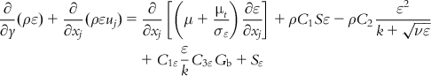 [4.6]
[4.6]
where
Here Gk represents the generation of turbulent kinetic energy due to the mean velocity gradients, Gb is the generation of turbulent kinetic energy due to buoyancy, YM represents the contribution of the fluctuating dilatation in compressible turbulence to the overall dissipation rate, and σk and σε are the turbulent Prandtl for k and ε respectively.
4.6 Thermal and Fluid Dynamic Analysis
The Reynolds number for the flow of nanofluid is expressed as:
The rate of heat transfer Qnf to the tube wall is assumed to be totally dissipated to nanofluid flowing through a circular tube, raising its temperature from inlet fluid bulk temperature Tbi to exit fluid bulk temperature Tbo. Thus,
[4.7]
where ![]() is the mass flow rate of nanofluid,
is the mass flow rate of nanofluid, ![]() is the specific heat of nanofluid at constant pressure. The definition of bulk temperature Tb is given by:
is the specific heat of nanofluid at constant pressure. The definition of bulk temperature Tb is given by:
[4.8]
 [4.8]
[4.8]Ac is cross-sectional area of the circular section. The average heat transfer coefficient, hc is given by:
where AW is the surface area of circular tube and the temperature difference between the wall and the fluid is calculated as:
[4.9]
So the expression of average Nusselt number is defined as follows:
[4.10]
The pumping power per unit length in turbulent flow is given by:
[4.11]
where ΔP is differential pressure difference
[4.12]
4.7 Thermophysical Properties of Nanofluid
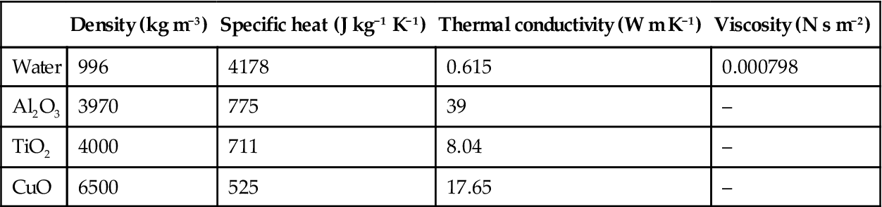
In this study Al2O3, CuO, and TiO2 nanoparticles of diameter of 50 nm are considered to be dispersed in water as the base fluid. The properties of the base fluid and the nanoparticles are given in Table 4.2.
Table 4.2
Thermophysical properties of water and nanoparticles
| Density (kg m−3) | Specific heat (J kg−1 K−1) | Thermal conductivity (W m K−1) | Viscosity (N s m−2) | |
| Water | 996 | 4178 | 0.615 | 0.000798 |
| Al2O3 | 3970 | 775 | 39 | – |
| TiO2 | 4000 | 711 | 8.04 | – |
| CuO | 6500 | 525 | 17.65 | – |
The effective thermophysical properties of different nanofluids have been calculated using different empirical equations which are given as follows.
4.7.1 Thermal Conductivity
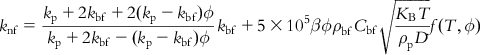
Koo and Kleinstreuer [35] developed a correlation to calculate the effective thermal conductivity of nanofluid considering the effect of the diameter of the solid nanoparticles, volume fraction, and temperature of the nanofluid, properties of the basefluid and nanoparticles and the Brownian motion of the solid particles within the base fluid.
[4.13]
 [4.13]
where f(T,ϕ)=(−6.04ϕ+0.4705)T+(1722.3ϕ−134.63)
4.7.2 Dynamic Viscosity
The dynamic viscosity of nanofluid is given by the following empirical correlation developed by Corcione [36] with 1.84% of standard deviation.
[4.14]
where dbf is the equivalent diameter of the base fluid molecule, and is given by:
where M is the molecular weight of the base fluid, N is the Avogadro number, and ρfo is the mass density of the base fluid calculated at temperature To=293 K.
4.7.3 Density
The density of nanofluids is calculated from the following correlation [37]
[4.15]
4.7.4 Specific Heat
The specific heat of nanofluids is formulated by the following equation [37]
[4.16]
The graphs in Figure 4.2 show the variation of thermophysical properties with the volume fraction for different nanofluids. The volume fraction 0% corresponds to water.

The density of the nanofluids increases with the increase in volume fraction and CuO–water shows the highest density compared to the other two nanofluids [Figure 4.2(a)]. The specific heat of the nanofluids decreases with the increase in the volume fraction [Figure 4.2(b)] where CuO–water shows lower values than the other nanofluids. The thermal conductivity increases with the volume fraction and CuO–water nanofluid gives lower values [Figure 4.2(c)]. Although this thermal conductivity has an increasing trend with the change in volume fraction, at volume fractions beyond 4% the thermal conductivity of all three nanofluids shows a decreasing trend. Since the viscosity depends on the size of the nanoparticles only and we have considered all the nanoparticles of diameter 50 nm, all three nanofluids give the same values of the viscosity [Figure 4.2(d)]. For all these thermophysical properties, Al2O3–water and TiO2–water nanofluids give similar property values.
4.8 Numerical Method
A commercial computational fluid dynamics software ANSYS Fluent has been used for this numerical analysis. The governing equations for mass, momentum, energy, and turbulent quantities are solved using a control volume technique. Realizable k−ε turbulent model is chosen with enhanced wall treatment for the single-phase analysis. At inlet turbulent intensity is taken as 5% and at the outlet boundary pressure outlet is considered. A SIMPLE algorithm for the velocity–pressure coupling is adopted and under discretization scheme, second-order upwind method for energy, momentum, turbulent kinetic energy, and turbulent dissipation rate equation is prescribed. Under relaxation factors 0.3 for pressure, 0.4 for momentum, 0.8 for turbulent kinetic energy, 0.8 for turbulent dissipation rate, 0.95 for energy equation, and 1 for turbulent viscosity are considered. The convergence criterion for all the parameters was set on the order of 10−7.
Heat transfer parameters like convective heat transfer coefficient and average Nusselt number and fluid dynamic parameters like pressure drop, friction factor and pumping power are calculated. CuO–water, TiO2–water, and Al2O3–water nanofluids with different particle volume fractions (1, 1.5, 2, 3, 4, 5%) are tested with a wide range of Reynolds number (4000–20,000) and results are compared with base fluid. With an increase of Reynolds number and particle volume fraction, heat transfer characteristics and fluid flow behavior are investigated. By the addition of nanoparticles with a low-volume concentration in base fluid, the enhancement of heat transfer, the increase of frictional losses, and the pumping power in comparison with water are studied under the prescribed flow condition.
4.9 Code Validation
A flow of water with uniform velocity and a range of Reynolds number of 4000–20,000 has been considered and the calculated Nusselt numbers at the fully developed zone are validated with the values of Nusselt number obtained from Notter and Sleicher correlation [38] which is shown in Figure 4.3.

The correlation developed by Notter and Sleicher is as follows:
[4.17]
where
![]()
It has been found that the results obtained using the present code are in good agreement with the Notter and Sleicher correlation.
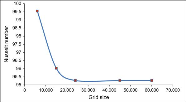
4.10 Grid Independence Test
For the grid independence study, working substance has been taken as water and the simulation was run at Re=12,000. Grid independence test was carried out to discover the optimum grid size for the present study. Five different grid sizes (300×20, 500×30, 600×40, 900×50, and 1000×60) were tested to find out the effect on the Nusselt number calculated at a distance of 275 mm from the inlet of the tube. It has been found that there is no significant change in Nusselt number beyond the grid size of 600×40 (24,000), which is shown in Figure 4.4. Therefore, for the present study, the grid size of 24,000 has been used to perform all the simulations.
4.11 Results and Discussions
4.11.1 Heat Transfer Coefficient for Different Volume Fraction of Nanofluid
Figure 4.5 shows the effect of volume fraction on the heat transfer coefficient for Al2O3–water nanofluid. It has been found that the heat transfer coefficient increases with the increase in Reynolds number and volume fraction of nanofluid. A similar trend has been obtained for the other two nanofluids: CuO–water and TiO2–water. A similar trend has also been reported by Vajjha and Das [39] for Al2O3 in an EG–water mixture.

4.11.2 Heat Transfer Coefficient for Different Nanofluids at the Same Volume Fraction
Figure 4.6 shows the effect of different types of nanofluids at a volume fraction of 2%. Al2O3–water and TiO2–water nanofluids show similar enhancement in heat transfer coefficient with the increase in Reynolds number. CuO–water nanofluid shows lower improvement of heat transfer coefficient compared to the other two nanofluids.

From Figures 4.5 and 4.6, it is obvious that there is a significant enhancement in the heat transfer rate of a flow through tube. However, this enhancement can not be justified if the pumping power required for nanofluid is more than that of water, which demands further investigation of the pumping power for the same requirement of heat transfer rate.
4.11.3 Pumping Power
From Figure 4.7, it is observed that the required pumping power for both water and nanofluid increases with the increase in Reynolds number. Nanofluid requires more pumping power compared to water and this value increases with the increase in the volume fraction and Reynolds number. At flows having a lower Reynolds number, the difference among the values of pumping power per unit length for different volume fraction is comparatively smaller.

Figure 4.8 shows the change in pumping power per unit length with the Reynolds number for water and all three nanofluids at a volume fraction of 2%. The requirement for the pumping power is higher for the nanofluids than that of water. However, Al2O3–water and TiO2–water require almost similar pumping power and this is higher than CuO–water nanofluid. In this case also, this difference is more visible at a higher Reynolds number.

From Figure 4.9(a), it can be seen that the requirement of the pumping power increases with higher values of heat transfer coefficient. The pumping power is almost the same for the volume fraction of 1.5 and 2%. Figure 4.9(b) shows a zoomed part of the graph from h=10,000 to 15,000 W m−2 K−1. The Al2O3–water nanofluid of all volume fraction requires less pumping power than water for a constant heat transfer rate of less than 11,000 W m−2 K−1 beyond which 5% always requires more pumping power. The volume fraction 1–3% always requires less pumping power than water for the same heat transfer rate. For a volume fraction of 4%, the pumping power requirement is higher than water at a range of h=11,600 to 14,600 W m−2 K−1. Figure 4.9(c) shows a zoomed portion of the graph to illustrate the trend to which the nanofluid of different volume fraction behaves in terms of pumping power for the same heat transfer rate. For the range h=28,000 to 30,000 W m−2 K−1, from ϕ=1% to 2%, the enhancement in the pumping power gradually increases and, beyond 2% volume fraction, the required pumping power becomes higher. At a volume fraction of 5%, the required pumping power is higher than water. In a similar way, the values of pumping power requirement for h=20,000 W m−2 K−1 have been found and illustrated in Figure 4.10.


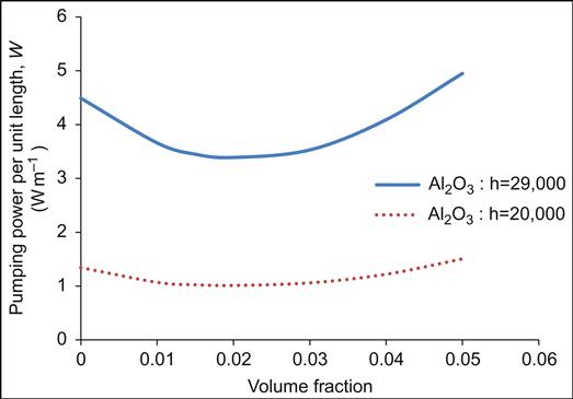
From Figure 4.10, it is seen that the minimum pumping power occurs at a volume fraction of 2% for both h=20,000 and 29,000 W m−2 K−1. In their analytical study on the pumping power requirement using ethylene-glycol-based nanofluid, Vajja and Das [39] found a maximum enhancement at a volume fraction of 1% for CuO–E/G, Al2O3–E/G, and SiO2–E/G nanofluid. The above phenomenon can be well illustrated by the concept of the Mouromtseff number, Mo. The Mouromtseff number is a figure of merit for comparing the relative heat transfer coefficient [39]. For a fully developed turbulent flow, the Mouromtseff number is given by [40]:
[4.18]
and
[4.19]
For the thermophysical properties of Al2O3–water nanofluid, the relative heat transfer rate (Monf/Mobf) has been plotted against the volume fraction which is shown in Figure 4.11.
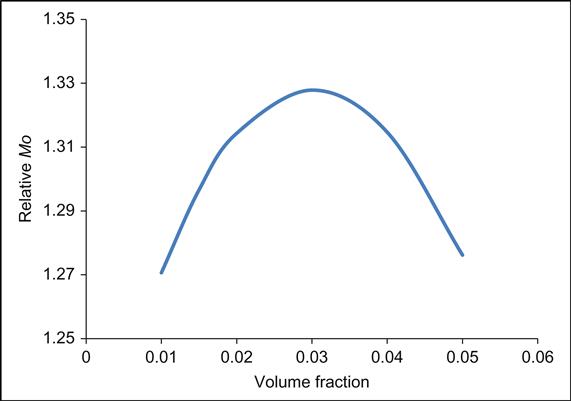
From Figure 4.11, it can be seen that the relative heat transfer rate is maximum at a volume fraction of 3%, which indicates a maximum pumping power advantage around this particular volume fraction. TiO2–water nanofluid shows similar behavior as that of Al2O3–water nanofluid. In the case of CuO–water nanofluid, the pumping power requirement is less than the other two nanofluids for which, at a volume fraction of 5%, it is almost the same as that of water.
4.12 Case Study for a Typical Heat Exchanger
Hot superheated steam flowing over the tubes containing nanofluid inside a heat exchanger may be considered to study the effect of nanofluid in reducing the total heat transfer surface area, thereby decreasing the total cost for tube material and requiring less space for the heat exchanger. The heat flux applied due to the hot superheated steam is assumed to be Q=5000 W m−2 on the wall of the tube. Using the equations from Ozisik [41]:
[4.20]
where Uo is the overall heat transfer coefficient, Ao is the outer surface area of the tube, and Δtm is the difference between the mean temperature of the fluid flowing inside the tube and the ambient temperature of the superheated steam flowing over the tube.
The thermal resistance of the system is:
[4.21]
 [4.21]
then
[4.22]
[4.23]
From Eq. (4.20), the heat transfer surface area has been found and the percentage reduction in the heat transfer surface area is calculated by using nanofluid as the working substance which is illustrated in Table 4.3.
Table 4.3
Comparison of reduction in the heat transfer surface area for nanofluids and water
| Component | Water | 2% Al2O3 | 2% TiO2 | 2% CuO |
| Reynolds number | 8000 | 8000 | 8000 | 8000 |
| Inside heat transfer coefficient, hi (W m−2 K−1) | 14,005.602 | 17,064.846 | 17,006.803 | 16,556.291 |
| Inside surface resistance, Ri | 0.0075727 | 0.0062152 | 0.0062364 | 0.0064061 |
| Pipe wall resistance, Rp | 0.0002027 | 0.0002027 | 0.0002027 | 0.0002027 |
| Outside surface resistance, Ro | 0.0318182 | 0.0318182 | 0.0318182 | 0.0318182 |
| Total resistance, Rt=Ri+Rp+Ro | 0.0395936 | 0.038236 | 0.0382572 | 0.0384269 |
| Overall heat transfer coefficient, Uo | 1607.2398 | 1664.3051 | 1663.3823 | 1656.0367 |
| Heat transfer area | 0.0207 | 0.02003 | 0.02004 | 0.02013 |
| % reduction in heat transfer area | – | 3.43 | 3.38 | 2.95 |

Table 4.3 shows an increase in the overall heat transfer coefficient when nanofluid is used instead of water. Considering constant heat flux of 5000 W m−2 and a constant temperature of steam as 450 K, the heat transfer surface area is calculated. Thus percentage reductions of 3.43%, 3.38%, and 2.95% in the heat transfer area have been obtained for Al2O3–water, TiO2–water, and CuO–water nanofluids, having a volume fraction of 2%, respectively. In a similar study carried out by Kulkarni et al. [42] considering ethylene–glycol–water-based nanofluid, 8.5% reduction in the surface area for 6% silicon dioxide, 17.3% reduction for 6% aluminum oxide and 20.37% reduction for 6% copper oxide have been achieved.
The performance of various nanofluids with the base fluid water is illustrated in Table 4.4. Here it is observed that a considerable improvement in the pumping power and reduction in the mass flow rate has been obtained by using nanofluid.
Table 4.4
Comparison of the performance of the nanofluid with base fluid water
| Type of fluid parameter | Water | 2% Al2O3 | 2% TiO2 | 2% CuO |
| Heat transfer coefficient (W m−2 K−1) | 20,000 | 20,000 | 20,000 | 20,000 |
| Reynolds number | 12,350 | 9740 | 9760 | 10,096 |
| Pressure loss per unit length (kPa m−1) | 57.667 | 49.813 | 49.960 | 49.740 |
| Viscosity (kg m−1 s−1) | 0.000798 | 0.00093234 | 0.00093234 | 0.00093234 |
| Density (kg m−3) | 996 | 1055.48 | 1056.08 | 1271.2 |
| Specific heat (J kg−1 K−1) | 4178 | 4109.94 | 4108.66 | 4104.94 |
| Velocity (m s−1) | 3.30 | 2.868 | 2.872 | 2.468 |
| Volumetric flow rate (m3 s−1) | 0.000023326 | 0.000020271 | 0.0000203 | 0.00001744 |
| Reduction in volumetric flow rate (%) | – | 13.1 | 12.97 | 25.234 |
| Pumping power per unit length (W m−1) | 1.345 | 1.01 | 1.014 | 0.8676 |
| Power advantage (W m−1) | – | 0.335 | 0.331 | 0.4774 |
| Power advantage (%) | – | 24.9 | 24.61 | 35.5 |
| Mass flow rate (kg s−1) | 0.0232 | 0.021396 | 0.02144 | 0.02217 |
| Reduction in mass flow rate (%) | – | 7.776 | 7.586 | 4.44 |

For all three nanofluids at a constant heat transfer coefficient of 20,000 W m−2 K−1 for the optimum 2% volume fraction, the pumping power advantage and reduction in mass flow rate have been analyzed. The pumping power advantage per unit length of 24.9, 24.61, and 35.5% for Al2O3–water, TiO2–water, and CuO–water, respectively, have been achieved. It is worth mentioning that although compared to two other nanofluids, CuO shows less reduction of the heat transfer area, the advantage of the pumping power is the highest. The reduction in the mass flow rate for Al2O3–water nanofluid is 7.776%, for TiO2–water, it is 7.586% and for CuO–water, this reduction is 4.44% compared to the mass flow rate of water.
4.13 Conclusions
Three different nanofluids, namely Al2O3–water, TiO2–water, and CuO–water, have been analyzed through a typical heat exchanger tube to investigate the heat transfer enhancement and the pumping power advantage. The heat transfer coefficient increases with the increase in volume fraction of all three nanofluids as well as with the Reynolds number. However CuO–water nanofluid gives a lower value of heat transfer coefficient than the other two nanofluids. Pumping power required per unit length increases with the increase in volume fraction of the nanofluid and Reynolds number. CuO–water nanofluid gives lower values than the other two. The minimum pumping power has been obtained at 2% of volume fraction for all three nanofluids at a particular heat transfer coefficient. For a typical case study of a heat exchanger it was calculated for a heat transfer coefficient of 20,000 W m−2 K−1 and at 2% volume fraction yielded around 3% of heat transfer surface area reduction and a power advantage of 25−36% for the nanofluids.
Nomenclature
Ac Cross-sectional area of circular tube
AW Surface area of circular tube
Cp Specific heat at constant pressure
hc Average heat transfer coefficient
M Molecular weight of the base fluid molecule
W Pumping power per unit length of the pipe
T0 Reference temperature, 273 K