
Natural Convection Heat Transfer in the Partitioned Attic Space
Suvash C. Saha1, Y.T. Gu1 and M.M.K. Khan2, 1School of Chemistry, Physics & Mechanical Engineering, Queensland University of Technology, Brisbane, QLD, Australia, 2School of Engineering & Technology, Higher Education Division, Central Queensland University, Rockhampton, QLD, Australia
Heat transfer and air flow through an attic space into or out of buildings is a key issue for attic-shaped houses in different seasons. One of the main objectives for designers and builders is to provide thermal comfort for dwellers. In the present energy-conscious society, it is also a requirement for houses to be energy-efficient, that is, the energy usage for heating or cooling houses must be reduced. Relevant to these objectives, research into heat transfer in attics has been conducted for more than two decades. Numerical simulation is carried out for flow behavior of natural convection in an isosceles triangular enclosure partitioned in the center by a vertical wall with an infinite conductivity. A sudden temperature difference between two zones of the enclosure has been imposed to trigger the natural convection. As a result, heat is transferred between both sides of the cavity through the conducting vertical wall with natural convection boundary layers forming on the middle partition and two inclined surfaces. The Finite Volume-based software Fluent is used for the simulations. The numerical results are obtained for different values of height–base ratio (![]() , and
, and ![]() ) with fixed values of Rayleigh number,
) with fixed values of Rayleigh number, ![]() and Prandtl number, 0.72. It is anticipated from the numerical simulations that the coupled thermal boundary layers development adjacent to the partition undergoes several distinct stages including an initial stage, a transitional stage, and a steady stage. Time-dependent features of the coupled thermal boundary layers, as well as the overall natural convection flow in the partitioned enclosure, have been discussed and compared with the nonpartitioned enclosure. It is found that heat transfer is reduced significantly in the presence of a vertical partition which is placed in the geometrical center line.
and Prandtl number, 0.72. It is anticipated from the numerical simulations that the coupled thermal boundary layers development adjacent to the partition undergoes several distinct stages including an initial stage, a transitional stage, and a steady stage. Time-dependent features of the coupled thermal boundary layers, as well as the overall natural convection flow in the partitioned enclosure, have been discussed and compared with the nonpartitioned enclosure. It is found that heat transfer is reduced significantly in the presence of a vertical partition which is placed in the geometrical center line.
Keywords
Partition; natural convection; boundary layer; triangular enclosure; Nusselt number
3.1 Introduction
Natural convection in different shapes of enclosures is available in nature, and is a topic of considerable interest for engineers. Actually, natural convection occurs everywhere in nature. The application of studying natural convection is in the thermal design of buildings, solar collector design, nuclear reactor design and many others. There are a wealth of studies related to natural convection in enclosures available in the literature [1–4]. However, most of these studies are devoted to an enclosure with no partitions within. It is evident that placing a vertical partition in the enclosure enhances or suppresses heat transfer. There are several studies available in the literature related to vertical partitions in a rectangular enclosure [5–12]. This is a very important problem mainly for two reasons; from the fundamental research point of view it is important to understand the interaction of two convective systems coupled across a partially conducting wall. The vertical conducting partition plays an important role in heat transfer between two fluid zones. It is seen from the earlier studies that the partition depresses natural convection in the cavity in comparison with that in a nonpartitioned cavity for a laminar flow regime, even though the partition is perfectly conducting [13–17].
Several researchers have studied natural convection in rectangular enclosures with multiple vertical partitions [17–20]. The effect of multiple thin partitions has been investigated both experimentally and numerically by Nishimura et al. [17]. The experiments were performed in enclosures with aspect ratios, ![]() and 10, for the range
and 10, for the range ![]() and the range of partitions
and the range of partitions ![]() . The authors concluded that the average Nusselt number is inversely proportional to
. The authors concluded that the average Nusselt number is inversely proportional to ![]() . By placing double partitions in the middle of a rectangular enclosure, Anderson and Bejan [18] found that the heat transfer rate for double partitions is 20% less than that for a single partition. Similar studies were conducted by Jones [19], with multiple partitions for the case of laminar natural convection flows in rectangular enclosures. The author revealed that the effect of dividing the enclosure into six cells reduces the heat transfer rate by a factor of six.
. By placing double partitions in the middle of a rectangular enclosure, Anderson and Bejan [18] found that the heat transfer rate for double partitions is 20% less than that for a single partition. Similar studies were conducted by Jones [19], with multiple partitions for the case of laminar natural convection flows in rectangular enclosures. The author revealed that the effect of dividing the enclosure into six cells reduces the heat transfer rate by a factor of six.
In comparison with the rectangular or square enclosures, studies on triangular enclosures previously received less attention. However, because of its various applications in many domestic and industrial systems, as well as in geophysical flows, recently much attention has been given to this geometry [21–26]. One of the important applications of studying this geometry is to investigate fluid flow and heat transfer in the attic space. In both hot and cold climates heat transfer through the attic space is seen as an important study for attic-shaped houses. It is expected that one of the main objectives to design and construction of houses should be to provide thermal comfort for occupants. Moreover, it is also a requirement for houses to be energy-efficient as sources of energy are limited globally, that is, the energy consumption for heating or air-conditioning of houses must be minimized.
Recently, Saha et al. [27] attempted for the first time to model heat transfer through coupled thermal boundary layers in a partitioned triangular cavity for a fixed Rayleigh number and aspect ratio. There are still more research needs to be done to understand the development of coupled thermal boundary layers properly. The lack of such an investigation has motivated the present study to investigate the heat transfer phenomena for partitioned triangular enclosures for various Rayleigh numbers and aspect ratios. Emphasis has been given to the transient process of natural convection resulting from a suddenly generated temperature difference between the fluids on the two sides of a conducting partition which has been placed along the geometric center line of the enclosure.
3.2 Problem Formulation
Under consideration in this study is an isosceles triangular cavity. Figure 3.1 shows a schematic of the computational domain of height ![]() and half of length
and half of length ![]() . In order to avoid the singularities at the intersection regions between the roof and the bottom, the tiny tips of approximately 5% of
. In order to avoid the singularities at the intersection regions between the roof and the bottom, the tiny tips of approximately 5% of ![]() are cut off at both sides of the geometric plane. It is expected that the slight modification of the flow domain has an insignificant impact on the calculated flow and heat transfer (see [21–24]).
are cut off at both sides of the geometric plane. It is expected that the slight modification of the flow domain has an insignificant impact on the calculated flow and heat transfer (see [21–24]).

The development of natural convection inside an attic space is governed by the following two-dimensional Navier–Stokes and energy equations with the Boussinesq approximation:
[3.1]
[3.2]
[3.3]
[3.4]
where ![]() and
and ![]() are the velocity components along x- and y-directions respectively,
are the velocity components along x- and y-directions respectively, ![]() is the time,
is the time, ![]() is the pressure,
is the pressure, ![]() and
and ![]() are kinematic viscosity, density of the fluid, coefficient of thermal expansion and thermal diffusivity, respectively,
are kinematic viscosity, density of the fluid, coefficient of thermal expansion and thermal diffusivity, respectively, ![]() is the acceleration due to gravity and
is the acceleration due to gravity and ![]() is the temperature.
is the temperature.
In this chapter the working fluid is considered as air with Prandtl number, ![]() , which is initially at quiescent; the range of aspect ratio as
, which is initially at quiescent; the range of aspect ratio as ![]() and the range of Rayleigh number as
and the range of Rayleigh number as ![]() . Two interiors of both sides of the partition together with adjacent inclined walls receive different temperatures with the left side receiving a cold (
. Two interiors of both sides of the partition together with adjacent inclined walls receive different temperatures with the left side receiving a cold (![]() ) and the right side receiving a hot temperature (
) and the right side receiving a hot temperature (![]() ) after time t=0 s. Nonslip and adiabatic vertical walls are assumed at the cutting points of bottom tips (refer to Figure 3.1). The bottom surface is also considered as adiabatic and all three surfaces and the partition are rigid and nonslip. The thickness of the partition is considered as zero with infinite conductivity and is diathermal, for which only horizontal heat transfer is considered (refer to [9,16,18]).
) after time t=0 s. Nonslip and adiabatic vertical walls are assumed at the cutting points of bottom tips (refer to Figure 3.1). The bottom surface is also considered as adiabatic and all three surfaces and the partition are rigid and nonslip. The thickness of the partition is considered as zero with infinite conductivity and is diathermal, for which only horizontal heat transfer is considered (refer to [9,16,18]).
Natural convection flows in the cavity are determined by three governing parameters: the Rayleigh number (Ra), the Prandtl number (Pr), and the aspect ratio (A). They are defined as follows:
[3.5]
3.3 Numerical Approach and Validation
Employing the SIMPLE scheme with the help of CFD software Ansys 15.0 (FLUENT) we have solved Eqs (3.1)– (3.4) along with the initial and boundary conditions. The governing equations are discretized using the finite volume method and the advection term is approximated by the QUICK scheme. The diffusion terms are discretized using central-differencing with second-order accuracy. A second-order implicit time-marching scheme has also been used for the unsteady term.
Two nonuniform grid sizes, ![]() and
and ![]() with coarser grids in the core and finer grids concentrated in the proximity of all wall and partition boundaries were constructed for grid dependence tests for A=0.5. Figure 3.2 plots time series of the temperatures at the point
with coarser grids in the core and finer grids concentrated in the proximity of all wall and partition boundaries were constructed for grid dependence tests for A=0.5. Figure 3.2 plots time series of the temperatures at the point ![]() of A=0.5, in the middle of the thermal boundary layer on the left side of the partition calculated using the two grid systems for Ra=108. Clearly, the two solutions almost overlapped. This means that either grid system is able to resolve the transient natural convection in the partitioned cavity and characterize the details of the boundary layers adjacent to the partition and other walls.
of A=0.5, in the middle of the thermal boundary layer on the left side of the partition calculated using the two grid systems for Ra=108. Clearly, the two solutions almost overlapped. This means that either grid system is able to resolve the transient natural convection in the partitioned cavity and characterize the details of the boundary layers adjacent to the partition and other walls.

 in the middle of the developed thermal boundary layer on the left side of the partition calculated using different meshes and time steps.
Two time steps of 0.05 and 0.01 s for grid sizes of ![]() and
and ![]() respectively are examined to test the time step dependency for A=0.5. Figure 3.2 shows the numerical results obtained using the above two time steps and their corresponding grid sizes for A=0.5. Evidently, the development of the flow is not sensitive to the two tested time steps, with either choice being satisfactory. Accordingly, the larger time step of 0.05 s and coarser
respectively are examined to test the time step dependency for A=0.5. Figure 3.2 shows the numerical results obtained using the above two time steps and their corresponding grid sizes for A=0.5. Evidently, the development of the flow is not sensitive to the two tested time steps, with either choice being satisfactory. Accordingly, the larger time step of 0.05 s and coarser ![]() grid are considered to be sufficiently small to capture the global transient features of the flow development and is adopted here for A=0.5. The similar studies were conducted for two other aspect ratios. The similar grid size and time step of A=0.5 is chosen for A=1.0 and grid size of
grid are considered to be sufficiently small to capture the global transient features of the flow development and is adopted here for A=0.5. The similar studies were conducted for two other aspect ratios. The similar grid size and time step of A=0.5 is chosen for A=1.0 and grid size of ![]() and time step of 0.05 s are chosen for A=0.2 for all simulations.
and time step of 0.05 s are chosen for A=0.2 for all simulations.
For validating numerical results, we have considered an isosceles triangular enclosure with no partition. The bottom wall is assumed as adiabatic, whereas the right and left inclined walls are differentially heated. For aspect ratio 1, ![]() and Pr=0.71, we compare numerical results of local Nu for a cold inclined wall with Flack et al. [28]. Figure 3.3 presents a satisfying agreement between the current results and the previous experimental research.
and Pr=0.71, we compare numerical results of local Nu for a cold inclined wall with Flack et al. [28]. Figure 3.3 presents a satisfying agreement between the current results and the previous experimental research.

3.4 Results and Discussions
3.4.1 Development of Coupled Thermal Boundary Layer
Figure 3.2 shows time evolution of the temperature at point ![]() . This figure represents the overall development of a natural convection boundary layer from a suddenly generated temperature difference between the fluids on the two sides of the partition to a steady state. This transient flow development can be classified into three main stages as seen in Figure 3.2: an early stage, a transitional stage, and a steady stage. At the early stage the conduction dominates the heat transfer. The temperature inside the boundary layer increases with time until the flow becomes steady state. However, the flow undergoes several overshoots and undershoots during the transitional stage before it reaches its complete steady state. As time progresses the thermal flows from the boundary layer of both sides of the partition discharge fluid into the core of the enclosure. At the end, the fluid inside the enclosure becomes steady state.
. This figure represents the overall development of a natural convection boundary layer from a suddenly generated temperature difference between the fluids on the two sides of the partition to a steady state. This transient flow development can be classified into three main stages as seen in Figure 3.2: an early stage, a transitional stage, and a steady stage. At the early stage the conduction dominates the heat transfer. The temperature inside the boundary layer increases with time until the flow becomes steady state. However, the flow undergoes several overshoots and undershoots during the transitional stage before it reaches its complete steady state. As time progresses the thermal flows from the boundary layer of both sides of the partition discharge fluid into the core of the enclosure. At the end, the fluid inside the enclosure becomes steady state.
Figure 3.4 shows the time evolution of two isotherms (![]() and
and ![]() ) on both sides of the vertical partition. It is seen that the isotherms are shifting horizontally with time which means that the thickness of the coupled thermal boundary layers increases. Saha et al. [21,22] and others have pointed out that the thickness of the thermal boundary layer adjacent to an isothermal wall (either vertical or inclined) grows with time according to the scaling relation
) on both sides of the vertical partition. It is seen that the isotherms are shifting horizontally with time which means that the thickness of the coupled thermal boundary layers increases. Saha et al. [21,22] and others have pointed out that the thickness of the thermal boundary layer adjacent to an isothermal wall (either vertical or inclined) grows with time according to the scaling relation ![]() .
.


Since the cold fluid inside the boundary layer of the right side of the partition flows downwards, it has no choice but to travel to the right hand direction adjacent to the bottom horizontal surface when the flow hits the ground (bottom surface). Eventually, the fluid from the bottom intrusion layer discharges into the core of the enclosure. On the other hand, the hot fluid inside the boundary layer of the left side of the partition moves upward and reaches to the top tip and starts traveling along the left inclined wall. The hot air from the boundary layer also discharges into the core of the enclosure. At the end, the fluid inside the enclosure becomes thermally stratified.
3.4.2 Effect of Geometry Configuration
Figure 3.5 represents the steady-state temperature contours and stream functions for partitioned (![]() ), nonpartitioned (
), nonpartitioned (![]() ) and right (
) and right (![]() ) and left (
) and left (![]() ) right-angled triangular enclosures. It should be mentioned that the thermal boundary condition for the vertical walls of a right right-angled triangular enclosure is cooled and for a left right-angled triangular enclosure is heated. However, the boundary condition for the vertical partition of the partitioned enclosure is diathermal (infinite conductivity). It is found that all enclosures for different geometry configuration are stratified at the steady state. The detailed quantitative representations of heat transfer for these geometry configurations are presented in Figures 3.10 and 3.11.
) right-angled triangular enclosures. It should be mentioned that the thermal boundary condition for the vertical walls of a right right-angled triangular enclosure is cooled and for a left right-angled triangular enclosure is heated. However, the boundary condition for the vertical partition of the partitioned enclosure is diathermal (infinite conductivity). It is found that all enclosures for different geometry configuration are stratified at the steady state. The detailed quantitative representations of heat transfer for these geometry configurations are presented in Figures 3.10 and 3.11.
Steady-state values of temperature contours and stream functions are depicted in Figure 3.6 for three values of aspect ratio (![]() ) while
) while ![]() . As is seen in Figure 3.6(a,c,e) the hot fluid from the thermal boundary layer adjacent to the left side of middle partition travels through the left inclined wall and discharges into the core region of the enclosure. A similar phenomenon is seen on the right side of the partition. The cold fluid from the boundary layer travels downwards and then moves horizontally to the right. Gradually the whole enclosure becomes thermally stratified at the steady stage for all three cases of aspect ratios. It is observed that the flow becomes stronger when the aspect ratio is lower as it is evidenced by their stream function values.
. As is seen in Figure 3.6(a,c,e) the hot fluid from the thermal boundary layer adjacent to the left side of middle partition travels through the left inclined wall and discharges into the core region of the enclosure. A similar phenomenon is seen on the right side of the partition. The cold fluid from the boundary layer travels downwards and then moves horizontally to the right. Gradually the whole enclosure becomes thermally stratified at the steady stage for all three cases of aspect ratios. It is observed that the flow becomes stronger when the aspect ratio is lower as it is evidenced by their stream function values.

The time developments of heat transfer calculated on the middle partition for three different aspect ratios when ![]() are shown in Figure 3.7. Initially, the Nusselt number is very high for all aspect ratios as the heat transfer is dominated by conduction. Then the heat transfer decreases sharply followed by a small oscillation in the transitional stage. The Nusselt number then reduces gradually until it becomes completely steady state. It is revealed that the heat transfer strongly depends on the aspect ratio. The Nusselt number reduces as the aspect ratio increases.
are shown in Figure 3.7. Initially, the Nusselt number is very high for all aspect ratios as the heat transfer is dominated by conduction. Then the heat transfer decreases sharply followed by a small oscillation in the transitional stage. The Nusselt number then reduces gradually until it becomes completely steady state. It is revealed that the heat transfer strongly depends on the aspect ratio. The Nusselt number reduces as the aspect ratio increases.

3.4.3 Effect of Rayleigh Number
The steady-state values of temperature contours and streamlines for different values of Rayleigh number (![]() ) while
) while ![]() are shown in Figure 3.8. It is observed in the isotherms that the fluid is horizontally stratified for higher Rayleigh number. For lower Rayleigh number the flow is weaker, which is expected. The corresponding stream functions also confirm the flow is stronger for higher Rayleigh number. The flow is seen oscillating near the bottom surface when the Rayleigh number is higher. It is also noticed that the values of stream functions reduce when the Rayleigh number is reduced.
are shown in Figure 3.8. It is observed in the isotherms that the fluid is horizontally stratified for higher Rayleigh number. For lower Rayleigh number the flow is weaker, which is expected. The corresponding stream functions also confirm the flow is stronger for higher Rayleigh number. The flow is seen oscillating near the bottom surface when the Rayleigh number is higher. It is also noticed that the values of stream functions reduce when the Rayleigh number is reduced.
Time developments of heat transfer on the middle partition have been shown in Figure 3.9 for four different Rayleigh numbers when A=0.5. Again, the Nusselt number is very high initially for all Rayleigh numbers as the heat transfer is dominated by pure conduction. However, the heat transfer is reduced dramatically with time after that and shows a little oscillation as a form of undershoot and overshoot in the transitional stage. For higher Rayleigh number the Nusselt number reduces for some time and finally becomes steady state. However, the flow becomes steady state immediately after the oscillation for lower Rayleigh numbers. This is because the flow is more stable for the lower Rayleigh number. It is also evident that the Nusselt number is very high for higher Rayleigh number because convection has a strong leading role for heat transfer.
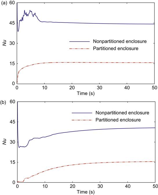
Figure 3.10 shows the profiles of the local Nusselt numbers at the steady state on the partition and two inclined walls of the enclosure. It is clear that the local Nusselt number on the inclined walls is nonuniform and in the upstream section of the walls, it is much larger than that in the downstream section due to the formation of the stratification in the core of the enclosure. However, the local Nusselt number on the partition is approximately constant, but not so at two ends of the partition. The heat transfer through the middle height of the partition does not vary with the height except in the closeness to the top tip and the bottom wall. That means the partition is approximately isoflux at the steady state even though the inclined walls are isotherm, which is an interesting phenomenon at the steady-state condition of the flow. Time series of the overall Nusselt number which are calculated on the inclined walls of the partitioned and nonpartitioned triangular enclosure have been presented in Figure 3.11. It is noticed that the Nusselt number on the left inclined cold wall (Figure 3.11(a)) of the nonpartitioned enclosure is higher at the transitional stage. However, the opposite scenario can be seen in the right heated wall (see Figure 3.11(b)).

3.5 Conclusions
The development of coupled thermal boundary layers between the fluids of two zones in an isosceles triangular enclosure separated by a vertical partition induced by suddenly generated temperature difference between two fluid zones was investigated numerically for different flow parameters. It is revealed from the simulations that the development of the transient boundary layers along the partition are classified into three distinct stages; an initial stage, a transitional stage, and a steady-state stage. The coupled thermal boundary layers start to develop near both sides of the partition as soon as the fluids of two different temperatures reach the partition. At the time when the conduction and convection terms in the energy equation are balanced the flow enters into the transitional stage. The thermal fluids discharged from the downstream ends of the coupled thermal boundary layers continuously fill each half of the partitioned cavity from transition stage to the steady stage. As time progress another thermal boundary layer forms adjacent to the inclined wall. On a close observation of the flow phenomena in the transient process, it may be concluded that the temperature distribution on the partition enclosed by the coupled thermal boundary layers changes from an initially isothermal to an approximately linear profile at the steady state for higher Rayleigh number. As a result, an isoflux condition is set up along the middle portion of the partition in the steady stage. It is found from the numerical simulations that the heat transfer through the coupled thermal boundary layers is higher for lower aspect ratio for a fixed Rayleigh number. However, the heat transfer is higher for larger Rayleigh number for a fixed aspect ratio. It is also found that the heat transfer reduced significantly in the presence of a vertical partition placed in the geometric center line of the enclosure. This concept can be used in domestic houses, especially in Australia, to reduce air-conditioning costs.