
Chapter 5. Component Diagrams
When modeling large software systems it is common to break the software into manageable subsystems. UML provides the component classifier for exactly this purpose. A component is a replaceable, executable piece of a larger system whose implementation details are hidden. The functionality provided by a component is specified by a set of provided interfaces that the component realizes (see "Black-Box View“). In addition to providing interfaces, a component may require interfaces in order to function. These are called required interfaces.
The functionality of a component’s provided interfaces is implemented with one or more internal classifiers. These are typically classes but can be other components (see "White-Box View“). Components should be designed to be reused, with dependencies on external interfaces, strong encapsulation, and high cohesion.
Components
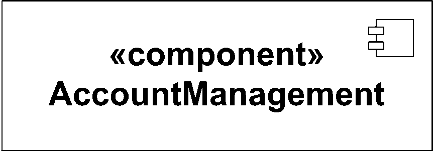
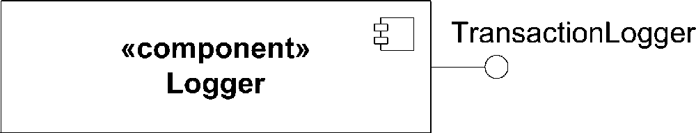
In UML 2.0, you represent a component with the classifier rectangle stereotyped as «component». Like other classifiers, if the details of the component aren’t shown, you place the name of the component in the center of the rectangle. Optionally, you may show the component icon (a rectangle with two smaller rectangles on the left side) in the upper-right corner. Figure 5-1 shows a simple component.
Warning
The representation for a component has changed from previous versions of UML. UML 1.4 recognized a, rectangle with two smaller rectangles:
This notation is still recognized for backward compatibility but is no longer recommended.
Component Dependencies
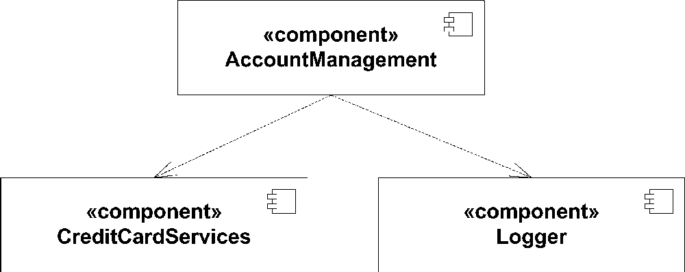
Components may need other components to implement their functionality. You can show component dependencies using the dependency relation (a dashed line with an open arrow) between the two components. Figure 5-2 shows the AccountManagement component dependent on two other components.
Representing component dependencies in this fashion is a relatively high-level view of a system. To further refine the diagram you may want to show inter-component relationships as dependencies on the interfaces provided by other dependent components (see "Black-Box View“; also see "Interfaces" in Chapter 2).
Component Views
UML uses two views of components, a black-box view and a white-box view. The black-box view shows a component from an outside perspective; the white-box view shows how a component realizes the functionality specified by its provided interfaces.
Black-Box View
The black-box view of a component shows the interfaces the component provides, the interfaces it requires, and any other detail necessary to explain the guaranteed behavior of the component. It does not specify anything about the internal implementation of the component. This distinction is central to the concept of replaceable components.
Assembly connectors
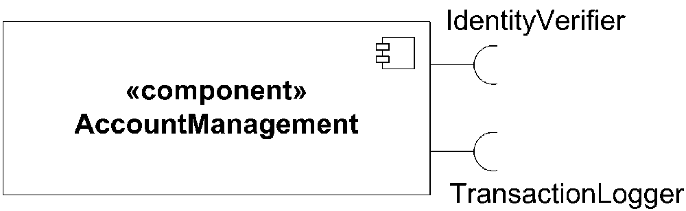
When modeling a black-box view of a component, you represent the provided and required interfaces using assembly connectors . Assembly connectors are illustrated using ball-and-socket icons. To show a required interface, use the socket icon and write the name of the interface near the connector symbol. Figure 5-3 shows a component with two required interfaces.
Show a provided interface with the ball half of an assembly connector, again with the name of the interface near the symbol. Figure 5-4 shows a component with a provided interface.
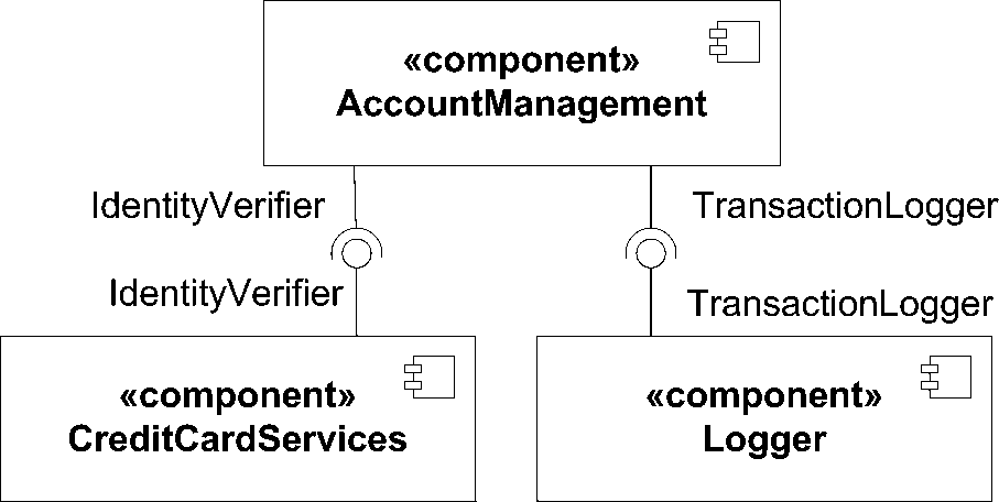
To wire components together, simply connect the matching provided and required interfaces. Component dependencies using assembly connectors provide more details about the actual relationships between components than simple dependency relations. Figure 5-5 shows the same three components from the “Component Dependencies” section, but using assembly connectors.
Interface dependencies
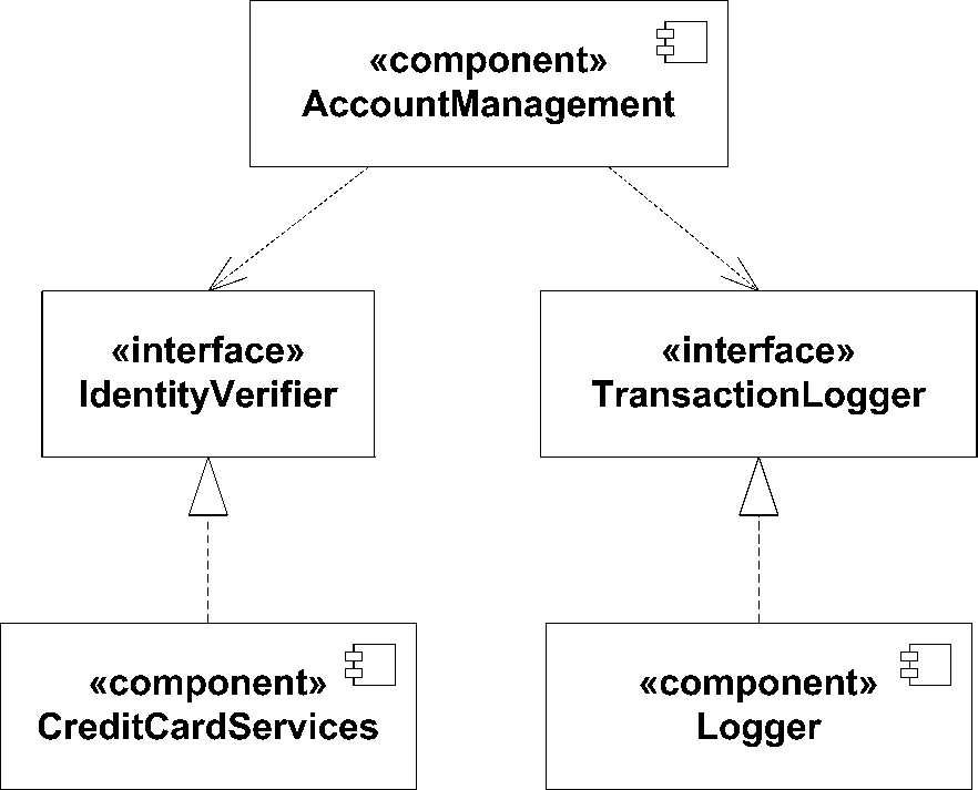
While assembly connectors provide more detail than simple component dependencies, they don’t provide detailed information about the interface that is being realized. UML provides a third black-box representation of components using realization and dependency relationships to interfaces. If a component provides an interface, use a realization arrow from the component to the interface. If the component requires an interface, use a dependency arrow from the component to the required interface. Figure 5-6 shows the same three components as Figure 5-2, but with explicit interface dependencies.
An advantage to the interface dependency style of modeling is that you can attach other modeling elements, such as a state machine or use case, to an interface. This is particularly useful when a component implements a protocol because you can link the provided interface to a protocol state machine to further clarify the component’s usage (see "Protocol State Machines" in Chapter 8).
Component compartments
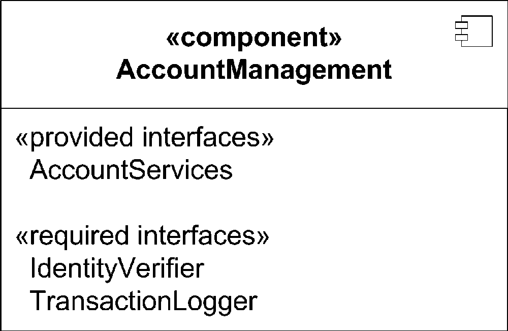
UML also provides a black-box view of components using compartments. You may add a compartment to show provided and required interfaces. Label provided interfaces with the stereotype «provided
interfaces» and required interfaces with the stereotype «required
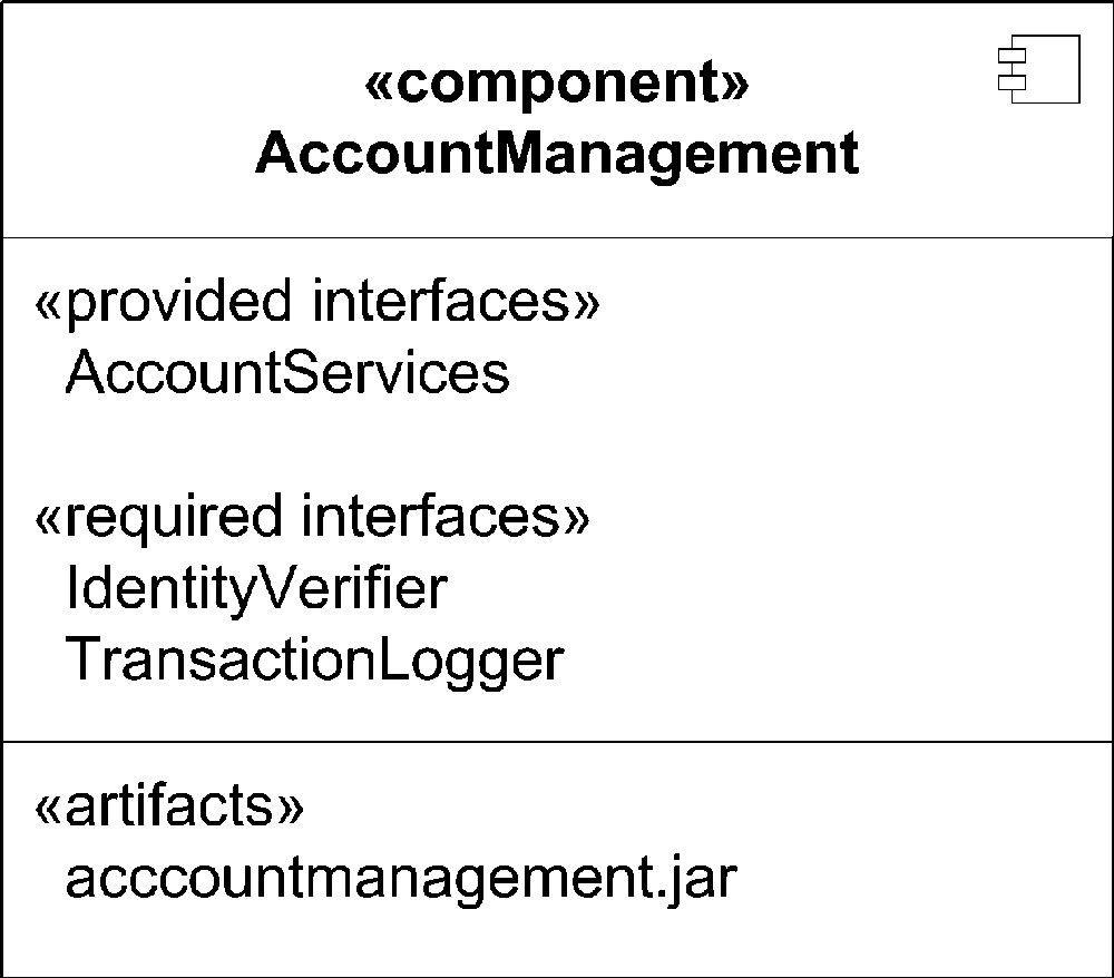
interfaces». Figure 5-7 shows the AccountManagement component using compartments to identify the provided and required interfaces.
UML suggests an additional compartment, stereotyped «artifacts», that can show which artifacts actually implement a component (typically one or more JARs, DLLs, etc.). Figure 5-8 shows a component with an artifact compartment.
White-Box View
In order to provide details about the implementation of a component, UML defines a white-box view . The white-box view shows exactly how a component realizes the interfaces it provides. This is typically done using classes and is illustrated with a class diagram; however a component may delegate some or all of its behavior to other components.
Realization compartment
The simplest white-box view of a component is to add a compartment to the component and list the classifiers that realize it. The compartment should be labeled with the «realizations» stereotype. While this provides more detail than a black-box view, it is of limited use to component developers. Figure 5-9 shows a component with a realizations compartment.
Classifier dependencies
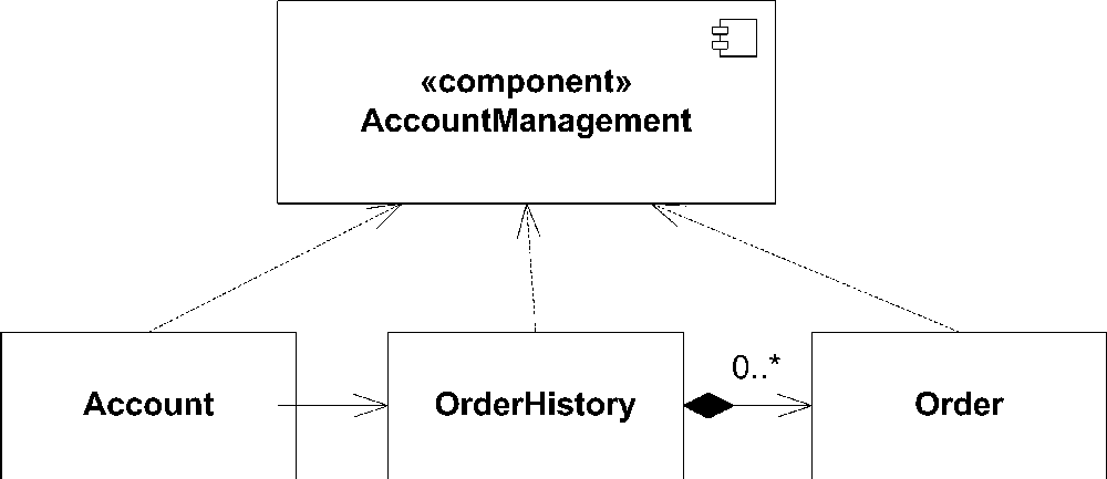
To show the internals of a component, you may show each classifier that realizes a component with a dependency on the component itself. Note that the relationship between the classifiers and the component is a dependency relationship (dashed line, open arrow), not a realization relationship. This notation is useful

for identifying which classifiers make up a component, but the focus of the diagram is still on the component as a whole. Figure 5-10 shows a white-box view of a component and its constituent classifiers.
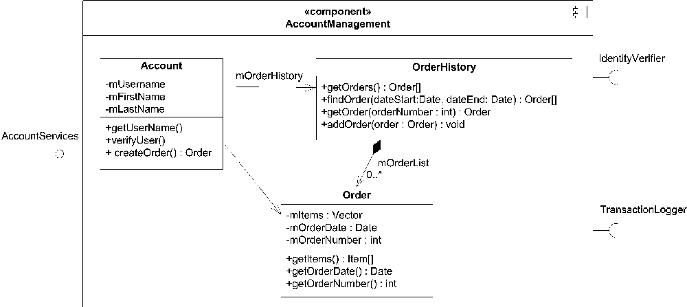
To shift the focus to the structure of the classifiers making up the component, you may show the classifiers inside the component’s rectangle. This tends to have the effect of emphasizing the relationships of the classifiers making up the component, and it encourages component encapsulation. Figure 5-11 shows the detailed realization of a component.
If the internals of a component are sufficiently complex, it is common to use a separate class diagram to model the details. You can link the new class diagram back to its component using a note.
Ports and connectors
UML 2.0 introduces the concept of ports to allow you to explicitly identify functionality that is exposed to the outside world. A port groups together related provided and required interfaces and uses connectors to map them to a classifier that realizes the functionality. If a port has both provided and required interfaces, it is called a bidirectional port. A port is shown as a small rectangle on one of the sides of a classifier. An assembly connector (ball and socket) indicates provided and required interfaces.
In order to show the realization of functionality, a connector maps the port to an internal classifier. A connector is shown as a solid line with a filled arrow from the port to the classifier. A connector indicates that any messages arriving at the port (typically in the form of method calls) are forwarded to the specified classifier. You can also use connectors from a classifier to a port to show messages being passed through a provided interface. Figure 5-12 shows a white-box view of a component with three ports.
Component Stereotypes
UML defines several stereotypes that apply specifically to components:
- Entity
A component that represents a business concept. An entity component typically passes information in and out of interfaces and is often persisted as a whole. Entities don’t typically have any functionality, or service capabilities, associated with them; they are usually just for data storage and retrieval.
- Process
A component that can fulfill functional requests (as opposed to an entity component). A process component is transaction-based and typically has some type of state associated with it (as opposed to stateless service components).
- Realization
A component that doesn’t have its own specification. Rather it is a realization of a specification component, as shown in Figure 5-13.

- Service
A stateless component that can fulfill functional requests. Service components are rarely persisted because they contain no state.
- Specification
A component that has provided and required interfaces but no implementation (realizing classifiers). A specification component, shown in Figure 5-13, should be paired with a realization component or implement component.
- Subsystem
A larger component that makes up part of a bigger software system. UML provides no real definition for a subsystem; however, subsystem generally means a self-contained set of functionality that is larger than a simple component.