Chapter 3. Package Diagrams
Packages provide a way to group related UML elements and scope their names. For example, you can put all elements having to do with 3D rendering into a package named 3DGraphics. Package diagrams provide a great way to visualize dependencies between parts of your system and are often used to look for problems or determine compilation order.
Nearly all UML elements can be grouped into packages, including packages themselves. Each package has a name that scopes each element in the package. For example, if you had a class named Timer in a package named Utilities, the fully qualified name for the class is Utilities::Timer. Elements in the same package can refer to each other without qualifying their names.
Representation
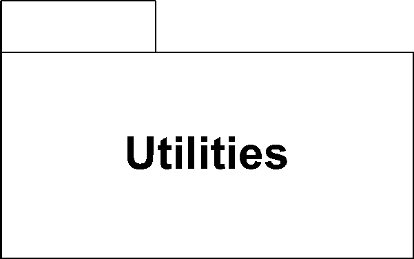
You show a package using a rectangle with a tab attached to the top left. Figure 3-1 shows the Utilities package.
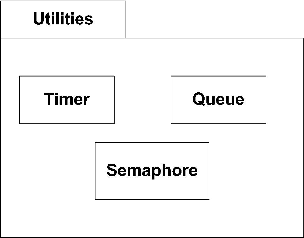
You can show the elements contained within a package in two different ways. First, you can show the elements contained within the package by drawing them inside the large rectangle. If you use this representation
, write the name of the package in the tab. Figure 3-2 shows the contents of the Utilities package inside of the package. To refer to the Timer class from outside of the Utilities package, you say Utilities::Timer.
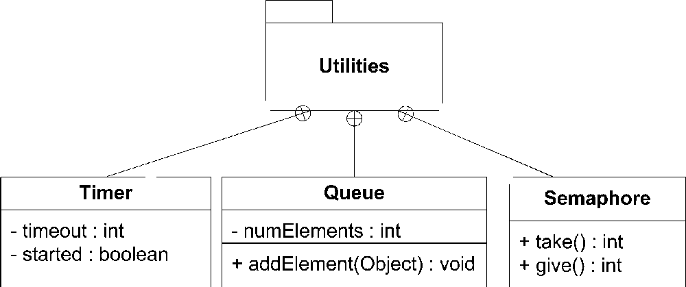
The second representation
uses a solid line pointing from the package to each contained element. You place a circle with a plus sign in it at the end nearest the package to indicate containment. If you use this representation, you should show the name of the package in the large rectangle rather than in the tab. This notation allows you to show more detail of the packaged elements. Figure 3-3 shows the same Utilities package but with the classes broken out.
You don’t need to show all the elements contained within a package; if no elements are shown, no assumptions can be made about what the package contains.
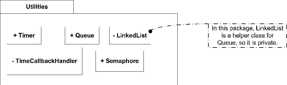
Visibility
A package may specify visibility information for owned and imported elements, however elements may have only one of two levels of visibility: public or private. Public visibility means the element may be used outside the package (scoped by the package name). Private visibility means the element may be used only by other elements of the same package. Private visibility is useful for marking utility classes that help implement a subsystem or component you don’t want to expose to the rest of the system.
You show public visibility
by placing a plus sign before the element name. You show private visibility using a minus sign. Figure 3-4 shows the Utility package with some private helper classes.
Importing and Accessing Packages
When accessing elements in one package from a different package, you must qualify the name of the element you are accessing. For example, if Car is a class in the Transportation package and you are trying to access it from a package named RoutePlanning, you need to qualify Car as Transportation::Car.
To simplify accessing elements in a different package, UML allows a package to import another package. Elements of the imported package are available without qualification in the importing package. So, if the RoutePlanning package imported the Transportation package, you can refer to Car without any qualifications from within the RoutePlanning package.
To show a package import, you draw a dashed line with an open arrow from the importing package to the imported package. Label this line with the «import» keyword. Figure 3-5 shows the RoutePlanning package importing the Transportation package.

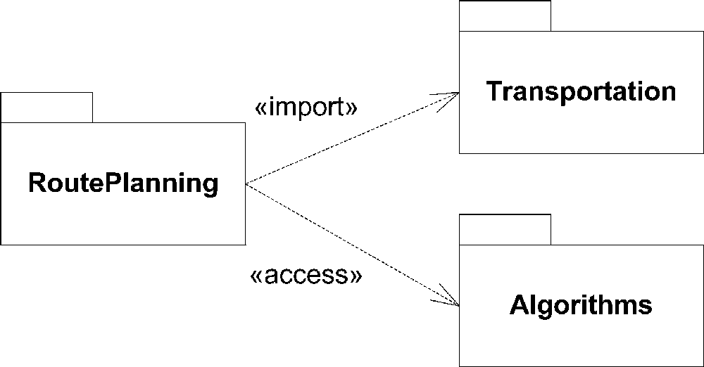
By default, imported elements are given public visibility in the importing package. UML allows you to specify that imported elements should be given private visibility, meaning they can’t be used by anyone outside the importing package (including any packages that may import that package). To specify that imported elements should have private visibility, you use the «access» keyword rather than the «import» keyword. Figure 3-6 shows the RoutePlanning package importing the Transportation package and accessing the Algorithms package. If a package imports the RoutePlanning package, both packages can use public elements from Transportation, but they can’t use anything in Algorithms.
What package import and access actually mean in implementation can vary dramatically depending on your target language. For example, C# and Java have an explicit concept of packages and importing elements from packages. Java developers often import the java.util package into their program so they can reference the Java Vector class without qualifying it. However, C++ has a somewhat subtler concept of packages, called namespaces. How packages map to an implementation language is often up to the implementer.
Merging Packages
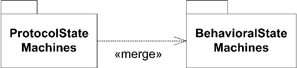
UML supports a somewhat complex concept of merging packages. Merging packages differs from importing packages in that merge, by definition, creates relationships between classes of the same name. The motivation behind package merging comes directly from the evolution of UML from 1.x to 2.0. UML 2.0 defines the base concept of elements and allows specific diagram types to extend a base concept without needing to provide a new name for it. For example, UML extends several core Behavioral State Machine concepts into Protocol State Machine concepts while retaining their original name.
When a package merges another package, any class of the same type and name automatically extends (or has a generalization relationship to) the original class. For example, UML can define the concept of the include relationship at a generic level and then specialize it for use cases inclusion and retain the name include. This type of extension has simplified the internals of the UML model but rarely makes an appearance in real-world development.
You show package merging using a dashed line with an open arrow from the merging package to the merged package. Label this line with the keyword «merge». Figure 3-7 shows an example of merging two packages.
The rules for package merge are:
Private members of a package aren’t merged with anything.
Classes in the package performing the merge that have the same name and type as classes in the merged package(s) get a generalization relationship to the merged class(es). Note that this can result in multiple inheritance, but UML allows this.
You can still reference any of the original classes by explicitly scoping the class using the original package name.
Classes that exist only in the merged package or the merging package remain unchanged and are added to the merging package.
Subpackages within the merged package are added to the merging package if they don’t already exist.
If a subpackage with the same name already exists in the merging package, another merge is started between the two subpackages.
Any package imports from the merged package become package imports from the merging package. Elements that are imported aren’t merged (i.e., aren’t given generalization relationships). If an imported element conflicts with an element in the merging package, the merging package’s element takes precedence and the imported element must be explicitly qualified.
Variations on Package Diagrams
This section presents two applications of class package diagrams and one application of use case packages. Although layering and simplification always motivate packaging, the term “simplification” means different things to different people. Simplification can mean:
Easier to build and test
Better tracking and project transparency
Working at a stable overview without the noise of low-level churn
Less conflict between distributed teams
Easy refactoring and extension
Simplification likely means more apparent complexity to some constituency. Unless your packaging balances these diverse needs, you are likely to receive complaints of unnecessary complexity, no matter how noble your motives are.
Structuring a Project with Package Diagrams
Class packages organize a logical system during construction. They provide the terms for management and external stakeholders, as well as structure to contain all classes and code to be built. Class package diagrams are the UML equivalent of block diagrams.
Different parties think of a project according to their different needs. Programmers think in terms of language and tactical design. Architects think in terms of dependencies, risk, technology, building, testing, and OO principles. Project managers think in terms of risk, tracking, resources, need, ownership, required skills, and delivery. Although all issues are important, and good packaging recognizes its responsibility to all needs, architects tend to identify top-level packaging with an eye on the control functions of project management. For example, a project manager might draw a package diagram for a web application such as that shown in Figure 3-8.
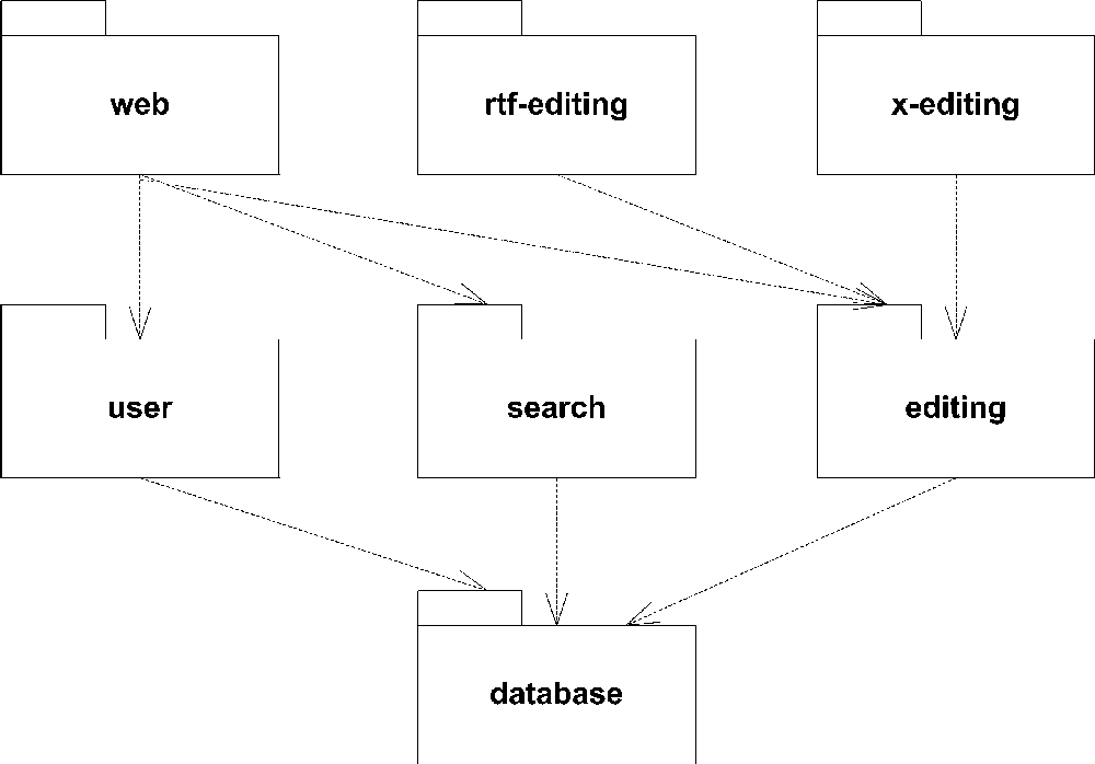
The diagram in Figure 3-8 carries very little meaning by itself. It must be accompanied by an auxiliary, textual document that describes the basis for the packaging. Such a document might, for example, contain a list as follows:
-
web Requires special skills: HTML, CSS, and Struts, a presentation technology; most dependencies.
-
database Requires database management and modeling skills; most independent/fewest dependencies.
-
user To be built off-site by a remote team.
-
search Requires familiarity with search engine technology and techniques; self-contained subsystem.
-
editing Comprises the basic editing features to be delivered in the first release; different skills and different team.
-
rtf-editing Comprises those editing features scheduled for release 2.
-
x-editing Comprises editing features requested by a specific client. These features to be withdrawn or delayed depending on that client. Risk is independent of the other features.
Figure 3-8 doesn’t show the complete set of packages in the system. It is merely enough for management to track and control the project. Programmers create lower-level packages as needed for correct code design. Managers, however, allocate resources and track progress on the relatively large grains of the project shown in Figure 3-8 without getting disturbed by the addition or refactoring of internal packages and contents.
Use Case Packages
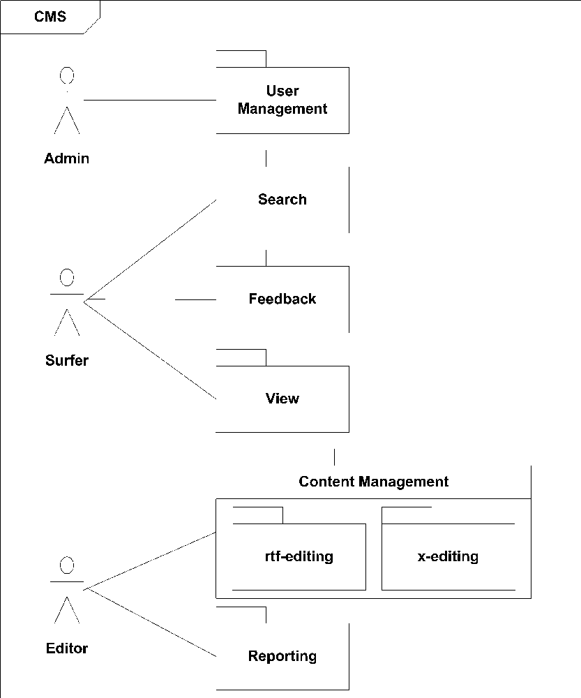
Use case packages organize the functional behavior of a system during analysis. Figure 3-9 shows the major functional areas of a content management system. The packages provide understandable terms for team members outside the analyst team. Managers can discuss the project at an appropriate level of detail without getting bogged down in details.
The CMS system shown in Figure 3-9 comprises packages created for the following reasons:
The complex editing packages separate the preliminary delivery and the advanced delivery from the client-based delivery.
The simple interactions, view and feedback, contain basic, low-risk functions.
The reporting has more sophisticated functions.
The search and the user management separate complex functions.
Just as with the class packages in Figure 3-8, you manage the use case packages to manage the project. Remember that tracking use case packages tracks customer value.
Directed Dependency Graphs
Directed dependency graphs of the packages in a system reveal nonfunctional issues related to buildability, testability, and robustness; they provide a guide for several roles in software development.
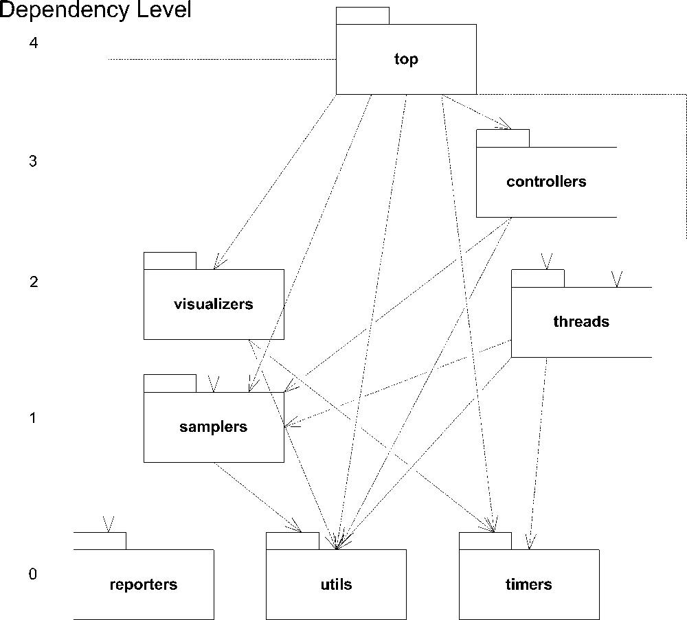
When all the dependencies flow in one direction, as in Figure 3-10, without any loops or cycles, the graph is acyclic. Acyclic graphs show a project in good health.
Directed dependency graphs can help you avoid problems with build scripts and project testing. Looking at Figure 3-10, you can see that refactoring timer will invalidate testing and potentially break the build of visualizers, threads, controllers, and top; you should thus change the timer package with caution.
Directed dependency graphs can also help you divide project work among different staff members. For example, Figure 3-10 shows no dependencies between threads and visualizers. Thus, different groups of people can work on those two packages without destabilizing each other.
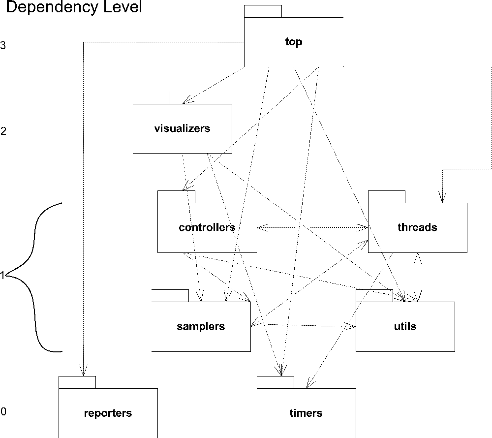
Through time, projects evolve, and new dependencies creep in because of misunderstanding or expediency. Figure 3-11 shows such a case; three bidirectional dependencies ruin the desirable, acyclic nature of the graph:
utilsnow depends onthreads.threadsnow depends oncontrollers.samplersnow depends onthreads.
The problem here is that the reverse of each dependency already existed in Figure 3-10. The result is the tangle of bidirectional arrows in level 1 of Figure 3-11, which contrasts with the clear flow of arrows in Figure 3-10. The further result is pain, for the developers, testers, and likely, managers and users. Changes in threads will confound the team responsible for controllers and utils, and vice versa because fixes in one require fixes in the code or unit tests of the others. It may take several iterations until all packages stabilize.[*]
[*] For more theory and metrics regarding packages and their dependencies, see John Lakos’ Large-Scale C++ Software Design. Also see Robert C. Martin’s http://c2.com/cgi/wiki?PrinciplesOfObjectOrientedDesign.