Chapter 7. Use Case Diagrams
Use cases are a way to capture system functionality and requirements in UML. Use case diagrams consist of named pieces of functionality (use cases ), the persons or things invoking the functionality (actors), and possibly the elements responsible for implementing the use cases (subjects ).
Use Cases
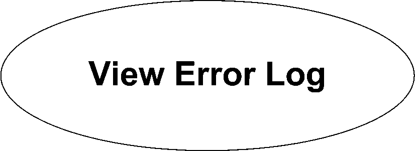
Use cases represent distinct pieces of functionality for a system, a component, or even a class. Each use case must have a name that is typically a few words describing the required functionality, such as View Error Log. UML provides two ways to draw a use case. The first is an oval with the name of the use case in the center. Figure 7-1 shows a basic use case.
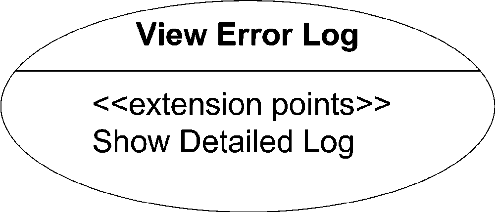
You can divide a use case’s oval into compartments to provide more detail about the use case, such as extension points (see "Use Case Extension“), included use cases (see "Use Case Inclusion“), or the modeling of specific constraints. Figure 7-2 shows a use case oval with a compartment listing extension points.
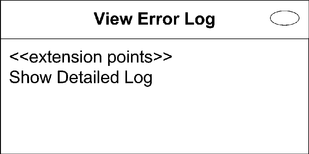
However, the oval representation of use cases doesn’t hold up well with detailed compartments. UML recommends you use the classifier notation if you want to provide details about a use case. Show the use case as a rectangle, with the use case oval in the top-right corner. Now, place the name of the use case in the top, in bold. You can then divide the classifier into compartments as needed. Typical
compartment names are extension points and included use cases
. Figure 7-3 shows the same use case as in Figure 7-2, but in classifier notation.
UML makes a clear distinction that the term use case strictly applies to the UML element and its name. Full documentation of a use case is considered an instantiation of the use case. This is a subtle distinction, but it allows you to document a use case whatever way best captures the use case’s functionality. You can document a use case in a text document, state machine, interaction diagram, activity diagram, or anything else that conveys the details of the functionality in a meaningful way to your reader.
Actors
A use case must be initiated by someone or something outside the scope of the use case. This interested party is called an actor. An actor doesn’t need to be a human user; any external system or element outside of the use case may trigger the use case (or be the recipient of use case results) and should be modeled as an actor. For example, it is very common to model the system clock as an actor that triggers a use case at a given time or interval.
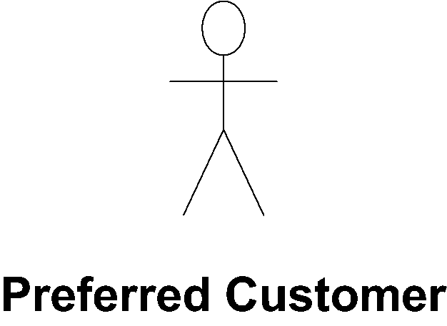
An actor can have several different representations in UML. The first is a stick figure with the name of the actor written near the icon (usually right below it). Figure 7-4 shows an actor icon.
Alternatively, an actor can be shown using the classifier notation. You represent the actor with a rectangle, with the keyword actor at the top and the name of the actor in bold immediately below that. Because actors don’t typically have compartments, this representation isn’t used very often. Figure 7-5 shows an actor in classifier notation.
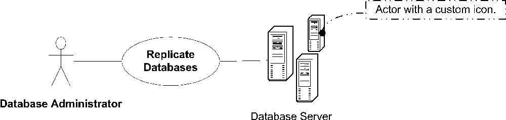
If it is helpful, you may use custom icons to clearly distinguish different types of actors. For example, you can show an external database system using a database

icon while showing the system administrator as a stick figure. Figure 7-6 shows exactly this set of actors.
Actor/Use Case Associations
You typically associate an actor with one or more use cases. A relationship between an actor and a use case indicates the actor initiates the use case, the use case provides the actor with results, or both. You show an association between an actor and a use case as a solid line. Conventionally you read use case diagrams from left to right, with actors initiating use cases on the left and actors that receive use case results on the right. However, depending on the model or level of complexity, it may make sense to group actors differently. Figure 7-7 shows an actor communicating with a use case.

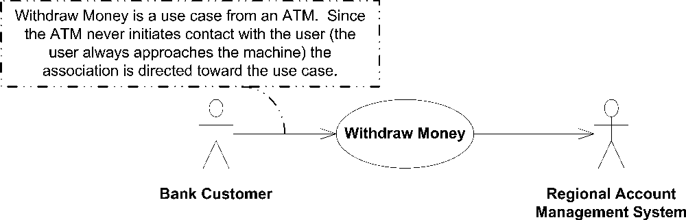
Though not part of the official UML specification, it is common to see directional arrows on association lines to indicate who initiates communication with whom. Note that the arrows don’t necessarily restrict the direction of information flow; they simply point from the initiator to the receiver of the communication. What happens after a use case begins execution is specified elsewhere (see "Use Cases“). Figure 7-8 shows two actors and a use case with directional associations.
System Boundaries
By definition, use cases capture the functionality of a particular subject. Anything not realized by the subject is considered outside the system boundaries and should be modeled as an actor. This technique is very useful in determining the scope and assignment of responsibilities when designing a system, subsystem, or component. For example, if while you are modeling an ATM system, your design discussions digress into discussions of the details of the back-end banking system, a use case model with clearly defined system boundaries would identify the banking system as an actor and therefore outside the scope of the problem.
You represent system boundaries in a generic sense using a simple rectangle, with the name of the system at the top. Figure 7-9 shows the system boundaries for the ATM machine mentioned in the previous paragraph.
Using Actors to Identify Functionality
Actors don’t need to have a one-to-one mapping to physical entities; in fact, they don’t need to be physical entities at all. UML allows for actors to represent roles of potential users of a system. For example, the system administrator may be the only physical user of a system, but that administrator may wear many hats. It may be helpful to view the system from the perspective of a database administrator, backup administrator, deployment administrator, and so on. By specifically identifying the various roles of actors that may use the system, you can often discover use cases that would have gone unnoticed. Figure 7-10 shows a sample diagram containing three types of administrators and example use cases.


Advanced Use Case Modeling
As it does for other classifiers, UML provides mechanisms for reusing and adding on to use cases and actors. You can expand an actor’s capabilities or replace entire use cases using generalization . You can factor out common elements of use cases using included use cases, or add on to base use cases using use case extension.
Actor and Use Case Generalization
Though not officially mentioned in the specification, actors and use cases can be generalized like many other classifiers. Actor generalization is typically used to pull out common requirements from several different actors to simplify modeling. For example, Figure 7-10 shows several administrators and the use cases they need to invoke. You may have a Database Administrator, a Backup Administrator, and a Deployment Administrator, all with slightly different needs. However, the majority of the needs of the individual actors may overlap. You can factor out a generic System Administrator actor to capture the common functionality, and then specialize to identify the unique needs of each actor.
You represent actor generalization like any other classifier; draw a solid line, with a closed arrow pointing from the specialized actor to the base actor. Figure 7-11 shows the same information as Figure 7-10 but in a much easier-to-read diagram.
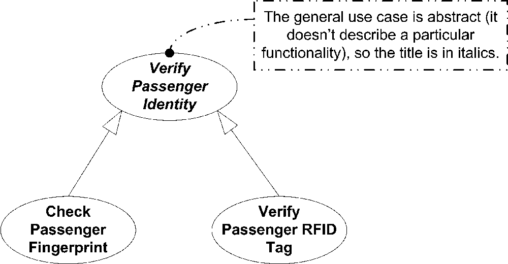
Use cases may be generalized as well. Typically use case generalization is used to express some high-level functional need of a system without going into specifics. Specializations of a general use case introduce specific functionality. For example, a generic use case can be Verify Passenger Identity, and specializations of that use case can be Check Passenger Fingerprint and Verify Passenger's RFID Tag. It is important to notice that even with use case generalization, you should still discuss functionality, not implementation. You should not have specializations of a use case for different ways to implement the same functionality, only to represent different functionality.
You represent use case generalization just like you do actor generalization: using a solid line, with a closed arrow pointing from the specialized use case to the base use case. If the general use case represents abstract functionality (meaning it’s a functional concept but doesn’t actually explain how a user would do something), you show the name of the use case in italics. Figure 7-12 shows the verification use cases and their relationships.
Use Case Inclusion
You can factor out common functionality from several use cases by creating a shared, included use case. Unlike in use case extension (discussed next), the use case that includes another use case is typically not complete on its own. The included functionality isn’t considered optional; it is factored out simply to allow for reuse in other use cases.
You show use case inclusion using a dashed line, with an open arrow (dependency) pointing from the base use case to the included use case. Label the line with the keyword include. Figure 7-13 shows an example of use case inclusion.


Use Case Extension
UML provides the ability to plug in additional functionality to a base use case if specified conditions are met. For example, if you are modeling a banking application, you can have a use case named Open Account that specifies how the user can create a new account with the bank. You can offer a joint account that allowed a user to add other people to his account. The joint account functionality can be captured with a different, use case named Add Joint Member. In this case the specified condition for the extension is more than one member on the bank application.
UML clearly specifies that a base use case should be a complete use case on its own. The extension use cases are typically smaller in scope and represent additional functionality, so they may not be useful outside the context of the base use case.
Any use case you want to extend must have clearly defined extension points . An extension point is a specification of some point in the use case where an extension use case can plug in and add functionality. UML doesn’t have a particular syntax for extension points; they are typically freeform text, or step numbers if the use case functionality is represented as a numbered list.
You list extension points in a use case oval, or in a separate compartment when using the classifier notation. Figure 7-14 shows a use case with extension points.

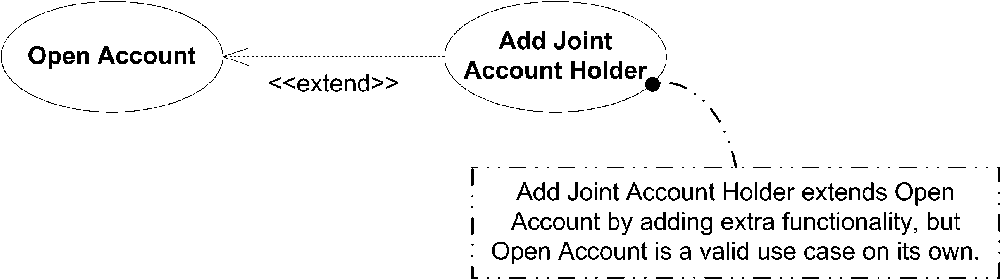
You represent a use case extension by showing a dashed line, with an open arrow (dependency) pointing from the extension use case to the base use case. Label the line with the keyword extend. Figure 7-15 shows an example of use case extension.
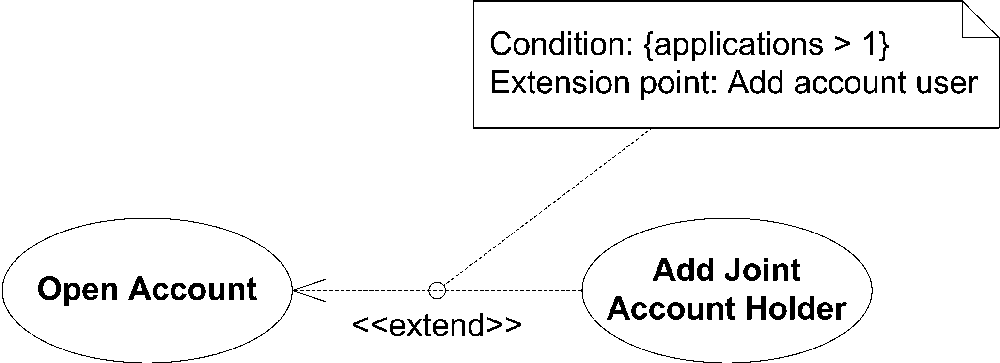
To provide more detail you can specify where the new functionality plugs into the base use case by specifying an extension point and a note attached to the dependency line. Optionally you can specify under what condition the extension executes, such as applicants > 1. Figure 7-16 shows use case extension with a note specifying the extension point and the condition to execute the extra functionality.
When the system encounters an extension point in a use case, any conditions associated with extension use cases are evaluated. If a condition is met, the corresponding extension functionality is executed. Once all appropriate extension use cases have been executed, the base use case continues with the next step in the original flow.
Use Case Scope
As mentioned previously, a use case is a distinct piece of functionality, meaning it is of sufficient granularity that the user has accomplished his desired goal. Proper scoping of use cases is an art, but UML sets several requirements to make the job a little easier:
A use case must be initiated by an actor.
When a use case is considered complete, there are no further inputs or outputs; the desired functionality has been performed, or an error has occurred.
After a use case has completed, the system is in a state where the use case can be started again, or the system is in an error state.
One popular rule of thumb is to ask yourself if the user can “go to lunch” after completing the use case, meaning that a reasonably sized goal has been achieved by the initiator. For example, Add item to shopping cart is probably not the larger goal a user intends; Purchase item is likely a better scope. Purchase item can consist of adding an item to a shopping cart but typically has more functionality such as logging on, entering billing and shipping information, and confirming the order.
Above all, use cases are intended to convey desired functionality, so the exact scope of a use case may vary depending on the intended audience and purpose for modeling.