
Chapter 10. Interaction Diagrams
A fundamental goal of UML 2.0 is to allow users to capture more than just structural relationships. UML 2.0 is intended to capture processes and flows of events. Interaction diagrams draw from nearly every other facet of the language to put together a set of diagrams that capture communications between objects. UML 2.0 has greatly expanded UML 1.x’s ability to describe complex flow of control; one of the largest sections of the UML 2.0 specification is the interaction diagrams section. Because of the expanded functionality, quite a bit of new terminology has been introduced. We’ll cover all the terms in this chapter and try to give you a feel for what terms are really critical and which are there to formalize the specification.
What Are Interactions?
Interaction diagrams are defined by UML to emphasize the communication between objects, not the data manipulation associated with that communication. Interaction diagrams focus on specific messages between objects and how these messages come together to realize functionality. While composite structures show what objects fit together to fulfill a particular requirement, interaction diagrams show exactly how those objects will realize it.
Interaction diagrams are typically owned by elements in the system. For example, you may have an interaction diagram associated with a subsystem that shows how the subsystem realizes a service it offers on its public interface. The most common way of associating an interaction diagram with an element is to reference the interaction diagram in a note attached to the element.
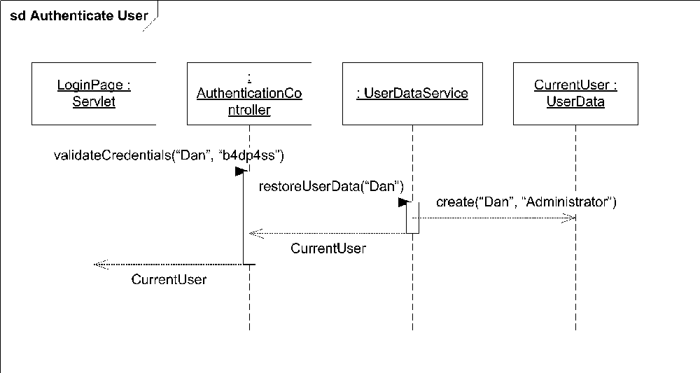
You can show the details of an interaction using several different notations; however sequence diagrams are by far the most common. Other notations include interaction overviews, communication diagrams, timing diagrams, and interaction tables. Because sequence diagrams are used most frequently, each concept is introduced using that notation. The other notations are described in detail later in the chapter. The basic symbol for an interaction diagram is a rectangle with the keyword sd and the name of the interaction in a pentagon in the upper-left corner. Figure 10-1 shows an example sequence diagram. The various parts of this diagram are explained throughout the chapter.
Interaction Participants
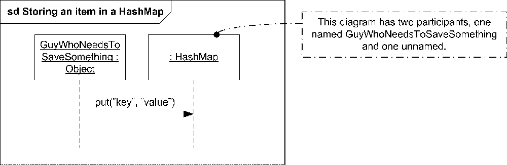
You show participants in an interaction using a rectangle called a lifeline. The term lifeline illustrates UML’s bias toward representing interaction diagrams using the sequence diagram notation. When shown in sequence diagrams, participants have a dashed line dropping down from a rectangle that shows how long the object is actually in existence. When used in other interaction diagram notations, such as communication diagrams, a lifeline is simply a rectangle. You show the name of the participant in the rectangle using the following notation:
object_name[selector] :class_namerefdecomposition
where:
-
object_name Specifies the name of the instance involved in the interaction.
-
selector Is an optional part of the name that can identify which particular instance in a multivalued element is to be used (for example, which
EventHandlerin an array ofEventHandlers).-
class_name Is the name of the type of this participant.
-
decomposition Is an optional part of the name that can point to another interaction diagram that shows details of how this participant processes the messages it receives (see "Decomposition“).
UML defines a reserved participant name, self, that indicates the participant is the classifier that owns this interaction diagram.
Figure 10-2 shows a trivial interaction diagram with two participants and a message between them.
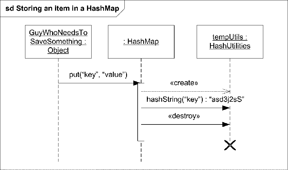
You can show the destruction of a participant during an interaction using a stop symbol. Typically this is preceded by a «destroy» message to the object, though that isn’t strictly necessary. Place an X at the bottom of the lifeline where the object ceases to exist. Figure 10-3 shows destroying a helper class after it has finished its work.
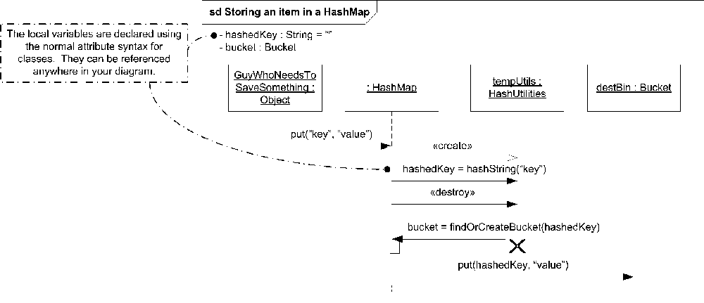
To help make your sequence diagram accurately capture the behavior you are trying to model, you can introduce local variables
. Local variables can hold return values, loop information, or just data you need for later processing. You show the values of local attributes relevant to the interaction using the same attribute syntax used inside of classifiers (see Chapter 2). Place their name and values in the upper left of the diagram, or in a note attached to the diagram. Figure 10-4 shows a more detailed version of the HashMap interaction using local variables.
In addition to local variables, sequence diagrams can access data in the participants. See "Messages" for examples.
Messages
The focus of interaction diagrams is on the communication between lifelines. This communication can take many different forms: method calls, sending a signal, creating an instance, destroying an object, etc., all of which are collectively called messages
. A message specifies the kind of communication, its sender, and its receiver. For example, a PoliceOfficer class instantiating a SpeedingTicket class is represented as a message from an instance of PoliceOfficer to the newly created instance of SpeedingTicket.
The most common use of messages is to represent method calls between two objects. When messages are used to indicate a method call, you can show the parameters passed to the method in the message syntax. The parameters should be one of the following:
Attributes of the sending object
Constants
Symbolic values (expressions showing what the legal values can be)
Explicit parameters of the enclosing interaction
Attributes of the class owning the enclosing interaction
The syntax for a message is:
attribute=signal_or_operation_name(arguments) :return_value
where:
-
attribute Is an optional part of the syntax that provides a shorthand way of showing that the return value from this message is stored in the specified attribute. The attribute must be an attribute of the lifeline sending the message, a global attribute of the interaction, or an attribute of the class owning the interaction.
-
signal_or_operation_name Specifies the name of the operation to invoke or the signal being emitted.
-
arguments A comma-separated list of arguments to pass to the operation or signal. The arguments may be values or parameter names. If only argument values are used, arguments are matched against the operation or signal signature, in order. If you want to skip an argument, place a dash (-) where the argument would be. Skipped arguments have unknown values. You can explicitly identify a parameter name by following the text name with a colon (:) and then the value. If you use parameter names, you can omit arguments not relevant to the interaction. As with a dash, skipped arguments have unknown values.
You can prefix an argument with the keyword
outorinoutto indicate the argument is used to return a value. If the argument is used as anoutargument, a value after the colon in the argument specification is interpreted to be the return value.-
return_value Explicitly states what the return value from this message will be.
Message notation varies based on the specific notation you use to show the details of the interaction. Because the most common representation of interactions is with sequence diagrams, you use the notation that’s common with such diagrams. See the specifics about other notations in “Alternate Interaction Notations.”
When using sequence diagram notation, you show a message as a solid line pointing from the sender’s lifeline to the receiver’s lifeline. If the message is an asynchronous message (meaning the caller doesn’t block waiting for the receiver to process the message), you place an open arrowhead on the receiver’s end of the line. Figure 10-5 shows an example of an asynchronous message.
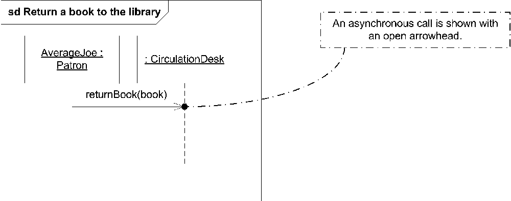
When returning a book to the library, you typically don’t wait around for the librarian to return the book to the shelves. Instead, you drop the book off at the Circulation Desk and continue on your way. The open arrowhead indicates that the caller (AverageJoe) doesn’t wait for any response from the CirculationDesk.
Because asynchronous messages don’t require the sender to wait for a message to be delivered, depending on the transport mechanism, asynchronous messages can arrive out of order. For example, two network packets can take different routes to the same destination, with the second arriving before the first. You can show out-of-order reception by having the first message point to a spot below the reception point of the second message, as shown in Figure 10-6.
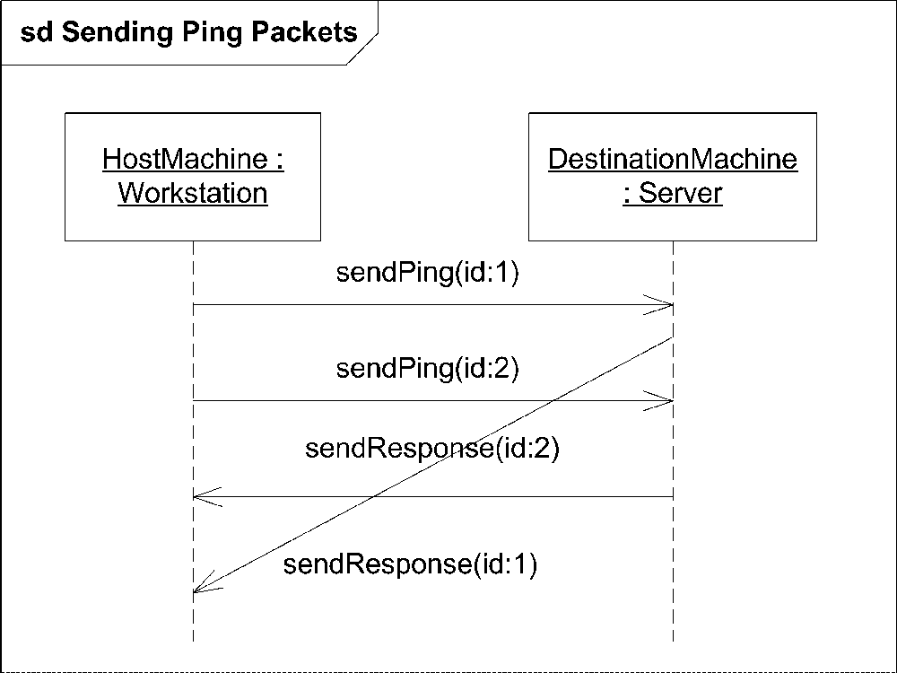
In this example HostMachine sends two ping packets to DestinationMachine. Because of network differences in the routes taken, the response to the second ping arrives before the response to the first ping.
If a message represents synchronous communication (typically a method call), you place a filled arrow head on the receiver’s end. You can show return values from a method using a dashed line with an open arrowhead pointing back to the caller. Figure 10-7 shows a method call to order an item and a confirmation number sent back as a return value.
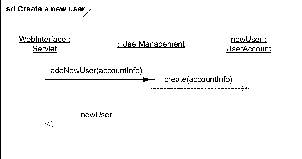
If a message represents object creation, you show a dashed line, with an open arrow pointing to the newly created object’s lifeline. By convention, the message is typically labeled with some variation of create. If there are no arguments to the message, you can simply label the message with the keyword «create», as in Figure 10-3. If there are arguments, you show them as parameters to a create() message. If there is a particular reason to show the creation message using a different label (such as a factory method), you should use that. Figure 10-8 shows an example that creates an instance of the class UserAccount.

Although this technique isn’t mentioned in the specification, some modelers prefer to lower the rectangle representing the object to the end of the message line to clearly indicate the object didn’t exist before this creation event. The advantage of this notation is that it clearly shows when the object comes into existence; the disadvantage is that you can’t skim the top row and view the participants. Figure 10-9 shows the same diagram but lowers the newly created object.
UML defines two special types of messages: lost messages and found messages . Lost messages are messages that are sent but never reach their destination. Found messages are messages that are received by an object but the sender is unknown. For example, if you want to model an exception-handling mechanism, the sending of the exception is really irrelevant to the mechanism itself, so you can model that as a found message. Understand that unknown senders and receivers are relative concepts. The sender or receiver of a message may be unknown as far as a

particular interaction is concerned, meaning it’s really outside the scope of what you are trying to show, not that the message necessarily vanishes from existence (though that’s permissible too).
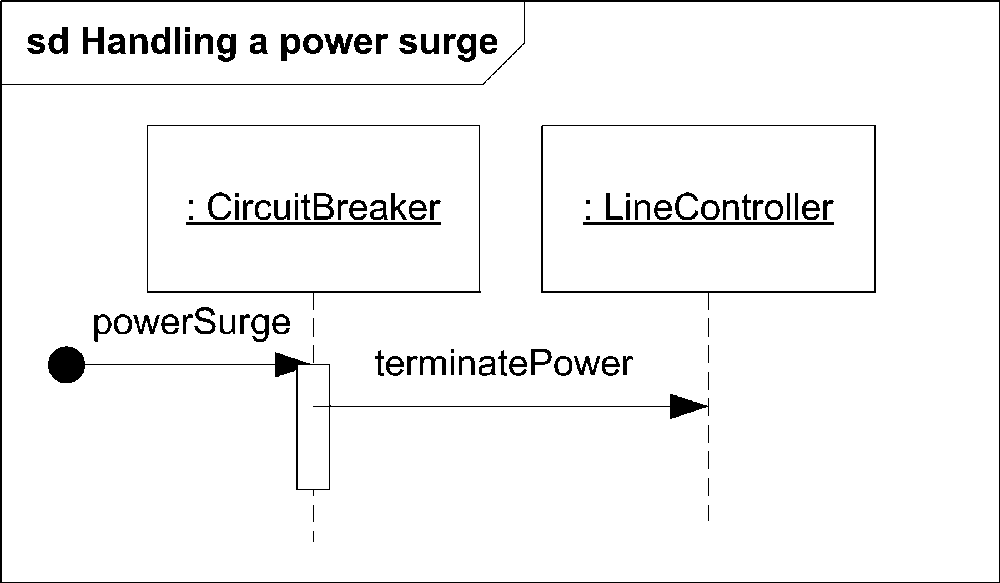
You show a found message by starting the message from a black circle rather than the sender’s lifeline. Figure 10-10 shows an example of a found message. The CircuitBreaker doesn’t care where the power surge came from; it must terminate the power in all conditions.
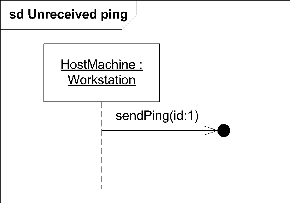
Similarly, you show a lost message by terminating the message arrow at a black circle rather than a receiver’s lifeline. Figure 10-11 shows a Workstation sending out a ping message that for some reason, (network failure) isn’t received.
Execution Occurrences
You can show an object is involved in executing some type of action (typically a method call) for a measurable amount of time using an execution occurrence. Execution occurrences are shown as gray or white rectangles on a lifeline. In practice, it is common to hear execution occurrences called “focus of control,” because they indicate that an object is busy (has the focus of the system) for some period of time. Figure 10-12 shows several execution occurrences in response to messages.
While not officially part of the specification, it was a common practice in UML 1.x to show messages starting from an execution occurrence on a lifeline to indicate that an object will send messages to other objects as part of processing a received message. With UML 2.0, it may be more appropriate to show a set of messages as an interaction fragment. Using interaction fragments, an appropriate interaction operator, and a reasonable name, you have much greater flexibility in expressing exactly how a piece of the system executes and how it fits into the bigger picture. See "Combined Fragments" for more information on interaction fragments and the various ways you can organize messages to increase your diagram’s readability.
State Invariants
UML allows you to place labels along a lifeline to convey conditions that must be true for the remainder of the interaction to be valid. These conditions are called state invariants . State invariants are typically boolean expressions, though they may be full UML states (see Chapter 8). For example, you may have a series of messages that initialize a participant. After the messages have completed, the participant must be in a well-known state for the remainder of the interaction to complete successfully. You can enforce that by placing a state invariant on your diagram after the initialization messages.
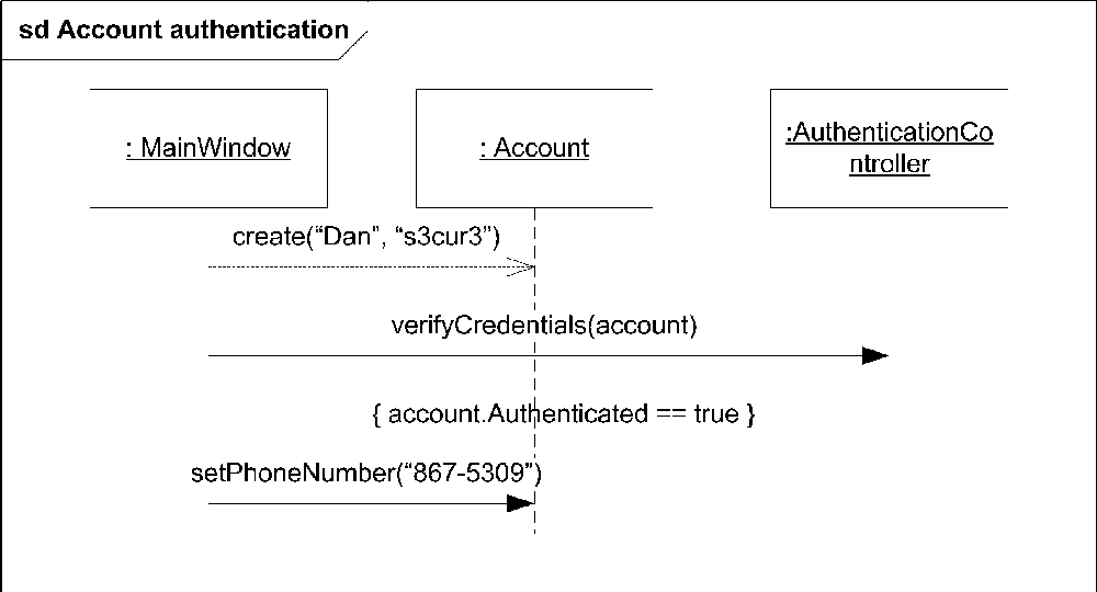
You show a boolean state invariant by simply placing the conditional inside curly braces ({}) on the lifeline of the object you want to check. The invariant will be evaluated after any messages that come above it on the diagram. Figure 10-13 shows a basic boolean invariant checking that an Account has been authenticated successfully.
You show an invariant as a UML state by simply drawing the state symbol (rectangle with rounded sides) over the appropriate part of the lifeline of the object you want to check. The actual information that is validated by the state can be expressed using the normal UML state diagram notation. Figure 10-14 shows the same Account authentication using a UML state.
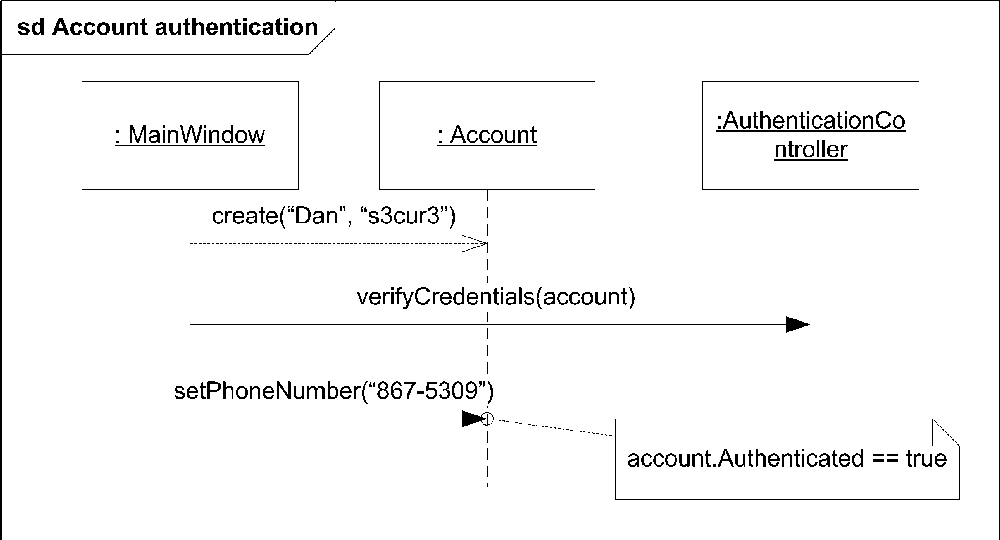
UML allows you to place the state invariant information inside a note and link it back to the lifeline, though this doesn’t tend to be as obvious to the reader as seeing a constraint directly on the lifeline in the proper sequence. Figure 10-15 shows a state invariant using a note.

Event Occurrences
Event occurrences are the smallest building blocks of interaction diagrams; they represent moments in time when something happens. Sending and receiving a message are the most common types of event occurrences, though technically they can be any action associated with an object. For example, if object1 sends a message to object2, there are two event occurrences, a message send and a message receive. UML carefully defines interaction fragments as a set of event occurrences where ordering is significant because they represent events over time.
Each type of interaction diagram notation (sequence, communication, etc.) has a way of expressing the time-sensitive nature of the event occurrences. In a sequence diagram the event occurrences are ordered along the lifelines and are read from top to bottom. Figure 10-16 shows a sequence diagram with three of the event occurrences labeled (as mentioned earlier, any action associated with an object is an event occurrence, but to keep the diagram from getting out of control only three are labeled in the figure).

Traces
UML defines a trace as a sequence of event occurrences. The term trace is used when discussing sets of event occurrences and how they may be combined. Interaction diagrams allow you to combine fragments in such a way that the event occurrences are interleaved. This combined set of event occurrences is considered a new trace.
Throughout this chapter we will refer to a sequence of event occurrences as event occurrences rather than as a trace to try and reduce the number of keywords.
Combined Fragments
Often there are times when a particular sequence of event occurrences has special constraints or properties. For example, you may have a critical region within your interaction where a set of method calls must execute atomically, or a loop that iterates over a collection. UML calls these smaller pieces interaction fragments.
Interaction fragments by themselves aren’t terribly interesting, however UML allows you to place them in a container called a combined fragment (it’s called a combined fragment even if you have only one interaction fragment in there). Once they are placed in such a container, UML allows you to specify additional detail for each fragment, or how several fragments relate to each other.
Each combined fragment is made up of an interaction operator and one or more interaction fragments, which are the interaction operands. An interaction operator specifies how the interaction operands should be interpreted. The various interaction operators are described in detail later in this chapter.
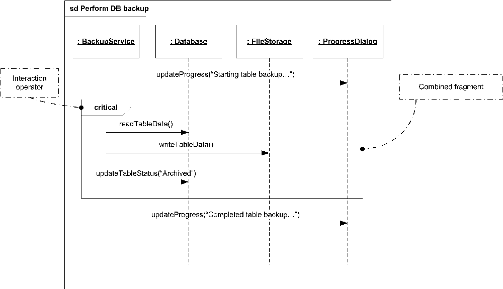
As you do with full interactions, you show a combined fragment as a rectangle, with the interaction operator in a pentagon in the upper left and the interaction operands inside the rectangle. Figure 10-17 shows a combined fragment representing a critical section of code. The code must be executed atomically because of the interaction operand critical. This and other interaction operators are described in "Interaction Operators.”
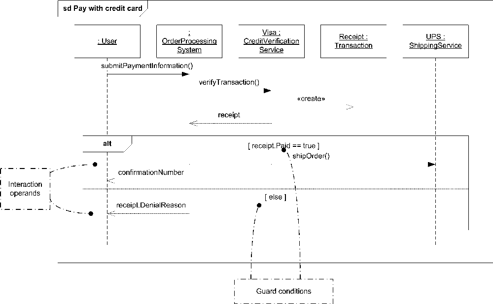
Depending on the interaction operator you choose for a combined fragment, you may need to specify multiple operands. You separate operands using a horizontal dashed line across the rectangle. Messages aren’t permitted to cross between interaction fragments. The order of the operands is significant for some of the operators, so always read a combined fragment from top to bottom. See Figure 10-18 for an example of multiple operands.
Guard Conditions
An interaction fragment may have a guard condition that states when the fragment is valid (can be executed); as in an “if-then” condition. The syntax for a guard condition is simply:
[ boolean_expression ]You show a guard condition directly above the first event occurrence in the relevant interaction fragment and on top of the associated lifeline. A guard condition can refer to any local data available to that lifeline, or to any global data available to the overall interaction; it can’t refer to the local data of some other lifeline. Figure 10-18 shows an example of an alternative interaction operator that models an if-else condition.
See the description for each interaction operator to see when guard conditions
are necessary and how they are used. If you don’t place a guard condition before an interaction fragment, it is interpreted as a guard condition that always evaluates to true.
Interaction Operators
Each interaction operator defined in the UML 2.0 specification is explained in detail in the following sections. Each operator has an associated number of operands and a keyword that is placed in the pentagon of a combined fragment.
Alternatives
Alternates are a choice of the behavior that executes based on guard conditions placed before each operand. The interaction operator is alt. You may include an else guard condition that executes the associated operand when the other conditions are false. Figure 10-18 shows this.
Option
Options are interaction fragments that executes only if the guard condition is true. The interaction operator is opt. Conceptually, options are similar to an alt operator with only one operand. Figure 10-19 shows an option operator.
Break
A break indicates that the associated interaction fragment operand should execute and then terminate the enclosing interaction. The interaction operator is break. A break is similar to the following code block:
if (guardCondition) { ... ; return; }
Figure 10-20 shows a break operator.

Parallel
Parallel indicates that the associated interaction fragments may be merged and executed in parallel. The interaction operator is par. UML specifies that the actual interleaving of the event occurrences of the operands must be done in such a way that the ordering in the original operand is maintained. For example, if the first operand consists of:
    Step1
    Step2
    Step3
and the second consists of:
    StepA
    StepB
    StepC
they can be merged into:
    Step1
    StepA
    StepB
    Step2
    StepC
    Step3
but not into:
Step1
StepB
Step2
StepA
Step3
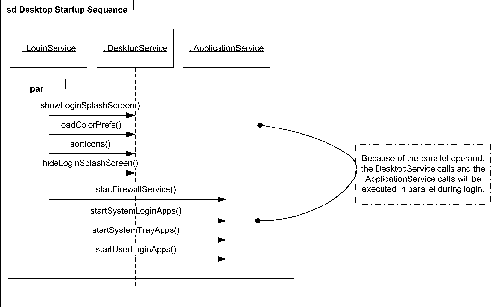
StepCbecause stepA and stepB would be executed out of order. Figure 10-21 shows an example of the parallel operator to model a desktop login sequence.
If you need to convey that a particular event occurrence must come before another event occurrence, UML has an explicit notation called a general
ordering
. You can show a general ordering anywhere in an interaction diagram, but it must connect two event occurrences. You simply draw a dotted line between the two event occurrences, with a solid arrow in the middle of the line pointing toward the occurrence that must happen second. For example, if you don’t want the login splash screen in Figure 10-21 to be hidden until all the applications are started, you can indicate that the startUserLoginApps() call must occur before the hideLoginSplashScreen() call. Figure 10-22 shows how to use a general ordering to indicate that the application startup must complete first.

Weak sequencing
Weak sequencing indicates that the event occurrences in each operand can be interleaved according to the following rules:
The ordering of the event occurrences within each operand is maintained. For example, if the first operand has
<step1, step2, step3>and the second operand is<stepA, stepB, stepC>, they may be interleaved to<step1, stepA, step2, stepB, step3, stepC>because the order is maintained, but not to<step1, step3, stepA, step2, stepB, stepC>because the ordering of the event occurrences in the first operand is changed.If event occurrences in different operands occur on different lifelines, they can be interleaved in any order.
If event occurrences in different operands occur on the same lifeline, they can be interleaved only in such a way that the event occurrences of the first operand execute before the occurrences of the second operand.
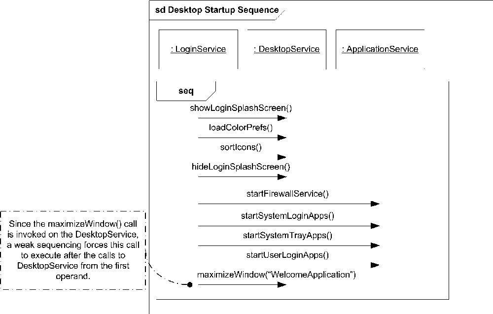
The interaction operator is seq. For Figure 10-22, a weak sequencing
wouldn’t change the way the calls are interleaved because the first operand has calls only to DesktopService and the second operand has calls only to the ApplicationService. However, if the sequence is changed so that the second operand includes a call to the DesktopService, it isn’t allowed to execute until all the calls to DesktopService in the first operand are complete (Rule #3). Figure 10-23 shows this new sequence diagram.
Strict sequencing
Strict sequencing indicates that the ordering of the event occurrences is significant across lifelines, not just within the same lifeline (as with weak sequencing). The operands of a strict sequence must be executed in order, from top to bottom. The interaction operator is strict.
Negative
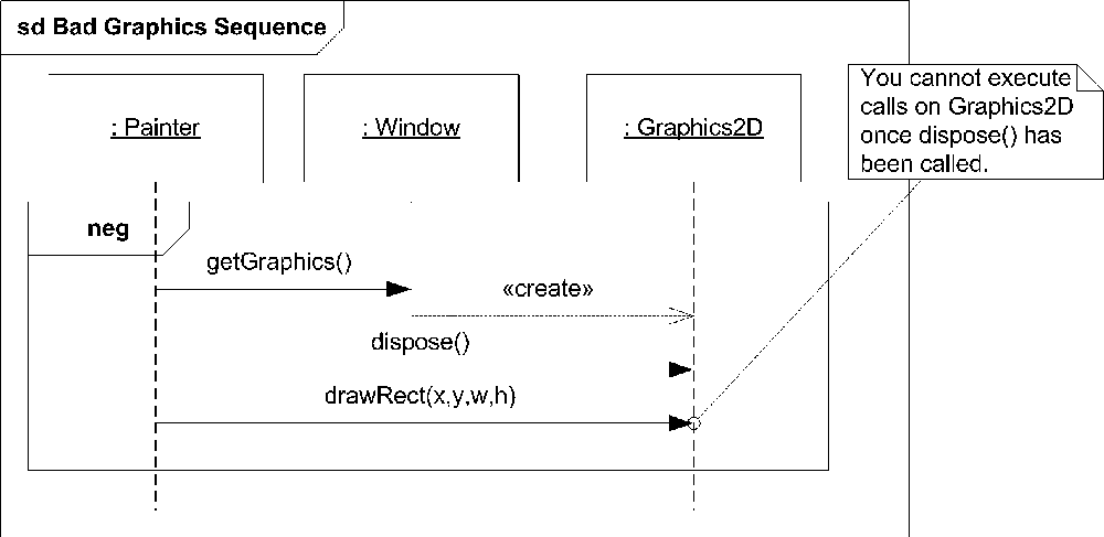
Negative indicates a set of event occurrences that are considered invalid, meaning the interaction can never execute this particular path. The interaction operator is neg. This particular operator is rarely used but can convey that the particular sequence isn’t permitted. Figure 10-24 shows an example of an invalid call to a Graphics2D object. In this diagram, a UML note indicates to the reader why the particular sequence is invalid.
Critical region
A critical region indicates that the given event occurrences must be treated as an atomic block. The interaction operator is critical. Critical regions are typically used inside other interaction fragments (such as a parallel fragment) to ensure that a group of event occurrences can’t be separated.
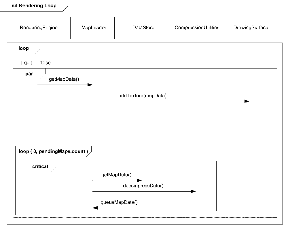
Figure 10-25 shows an example rendering engine loop that checks to see if map data is available for drawing. Because loading map data may be an expensive operation, we’ll allow the loading to be executed in parallel with the rendering. However, compressed map data can’t be rendered, so the loading and decompression must occur as an atomic operation.
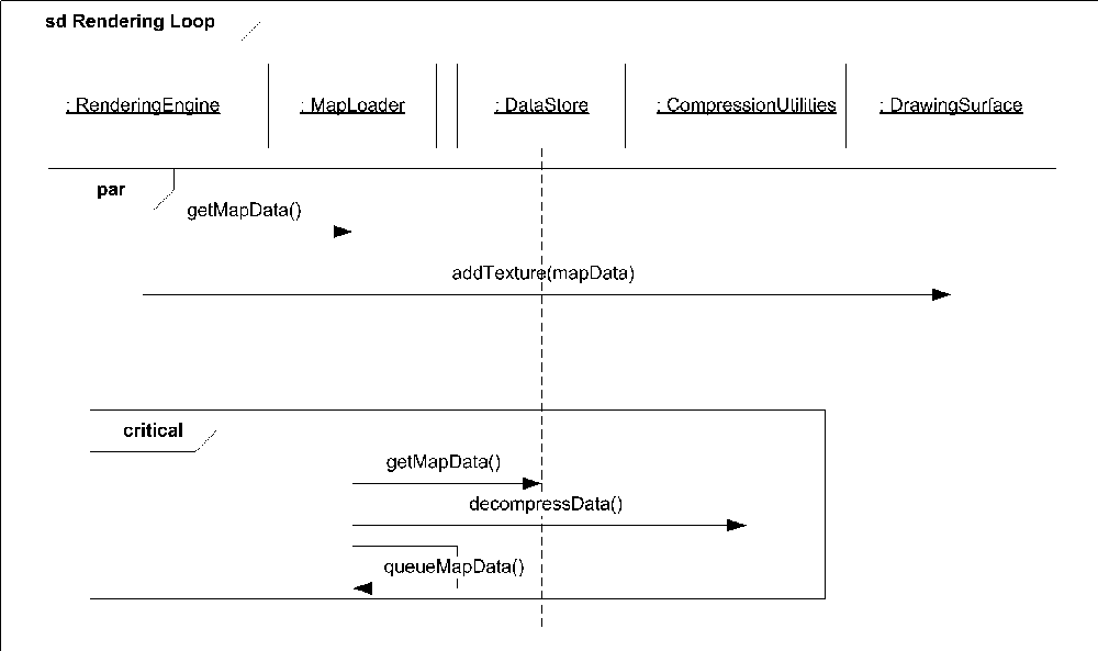
Because Figure 10-25 needs to represent a continuously running process (the rendering loop), it’s better to model the looping conditions with the loop operator shown later in this chapter (see "Loop“).
Ignore/consider
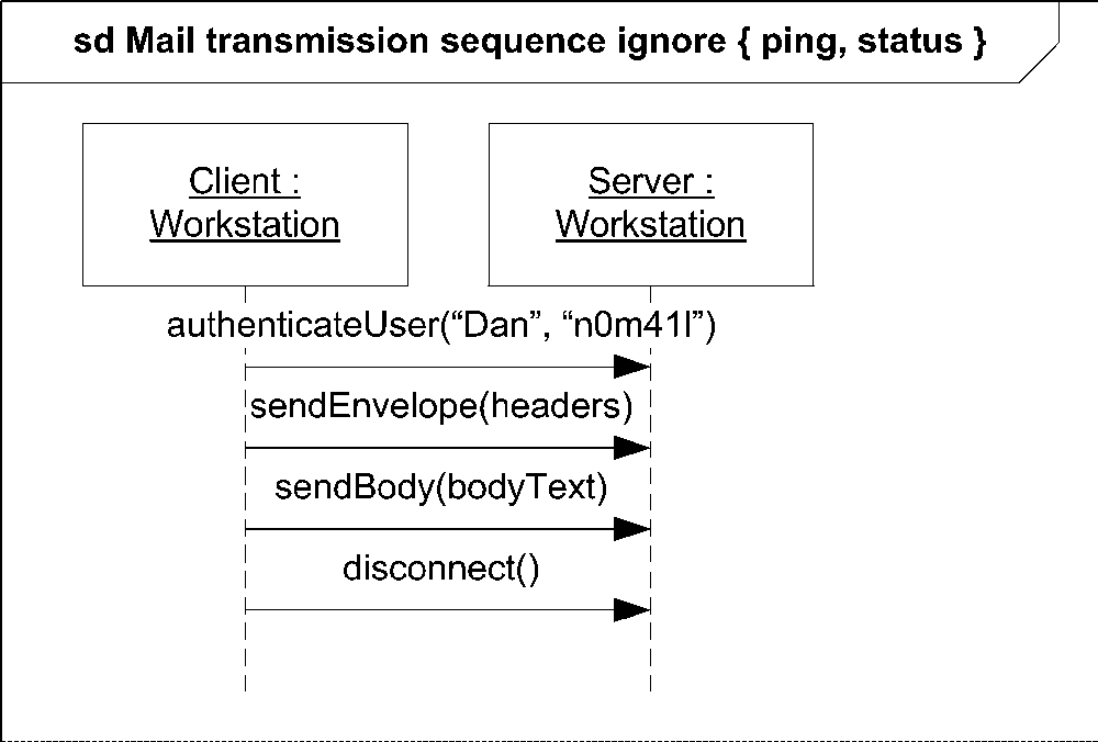
Ignore specifies a set of messages that aren’t shown on the interaction fragment and can be safely ignored. This typically implies that the ignored messages are irrelevant for the purpose of the diagram; however, they may still occur during actual execution. The interaction operator is ignore, and the syntax is:
ignore { messagename, messagename, ... }
Figure 10-26 shows an example of the ignore operator that models a simple mail transmission protocol. In this sequence, ping and status messages are explicitly ignored. This means they can occur anywhere during this sequence and should be handled by the system, but are irrelevant to the flow of execution we’re trying to model.
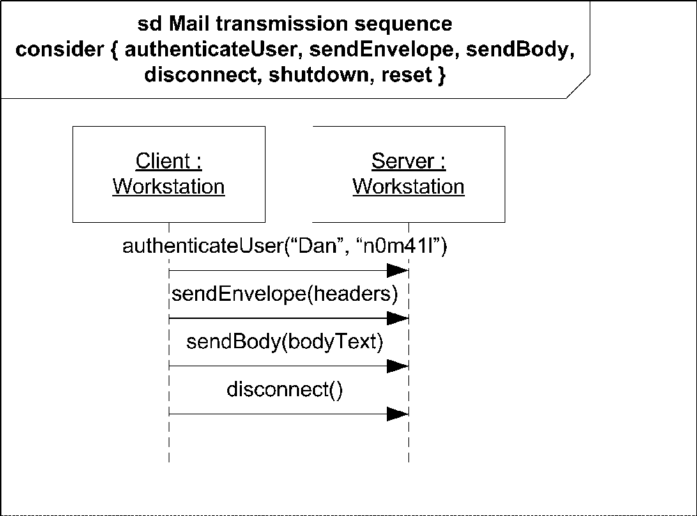
Consider specifies a set of messages that are explicitly relevant to the diagram, so you can safely ignore any other message. The interaction operator is consider, and the syntax is:
consider { messagename, messagename, ... }
Figure 10-27 shows the same mail transmission sequence as that shown in Figure 10-26 but explicitly considers authenticateUser, sendEnvelope, sendBody, disconnect, shutdown, and reset. Because shutdown and reset aren’t shown on the sequence diagram, it’s invalid for either message to occur during execution.
Assertion
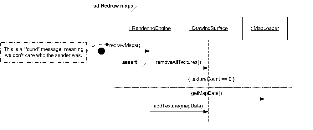
An assertion indicates that the contained event occurrences are the only valid execution path. The interaction operator is assert. Assertions are typically combined with some kind of state invariant to enforce a state of a system.
Figure 10-28 shows a sequence diagram in which the user requests that maps be redrawn. The RenderingEngine instructs the DrawingSurface to remove all the existing textures, and the assertion guarantees there are no textures left.
Loop
A loop indicates that the contained event occurrences are to be executed some number of times. The interaction operator is loop. The notation for a loop includes a minimum and maximum number of times a loop should execute. You
may also use a guard condition that is evaluated each time through the loop to terminate execution. The syntax for the operator is:
loop (min,max)
where both min and max are optional. If max is excluded, max equals min. max may be an asterisk (*) to indicate an infinite loop (or at least while the guard condition evaluates to true). If both min and max are excluded, min equals 0, and max equals infinity; in this case you likely want to have a guard condition to prevent the loop from executing indefinitely.
Figure 10-29 shows the rendering loop modeled in Figure 10-25. In this sequence diagram, the looping is explicitly shown with a guard condition that will terminate the loop when the user has set the quit flag to be true. There is also an inner loop that instructs the MapLoader to execute while there are maps to load.
Interaction Occurrences
An interaction occurrence is shorthand for copying one interaction into another, larger interaction. For example, you can create an interaction that simply shows user authentication and then reference it (create an interaction occurrence) in larger, more complete interaction diagrams.
The syntax for an interaction occurrence is a combined fragment rectangle with the interaction operator ref. Place the name of the referenced interaction in the rectangle. UML allows parameters to be passed to referenced interactions using the following syntax:
attribute_name=collaboration_occurrence.interaction_name(arguments) :return_value
where:
-
attribute_name Is an optional part of the syntax that specifies what attribute the return value should be applied to. The attribute must be an attribute of a lifeline in the larger interaction.
-
collaboration_occurrence Is an optional scoping of the referenced interaction if it is part of a larger collaboration.
-
interaction_name Is the name of the interaction to copy.
-
arguments Is a comma-separated list of arguments to pass to the referenced interaction. The arguments may be values or parameter names. If only argument values are used, arguments are matched against the interaction parameters, in order. If you want to skip an argument, you place a dash (
-) where the argument would be. Skipped arguments have unknown values. You may explicitly identify a parameter name by following its text name with a colon (:) and then the value. If you use parameter names, you may omit arguments not relevant to the interaction. As with a dash, skipped arguments have unknown values.You may prefix an argument with the keyword
outorinoutto indicate that the argument is used to return a value. If the argument is used as anoutargument, a value after the colon in the argument specification is interpreted to be the return value.-
return_value Is an optional part of the reference that, if present, indicates the value returned by the copied interaction.
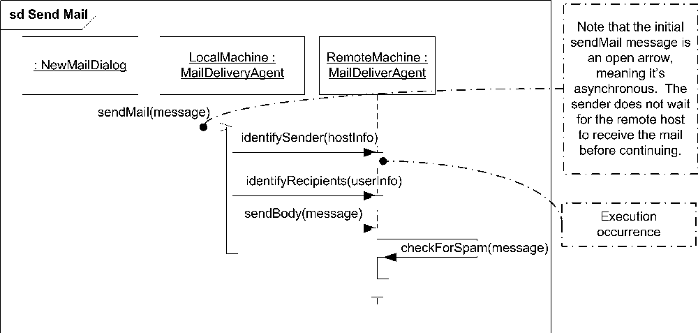
Figure 10-30 shows a simple mail transmission sequence diagram that uses an interaction occurrence to refer to another sequence diagram that illustrates user authentication. In this example, the return value from the interaction occurrence is ignored, so it isn’t assigned to any variable.

Decomposition
A participant in an interaction diagram may be a complex element in and of itself. UML allows you to link interaction diagrams by creating a part decomposition
reference from a participant to a separate diagram. For example, you may have a Purchase Item interaction diagram that has a participant execute a credit card authorization. The actual details of the authorization process are probably not of interest to the readers of your Purchase Item diagram; however, they are vitally important to the developers responsible for the authorization subsystem. To help reduce clutter on your diagrams, you can create a separate diagram showing how the authorization subsystem validates credit cards and place a decomposition reference to that on the Purchase Item diagram.
To create a part decomposition reference, simply place ref interaction_diagram_name
after the instance name in the head of your lifeline. Figure 10-31 shows how the Purchase Item and authorization diagrams can be modeled.
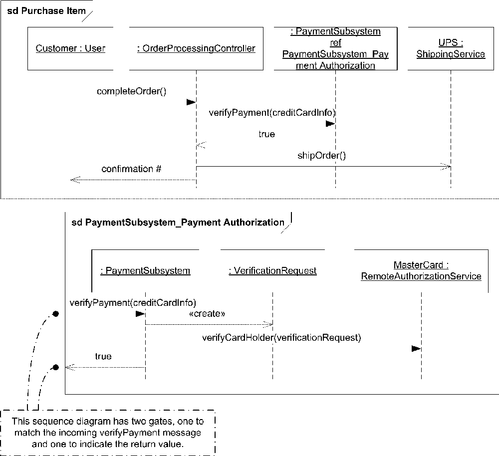
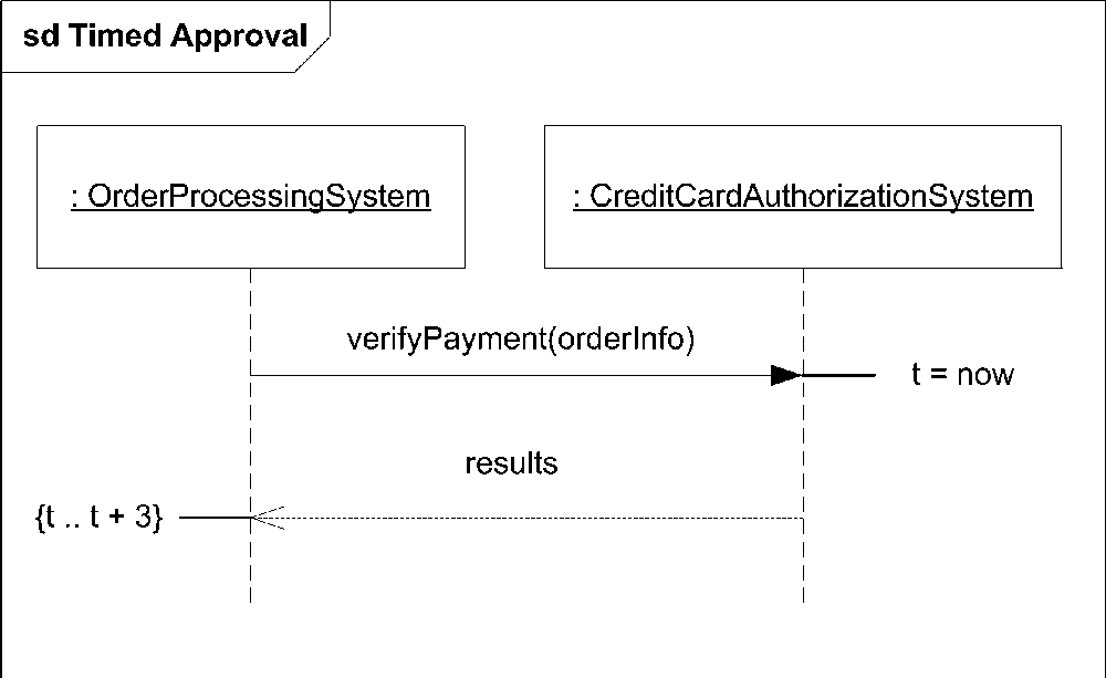
Messages that come into or out of the decomposed lifeline are treated as gates that must be matched by corresponding gates on the decomposition. A gate represents a point where a message crosses the boundary between the immediate interaction fragment and the outside environment. A gate has no symbol of its own; you simply show a message pointing to the edge of the frame of an interaction fragment. The entire purpose of a gate is to show an object that sent a message connecting to the object that received the message.
By default, a gate’s name is based on the direction (in or out) and the message in question. For example, a gate showing a message named verifyPayment leaving an interaction fragment is named out_verifyPayment. However, you may explicitly name gates if that adds readability to your diagram.
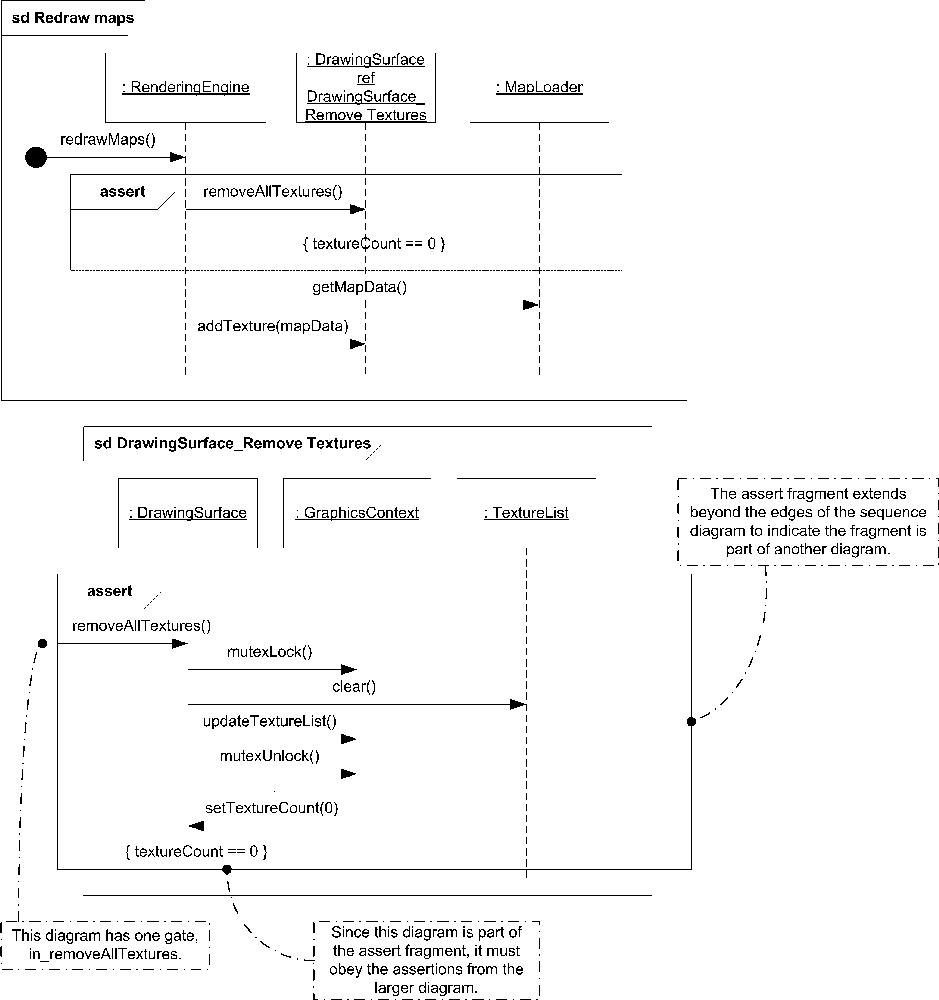
If the messages shown in the decomposition are part of a combined fragment in the larger interaction diagram, the decomposition must inherit the same interaction operand. UML defines this as extra-global
. For example, if the larger interaction is part of an assert interaction operand, and the state invariant is declared on the lifeline you want to decompose, that state invariant (and its assertion) must apply to your decomposition. You can show extra-global combined fragments by drawing the combined fragment on your decomposition, but making the combined fragment rectangle larger than your decomposition rectangle. Figure 10-32 shows an assertion decomposition of the rendering engine example used earlier in this chapter.
The UML specification recommends that you name your decomposition diagrams using an abbreviation for the object being decomposed, followed by an underscore (_), followed by the name of the interaction. For example, if you are modeling a credit card authorization system and want to show how a card is validated, you can name your decomposition CCAS_Validation.
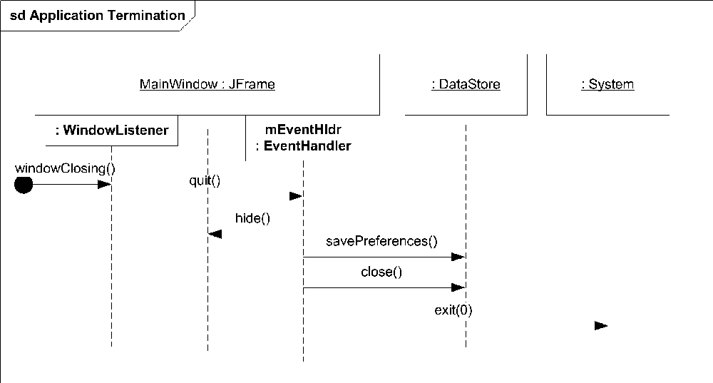
You can also show decompositions inline by showing parts of the decomposed element attached as smaller rectangles to the bottom of the head of the lifeline. Each part gets its own lifeline. This can be useful to show inner classes receiving or sending messages. For example, it is common practice in Java to declare an inner anonymous class to handle GUI events. If you felt this was relevant to your interaction you can show this level of detail on the main interaction diagram. However, inline notation is relatively uncommon because decompositions are typically used to show a complex, subinteraction that would clutter the top-level diagram.
Figure 10-33 shows an example inline part decomposition where MainWindow has two inner classes: an anonymous WindowListener and an instance of an EventHandler named mEventHldr.
Continuations
Typically used with interaction references, continuations allow you to define different branches of an alternative interaction outside of the alternative itself. Continuations are conceptually similar to named blocks of functionality.
The notation for continuations can be particularly confusing. You show a continuation using the symbol for states, a rectangle with rounded sides; however, the position of the rectangle changes the meaning of the diagram. You place a continuation at the beginning of an interaction to define the behavior for that continuation. You use a continuation by showing the rectangle at the end of an interaction. Finally, continuations with the same name must cover the same lifelines (and only those lifelines).
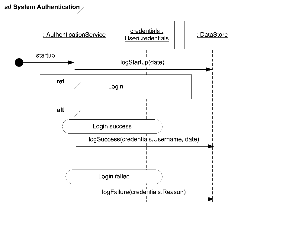
Figure 10-34 shows the first of three sequence diagrams demonstrating a continuation; this one displays the details of a Login sequence. After the password is retrieved from the database, an alternative interaction is entered. If the passwords match, various flags are set on the UserCredentials. After setting the flags, there is a continuation named Login success, in which users of this sequence diagram can plug in their own functionality. If the passwords don’t match, the else part of the alternative interaction executes, which leads to the Login failed continuation. Notice the continuation symbols are at the end of each interaction operand, indicating this diagram uses an externally defined continuation.

Figure 10-35 shows the second diagram, a sequence diagram that makes use of the Login sequence and defines continuations for Login success and Login failed. If the correct password was entered, the Login success continuation is executed; otherwise, the Login failed continuation is run. Notice in this diagram that the continuation symbols are at the top of the interaction, indicating that this diagram defines the behavior to execute.
Taken together, these two diagrams are equivalent to Figure 10-36.
Sequence Timing
UML provides a notation to capture a specific time associated with an event occurrence. You simply place a small horizontal line next to an event occurrence to capture the time of the occurrence, or place a timing constraint on it. Typically, you use a variable to capture a specific instance in time and then represent constraints as offsets from that time. Constraints are expressed like state invariants and placed next to the event occurrence.
For example, if you want to express that a credit card authorization system must return approval or denial within three seconds of placing the request, you can place time constraints on the event occurrence, as shown in Figure 10-37.
Alternate Interaction Notations
UML provides several notations for capturing interactions. The first part of this chapter used the sequence diagram notation. The remainder of this chapter describes the other notations available and when they may be more appropriate than sequence notation.

Communication Diagrams
Communication diagrams allow you to focus on the elements involved in interactions rather than the detailed sequencing and flow control allowed in sequence diagrams. Most UML tools can automatically convert from a sequence diagram to a communication diagram; however, because communication diagrams aren’t as expressive,.some information may be lost.
When you’re modeling with communication diagrams, objects are represented by a rectangle, and connections between objects are shown as a solid line. Each message has a sequence number and a small arrow indicating the direction of the message along a given connection. Communication diagrams can’t show message overtaking (see Figure 10-6 earlier in the chapter) or interaction fragments.
Figure 10-38 shows a simple sequence diagram and the equivalent communication diagram.
The syntax for a message name is:
sequence_number:name [recurrence_or_guard]

where:
-
sequence_number Is the index of the message with 1 being the index of the first message in the diagram. You show nested message calls by appending the original message number with a decimal and then starting a new sequence. For example, if the
listen()call in Figure 10-38 makes a nested call tostartTimer(), numberstartTimer()as3.1.You can show concurrent messages using letters in the sequencing. For example, if the
ListentingPortinstance can support multiple parallel listening calls, theMainWindowinstance can call thelisten()call twice, labeling the first call as3aand the second as3b. Both calls can execute concurrently.-
name Is the name of the message being sent (or method call).
-
recurrence_or_guard Is an optional part of the syntax that allows you to specify a boolean condition that must be
truefor the message to occur, or a range of integer values for looping. Guard conditions are represented as normal boolean expressions; for example,[password.Valid == true]. UML doesn’t provide a syntax for specifying looping constraints but does say they must begin with an asterisk (*). For example, you can represent a loop that executes from 0 to 10 as*[i = 0 .. 10].
Interaction Overview Diagrams
Interaction overview diagrams represent interactions using a simplification of the activity diagram notation (see Chapter 9). Interaction overview diagrams can help you visualize the overall flow of control through a diagram; however, they don’t show detailed message information.
You can embed interactions or interaction occurrences inside an interaction overview diagram if it is helpful to see message details for a subset of the overall interaction.
Several sequence diagram concepts are supported in interaction overview diagrams :
Show combined fragments using a decision node and merge node.
Show parallel interactions by using a fork node and join node.
Show loops as cycles in the activity diagram.
Show names of the lifelines involved in an interaction using the keyword
lifelinesafter the name of the interaction overview diagram, followed by a comma-delimited list of each lifeline’s name (including any colon separators that may or may not be part of the name).
Figure 10-39 is an interaction overview diagram showing a subset of the interaction shown in Figure 10-36.
Timing Diagrams
Timing diagrams are a special representation of interactions that focus on the specific timings of messages sent between objects. You can use timing diagrams to show detailed time constraints on messages or to show when changes occur within lifelines with respect to time. Timing diagrams are most often used with real-time or embedded systems.
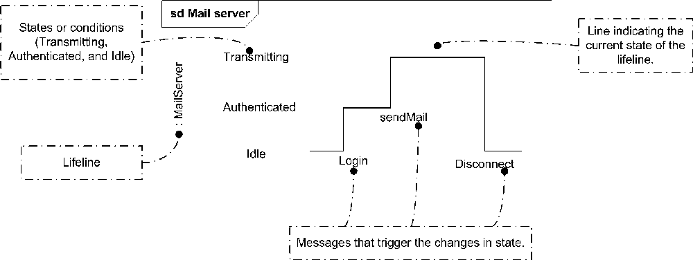
Unlike sequence diagrams, timing diagrams are read left to right rather than top to bottom. You show a lifeline name along the left edge of the diagram. The various states of the lifeline are then listed, followed by a graphical representation of the transitions between these states. Figure 10-40 shows an example of a timing diagram in which the MailServer object progresses through several states.
In Figure 10-40, the MailServer starts in the Idle state until the Login event occurs. The Login event causes the MailServer to transition to Authenticated. When the sendMail event occurs, the MailServer transitions to Transmitting and remains there until disconnected.

When reading the diagram left to right, you can use the length of the timeline to indicate how long the object remains in a particular state. To associate time measurements, you show tick marks along the bottom part of the frame, as shown in Figure 10-41.
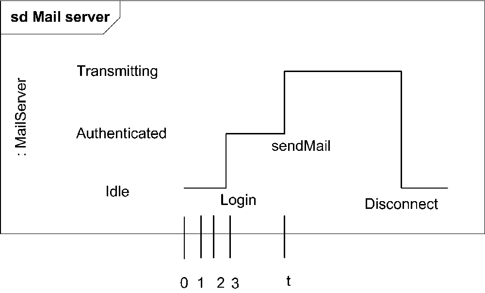
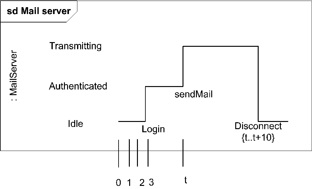
Figure 10-41 shows that the Login event is received three time units after the start of the sequence. To show relative times
, you can mark a specific instance in time using a variable name. Figure 10-41 marks the time the sendMail event is received as time t. You can use relative time marks in constraints to indicate that a message must be received within a specified amount of time. Figure 10-42 shows the Disconnect message must be received within 10 time units of the sendMail event.
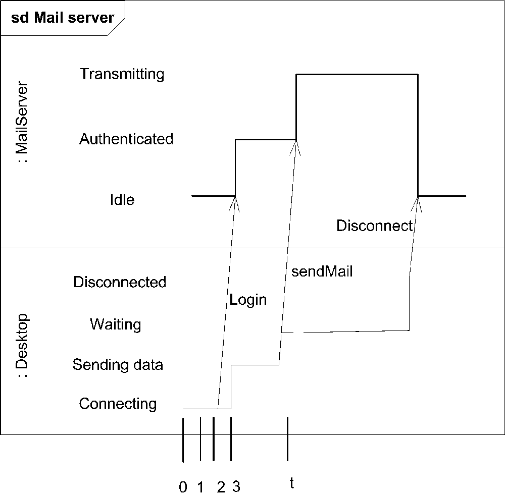
You can show multiple objects involved in a timing diagram by stacking the lifelines. You show messages between objects using an arrow from one timeline to another. The start and end of the arrow correspond to when the message is sent and received. This notation shows the triggers that cause a transition; however it
very quickly becomes unreadable if a lot of messages are exchanged. Figure 10-43 shows the MailServer talking with a client, Desktop.
UML provides a variation on the timeline notation that simplifies diagrams by showing state names between two horizontal lines that cross when the state changes. This notation makes it much easier to show multiple objects along a single timeline, but it doesn’t show the messages that trigger transitions. Figure 10-44 shows the MailServer and Client lifelines progressing through state transitions.
