Chapter 11. Tagged Values, Stereotypes, and UML Profiles
The UML described in the previous chapters allows you to understand any UML model. You can understand the analysis of a billing system, the implementation model of a CORBA system, a gaming system in C++, or an EJB e-commerce system.
Practitioners rarely work on such diverse systems at one time, however, and no UML model will represent more than one type of application. More commonly, a practitioner (that’s you) works with colleagues on one system or a series of closely related systems exclusively. For example, you might design a series of gaming systems, or a series of .Net systems. And, as you might expect, the specific concerns of a gaming system differ profoundly from those of a .Net system.
UML allows toolmakers to create a dialect called a profile, tailored to a specific niche. Within a niche, a stereotype gives specific roles to elements, and records additional context-specific information in tagged values. Profiles also include constraints that ensure integrity of use.
A practitioner familiar with a profile will immediately grasp the meaning of a model developed using that profile, because of the unique stereotypes. Moreover, the model contains deeper meaning, because of the tagged values, and the model has a higher degree of integrity, because of the constraints. This gives a distinct advantage to practitioners and tools working in the niche. People and tools unfamiliar with the profile will process it only at a formal level, without any special understanding.
Profiles are the standard mechanism to extend UML. The profile mechanism exists within UML so models applying a profile are fully UML compatible. This contrasts sharply with implementors’ extensions in loosely specified languages such as C++, in which the specification allows inline assembler and #pragma statements, making it virtually impossible to port C++ programs between processors or between different compilers. A UML model applying a profile is UML, and any UML tool can process it.
Although a plethora of dialects can fragment the universality of UML, a dialect makes UML more useful. And isn’t that what it’s all about?
Modeling and UML in Context
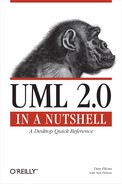
Throughout the evolution of modeling, practitioners, implementors, academics, and other interested parties have found new and innovative ways to model, and new disciplines to model. It soon became apparent that the generality of the canonical UML was not concise enough for practitioners working full time in a particular language, technology, or platform, such as ANSII C++, Struts, or .Net. Moreover, practitioners in similar disciplines, such as process engineering, with different fundamental structures and constraints found UML interesting but not quite appropriate. They can better benefit from a UML-like language other than UML itself. Figure 11-1 illustrates this situation, where the Meta-Object Facility (MOF), explained more fully later in the chapter, comprises all UML models as well as UML-like models.
The authors of UML could have specialized UML for common programming languages (such as C++, C#, Java, and Visual Basic) and platforms (such as embedded systems, real-time operating systems (RTOS), EJB, and .NET). This would have created an unworkable modeling language, as each programming language or dialect polluted the specification with conflicting definitions. It would still require an extension mechanism because some “uncommon” language (such as Smalltalk) or new platform/technique or version (like EJB 3.0) would always be missing from the formal specification.
On the other hand, the authors could have stretched UML to greater abstraction to embrace uses other than software development, such as business modeling, modeling the process of software development itself, or modeling systems engineering. This would have made everything even more abstract. Because designers work in only one specific domain, abstraction impedes concise expression, moving the models further from their domains.
Instead of burdening UML with complexity, or overwhelming it with abstraction, UML’s authors factored out everything specific to domains and platforms. They created the profile extension mechanism to address the specific needs of specific application domains. CORBA models, for example, would be concise and precise, but would not influence a .Net model.
Although UML cousins, such as the Object Management Group’s Software Process Engineering Metamodel (SPEM) and SysML.org’s Systems Modeling Language (SysML), borrow much structure from UML, they also discard parts that bring no value to their disciplines. SPEM, best known as the basis for the Rational Unified Process (RUP), describes the process of software development in terms of process roles, work products, and activities. Between a software application and the process of software development, the fundamental structure and relationships between the parts change. Although much is similar in the statechart, class, sequence, package, use case, and activity diagrams, for example, there is no implementation or component diagram, or interface. A profile specializing a few elements works, but it must exclude or constrain many basic concepts. MOF factors out the structure of UML itself for reuse in other disciplines. Using MOF, SPEM and SysML become metamodels at the same level as UML. UML remained close to the disciplines of general software development, and business and data modeling. In other disciplines, a new metamodel can be created from adding, dropping, and reorganizing UML packages to allow for a concise modeling of the discipline.
More formally, as seen in Figure 11-2, UML builds on its core infrastructure, MOF. MOF can be used by other modeling languages for other uses. The core UML can be used as is for building models directly, or it can be constrained by one or more profiles.
Each level is a level of abstraction. The levels are named M0, M1, M2, and M3, as they become more abstract. M0 is the concrete system—the code. M1 is the model of the system (of which M0 is just one realization)—the model where designers work. M2 is the language used to describe the model, in this case UML and, optionally, the profiles. M3, MOF, is the language used to describe UML and any similar modeling languages. MOF is far beyond the scope of this book. Suffice it to say, though, that MOF provides a formal infrastructure to UML, which explains why stereotypes resemble classes and components, and why tagged values resemble enumerations and attributes.
The M1 model, specifying your application, may have profiles associated with it. The architect determines the profiles to use according to the platform, language, and tools available. Deciding the profile effectively freezes the M2 layer. As an application modeler, you model classes, attributes, states, and all the other UML elements. You don’t define new stereotypes or tagged values. You assign existing stereotypes. You fill in the values appropriate to the tags.

Unless you are also building your own tooling for code generation, reporting, and/or tracking, you will employ the profile(s) as is. As a «singleton», for example, the class needs certain supplementary information. The code generator needs the same questions answered for every «singleton»; no more, no fewer. It makes no sense to have a {multithread-safe=true} tagged value for one «singleton» if the code generator doesn’t recognize it. If it does recognize it, every «singleton» should have it. It really depends on the tool.
Some teams do build their own tooling. Even then, only the toolsmith works in the M2 layer, and the modelers work in the M1 layer. Changes in the M2 layer must be conservative because one new tagged value in a stereotype can imply revisiting tens or hundreds of elements in the model. Changes in the M2 layer literally change the fundamental meaning of an M1 model. You’ve been warned.
Stereotypes
Stereotypes modify the intent of the elements to which they apply. They allow the differentiation of roles of an element within the model. For example, you can quickly differentiate classes stereotyped as Controller as having a different role in the system than those stereotyped as View.
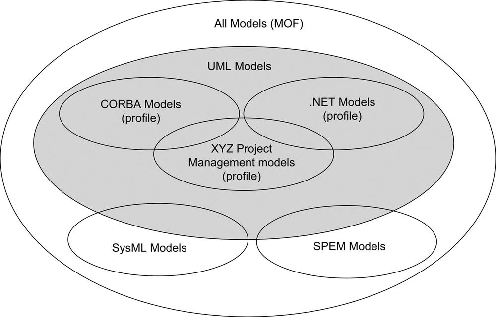
Visually, UML allows graphical and textual representation of a stereotype. Graphics and text can be combined in various ways for node-type elements, as shown in Figure 11-3. The four elements that you see going across the top of the figure all represent the same combination of Form and key stereotypes but in different ways. Edge-type elements have only a textual representation, and thus you see «depends» on the dependency between Billing and Inventory.
When displayed as text, a stereotype is enclosed in guillemots («»), as in «MyStereotype». Because the guillemots require an extended character set to display correctly, you may also use double angle brackets to show a stereotype in 7-bit ASCII, as in <<MyStereotype>>.
Graphical icons are neither defined nor standardized by UML. You can expect toolmakers to extend the graphics differently, including coloring or shading, at their discretion. Avoid graphical symbols for interchange of models between different tools. However, within the controlled environment of a compatible set of tools, specialized graphics and/or colors will likely have more visual impact.
Tip
While stereotypes have been around since the initial beta versions of UML, UML 2.0 has introduced significant changes to the 1.x versions:
Elements may have zero, one, or more than one stereotype. The use and usefulness of stereotypes have become more and more evident. More toolmakers have incorporated them into their products. Modelers found it impossible to use otherwise complimentary tools because an element can have only one stereotype.
Stereotypes may be nested. A specialized stereotype can build on the structure of a general stereotype. In the example provided later in this chapter, the
EJBPrimaryKeystereotype extends theEJBCmpFieldstereotype, because all primary keys are ordinary fields as well.Tagged values are related through a stereotype rather than directly to the element. This avoids the possibility of name clashes with the introduction of multiple stereotypes per element.
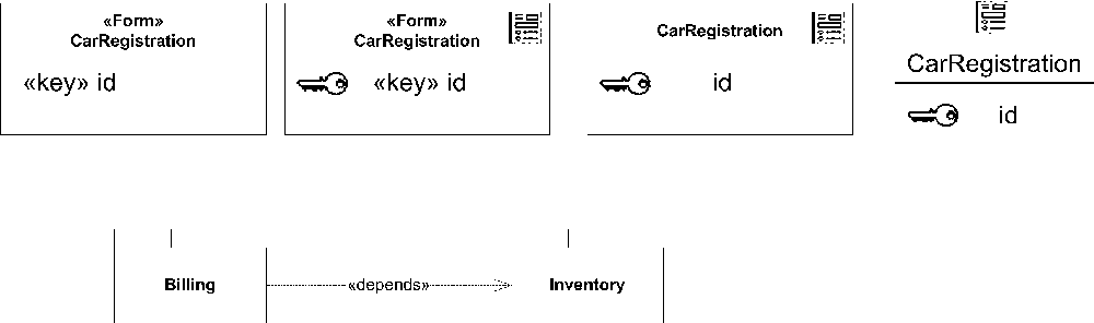
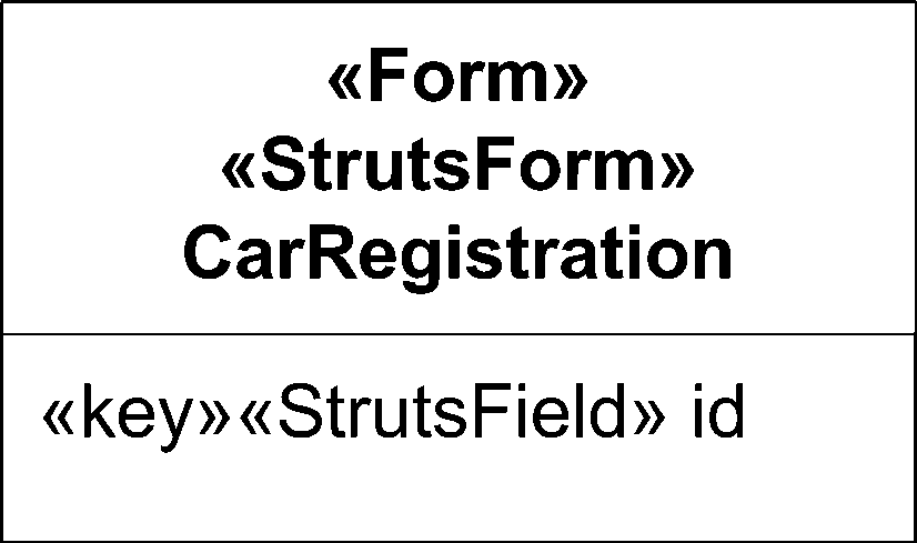
You can tag an item in a UML model with more than one stereotype. Figure 11-4 shows multiple stereotypes as a list, with each stereotype enclosed in «guillemots».
Tagged Values
Having established an element’s role within a system with a stereotype, the element likely needs information not available from the core UML, to fulfill its role. The stereotype defines a number of tagged values. Each tagged value is typed with a datatype—number, string, boolean, or user-defined enumeration. The upcoming section “UML Profiles” shows one way in which you might record, or define, the tagged values that you wish to include in a stereotype.
When you show them in a diagram, place the tagged values in a note element that is connected to the declaring element with a dashed line. Figure 11-5 shows the case of multiple stereotypes on one element. To keep the stereotypes and the corresponding tagged values clear, each stereotype is mentioned, and the tagged are values listed separately.

At first, you may confuse tagged values with attributes, but they exist at a different level of abstraction. Attributes, defined in the design model (M1), exist in the runtime system (M0). Tagged values, defined in the profile (M2), exist only in the design model (M1). The tagged values may provide hints to help the generation of code, either by human or machine. A tagged value of {optimize=space} will probably affect the code ultimately, although the actual value itself never appears in the code.
Constraints
Stereotypes give roles to elements. Tagged values provide role-specific information enriching the element in its role. While atomically the element knows its role and has all the information to fulfill it, the element must still interact with its neighbors. The element and their roles must be in harmony with the architectural vision. The element must also be internally consistent. Constraints (see "Constraints" in Chapter 2) provide the mechanism to specify rules for correct usage of the stereotyped elements.
UML Profiles
UML profiles combine the concepts of stereotypes, tagged values, and constraints to provide a coherent and concise dialect of UML for a specific family of applications. To make much use of a profile, some tooling must be provided. The application model drives code or application generation, so you have little or no control over the stereotypes, tagged values, or constraints comprising the profile. This section discusses the use of existing profiles (as opposed to defining your own).
Figure 11-6 depicts a partial UML profile defining a stereotype with its associated tagged values and a couple of constraints, as you might receive in a vendor’s documentation. The profile extends classes with a stereotyped class, «EJBEntityBean». It extends attributes with two stereotyped attributes: «EJBPrimaryKey» and «EJBCmpField». It declares the respective tagged values for the stereotyped classes and attributes, and it declares the enumeration, TransactionIsolationLevel, to define the allowable values for the TransactionAttribute tagged value. The profile also adds the constraints that «EJBEntityBean» classes must have attributes of type «EJBCmpField» and «EJBPrimaryKey». Furthermore, attributes having these stereotypes can exist only in an «EJBEntityBean» class. From your point of view, the profile, along with its constituent stereotypes and tagged values, is read-only because it tells what the third-party tool expects in order to do its job.
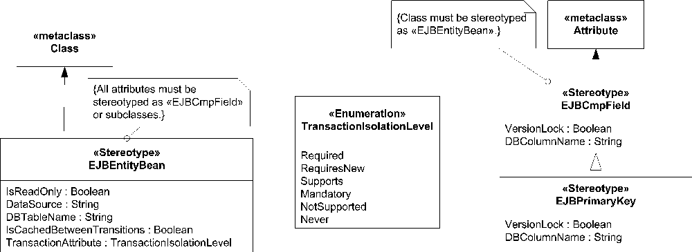
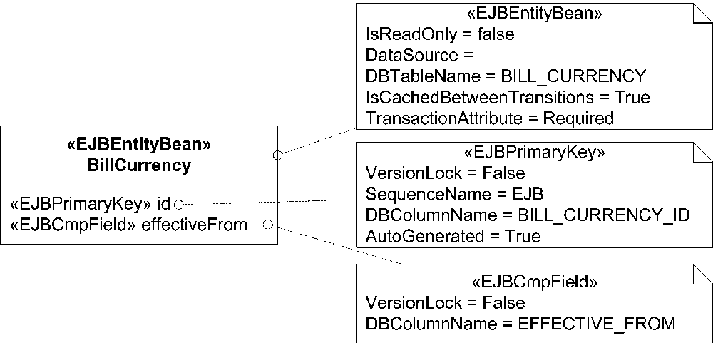
Figure 11-7 shows a portion of a model using the profile declared in Figure 11-6. Figure 11-8 indicates how the tagged value structures in the model relate back to the profile declaration. The notes containing the tagged values make the notation bulky if you need to show a set of tagged values for every class, attribute, operation, and relationship.
When aiming to expose the structure and relationships of a system, class diagrams rarely show tagged values. Referring again to Figure 11-7, one tiny class having two attributes becomes a constellation of four diagram elements. A modest class diagram of 10 classes can easily require 100 extra notes to show the tagged values, hopelessly confusing the diagram and destroying its impact. Instead, modelers often maintain the tagged values invisibly in the model, where tools can extract them as needed.

The UML from the profile and the model is shown in Figure 11-8. This illustrates the relationships between the declarations of the profile and a conforming model. The stereotypes in the profile extend the concept of an element. In this case, the stereotype «EJBEntityBean» extends ordinary classes, as shown (1) by the implication of the same element type (metaclass), Class. In the models applying this profile, only classes may have that stereotype, as shown by the relationship (2). Having established that the BillCurrency is an «EJBEntityBean», it now has all the «EJBEntityBean» tagged values, as shown by the relationship (3). Stereotypes that extend other stereotypes, as «EJBPrimaryKey» extends «EJBCmpField», have all the parent’s tagged values. Ideally, tooling will aid, enforce, and validate by making available the correct tagged values and defaults according to the stereotype’s definition. If not, the modeler must rely on discipline.
Tools and How They Use Profiles
UML tools use profiles to provide a spectrum of solutions. Tools providing Model-Driven Architecture (MDA) solutions have transformations from the Platform-Independent Model (PIM) to Platform-Specific Model (PSM) and from the PSM to the application. See Appendix A for a fuller discussion of MDA.
The OMG conceived the MDA as a vision rather than a specified method. Each vendor has a different, sometimes radically different, approach to MDA. Consequently, although the concepts of the PIM and the PSM vary greatly from one vendor to another, any one vendor’s concept of the PIM and the PSM is strict and concrete. The extra roles and information, introduced as the PIM is refined to the PSM and the PSM to code, must be well defined and well controlled. Profiles provide the definition of the information to be captured and the constraints on a valid model. Each tool validates conformity to a profile in its own way. The PIM needs only one profile because it can be used and reused for different platforms. Each PSM, on the other hand, potentially needs a different profile because each specific platform has different issues and transformations to arrive at optimal code.
Tools previous to MDA still use profiles. In general, they provide a model-to-code code generation feature and often a code-to-model reverse engineering feature. To faithfully generate runnable code, many details must be stored in the model. Many language-dependent features can’t be recorded in core UML. For example, UML doesn’t recognize the Java keyword strictfp, which indicates floating-point processing. Without tagged values, a reverse-engineered system would not faithfully reproduce the same code when forward engineered.