Chapter 2. Class Diagrams
Class diagrams are one of the most fundamental diagram types in UML. They are used to capture the static relationships of your software; in other words, how things are put together.
When writing software you are constantly making design decisions: what classes hold references to other classes, which class “owns” some other class, and so on. Class diagrams provide a way to capture this “physical” structure of a system.
Classes
A class represents a group of things that have common state and behavior. You can think of a class as a blueprint for an object in an object-oriented system. In UML speak, a class is a kind of classifier. For example, Volkswagen, Toyota, and Ford are all cars, so you can represent them using a class named Car. Each specific type of car is an instance of that class, or an object. A class may represent a tangible and concrete concept, such as an invoice; it may be abstract, such as a document or a vehicle (as opposed to an invoice, or a motorcycle greater than 1000 cc), or it may represent an intangible concept such as a high-risk investment strategy.
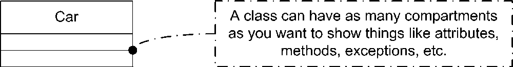
You represent a class with a rectangular box divided into compartments. A compartment is simply an area in the rectangle to write information. The first compartment holds the name of the class, the second holds attributes (see "Attributes“), and the third is used for operations (see "Operations“). You can hide any compartment of the class if that increases the readability of your diagram. When reading a diagram, you can make no assumptions about a missing compartment; it doesn’t mean it is empty. You may add compartments to a class to show additional information, such as exceptions or events, though this is outside of the typical notation.
UML suggests that the class name:
Start with a capital letter
Be centered in the top compartment
Be written in a boldface font
Be written in italics if the class is abstract (see "Abstract Classes“)
Figure 2-1 shows a simple class.
Objects
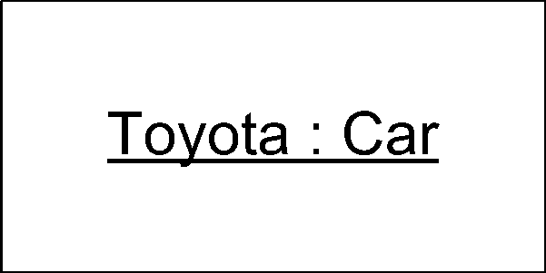
An object is an instance of a class. For example, you may have several instances of a class named Car: one two-door red car, one four-door blue car, and one hatchback green car. Each instance of Car is an object and may be given its own name, though it is common to see unnamed, or anonymous, objects on object diagrams. Typically you show the name of the object followed by a colon followed by its type (i.e., class). You show that this is an instance of a class by underlining the name and type. Figure 2-2 shows an instance of a class Car named Toyota. Note that in this figure, we have hidden the empty compartments.
Attributes
Details of a class (the color of a car, the number of sides in a shape, etc.) are represented as attributes . Attributes can be simple primitive types (integers, floating-point numbers, etc.) or relationships to other, complex objects (see "Relationships“).
An attribute can be shown using two different notations: inlined or relationships between classes. In addition, notation is available to show such things as multiplicity, uniqueness, and ordering. This section introduces both notations, and then describes the details of the attribute specification.
Inlined Attributes
You can list a class’s attributes right in rectangle notation; these are typically called inlined attributes . There is no semantic difference between inlined attributes and attributes by relationship; it’s simply a matter of how much detail you want to present (or, in the case of primitives like integers, how much detail you can present).
To represent an attribute within the body of a class, place the attribute in the second compartment of the class. UML refers to inlined attributes as attribute notation . Inlined attributes use the following notation:
visibility/name:typemultiplicity=default{property strings and constraints} visibility ::= {+|-|#|~} multiplicity ::= [lower..upper]
Figure 2-3 lists several attributes, demonstrating various aspects of attribute notation.
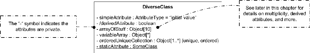
The syntax elements are:
-
visibility Indicates the visibility of the attribute. Use the following symbols: +, -, #, or ~ for
public,private,protected, orpackage, respectively (see "Visibility" in Chapter 3).- /
Indicates the attribute is derived . A derived attribute is simply one that can be computed from other attributes of the class. See "Derived Attributes.”
-
name Is a noun or short phrase naming the attribute. Typically the first letter is lowercase, and the first letter of each subsequent word is capitalized.
-
type Is the type of the attribute as another classifier, typically a class, interface, or built-in type like
int.-
multiplicity Specifies how many instances of the attribute’s type are referenced by this attribute. Can be absent (meaning multiplicity of 1), a single integer, or a range of values specified between square brackets separated by “..”. Use
*as the upperbound to represent the upper limit or*on its own to mean zero or more. See "Multiplicity.”-
default Is the default value of the attribute.
-
property strings Is a collection of properties, or tags, that can be attached to attributes. These are typically context-specific and denote such things as ordering or uniqueness. They are surrounded by
{}and separated by commas. See “Properties.”-
constraints Are one or more restrictions placed on an attribute. They may be natural language or use a formal grammar such as the OCL. See "Constraints.”
Attributes by Relationship
You may also represent attributes using the relationship notation. The relationship notation results in a larger class diagram, but it can provide greater detail for complex attribute types. The relationship notation also conveys exactly how the attribute is contained within a class (see "Relationships" for information on the types of relationships). For example, if you are modeling a Car, you can show that a car contains an Engine much more clearly using relationships than you can just by listing an attribute in the Car’s rectangle. However, showing the Car’s name by relationship is probably overkill because it is likely just a string.
To represent an attribute using relationships you use one of the association relationships between the class containing the attribute and the class that represents the attribute, as shown in Figure 2-4, which shows that the relationship between a car and its engine has a multiplicity of 1; a car has one engine.
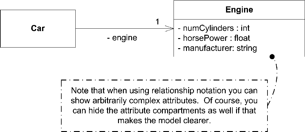
Tip
Yes, yes, as my editor pointed out, some cars like the Toyota Prius have two engines. Work with me here.
Relationship notation supports the same syntax as inlined notation, though the layout is slightly different. The attribute’s visibility and name are placed near the relationship line. Don’t use square brackets for multiplicity, but do place the multiplicity specification near the attribute’s classifier.
Like multiplicity, you can place constraints on attributes (see "Constraints“). In relationship notation, you write constraints near the attribute’s classifier along the relationship line. UML allows relationship notation to also express constraints between attributes, as shown in Figure 2-5.
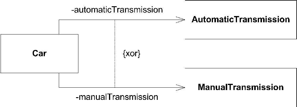
In Figure 2-5, the standard UML constraint xor shows that only automaticTransmission or manualTransmission can be set at any given time (exclusive or). You need to express this constraint in a note if the inlined attribute notation was used.
Derived Attributes
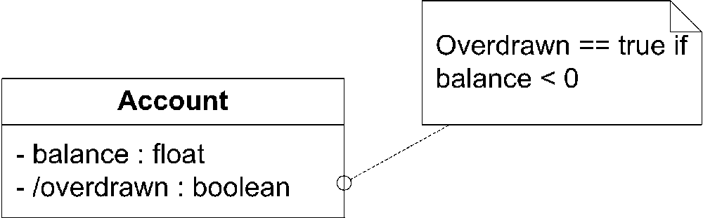
The derived notation, which is the leading forward slash (/), can be used as an indicator to the implementer that the attribute may not be strictly necessary. For example, let’s say you modeled a bank account with a simple class named Account. This class stores the current balance as a floating-point number named balance. To keep track of whether this account is overdrawn, you add a boolean named overdrawn. Whether the account is overdrawn is really based on whether the balance is positive, not the boolean you added. You can indicate this to the developer by showing that overdrawn is a derived attribute, with its state based on balance. Figure 2-6 shows how balance and overdrawn can be represented using a note to convey the relationship.
The UML specification notes that a derived attribute is typically readOnly, meaning a user may not modify the value. However, if a user is permitted to modify the value, the class is expected to update the source of the derived information appropriately.
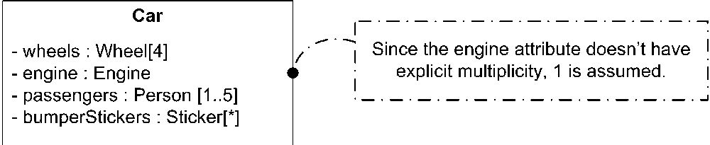
Attribute Multiplicity
The multiplicity of an attribute specifies how many instances of the attribute’s type are created when the owning class is instantiated. For example, our Car class will likely have four wheels, so the multiplicity of the wheel attribute is 4. If no multiplicity is specified, 1 is implied. Multiplicity can be a single integer, a list of integers separated by commas, or a range of values. When specifying a range of values, an infinite upper bound can be represented as an *; if no lower bound is specified, an * means zero or more. The multiplicity value
is shown between square brackets as a single integer or as two integers separated by two dots (..). Figure 2-7 shows the various ways to represent an attribute’s multiplicity.
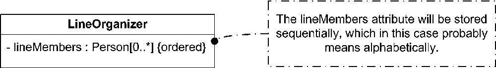
Ordering
An attribute with a multiplicity greater than 1 can be specified to be ordered. If the attribute is ordered, the elements must be stored sequentially. For example, you can specify that a list of names be stored alphabetically by marking the list as ordered. Exactly what it means for attributes to be stored sequentially typically depends on the attribute type. By default, attributes are not ordered. To mark an attribute as ordered, specify the property ordered after the attribute in braces, as shown in Figure 2-8.
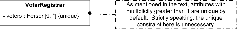
Uniqueness
In addition to being ordered, an attribute with multiplicity greater than 1 may be required to be unique. If an attribute is required to be unique, each element of this attribute must be unique. By default, attributes with multiplicity greater than 1 are unique, meaning there can be no duplicates in the elements this attribute holds. For example, if a class held a list of voters and each person was allowed to vote only once, each element in the list would be unique. To make an attribute unique, place the keyword unique after the attribute in braces, as shown in Figure 2-9. To allow an attribute to hold duplicates of an object, simply use the property not
unique.
Collection types
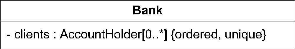
The UML specification specifies a set of mappings from the various ordered and uniqueness properties to UML collection types. Table 2-1 shows the mappings from attribute properties to the UML collection type. Note that the collection types shown in Table 2-1 are UML mappings and may not map directly to classes in a target language.
For example, to show that a bank’s clients should be represented using an OrderedSet, you can model the clients attribute as shown in Figure 2-10.
Attribute Properties
In addition to the properties associated with multiplicity, an attribute may have a number of properties set to convey additional information to the reader of the diagram. The common properties defined by UML are:
- readOnly
Specifies that the attribute may not be modified once the initial value is set. This typically maps to a constant in a development language. UML doesn’t specify when the initial value must be set, though if you specify the default value for an attribute it is considered the initial value and may not be changed.
- union
Specifies that the attribute type is a union of the possible values for this attribute. Frequently this is used with the
derivedproperty to indicate that an attribute is a derived union of another set of attributes.- subsets <attribute-name>
Specifies that this attribute type is a subset of all the valid values for the given attribute. This isn’t a common property, but if used, it is typically associated with subclasses of an attribute type.
- redefines <attribute-name>
Specifies that this attribute acts as an alias for the given attribute. Though uncommon, this attribute can be used to show that a subclass has an attribute that is an alias for a superclass’s attribute.
- composite
Specifies that this attribute is part of a whole-part relationship with the classifier. See "Relationships" for more information on composition.
Constraints
Constraints represent restrictions placed on an element. They may be natural language or use a formal grammar such as the OCL; however, they must evaluate to a boolean expression. You typically show constraints between curly braces ({}) after the element they restrict, though they may be placed in a note and linked to the element using a dashed line.
You can name a constraint by specifying the name followed by a colon (:) before the boolean expression. This is frequently used to identify constraints on
an operation (see "Operation Constraints“).
Figure 2-11 shows several constraints on attributes and operations.

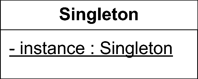
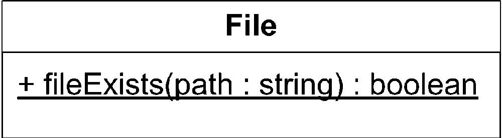
Static Attributes
Static attributes are attributes of the class rather than of an instance of the class. For example, you can initialize constant values for a class and share them between all instances of the class. You represent static attributes by underlining their specification in both inlined and relationship-based presentations, as shown in Figure 2-12.
Operations
Operations are features of classes that specify how to invoke a particular behavior. For example, a class may offer an operation to draw a rectangle on the screen or count the number of items selected in a list. UML makes a clear distinction between the specification of how to invoke a behavior (an operation) and the actual implementation of that behavior (a method). See "Methods" for more information.
You place operations in a separate compartment with the following syntax:
visibility name ( parameters ) : return-type {properties}where parameters are written as:
            direction parameter_name : type [ multiplicity ]
  = default_value { properties }
Figure 2-13 shows several example operations on a class.
-
visibility Indicates the visibility of the operation. Use the following symbols: +, -, #, or ~ for
public,private,protected, orpackage, respectively (see "Visibility" in Chapter 3).-
name Is a short phrase naming the operation. Operations are usually verb phrases representing actions the classifier should perform on behalf of the caller. The UML specification recommends that the first letter of an operation be lowercase, with all of the following words starting with a capital letter and running together. See Figure 2-13 for an example.
-
return-type Is the type of information the operation will return, if any. If no information is returned from the operation (called a
subroutinein some development languages), the return type should bevoid. If the operation does return a value (called afunctionin some development languages), you should show the type of the returned value, such as another classifier, a primitive type, or a collection. The UML specification states that the return type is optional. If it’s left off, you can’t assume anything about the return value of the operation, or even if one exists.-
properties Specifies constraints and properties associated with an operation. These are optional; if you don’t use properties you don’t show the curly braces. See "Operation Constraints" for more information.
Parameter syntax elements are:
-
direction An optional part of the syntax that indicates how a parameter is used by an operation. It is one of
in,inout,out, orreturn.instates that the parameter is passed to the operation by the caller.inoutstates that the parameter is passed by the caller and is then possibly modified by the operation and passed back out.outstates that the parameter isn’t set by the caller but is modified by the operation and is passed back out.returnindicates that the value set by the caller is passed back out as a return value.-
parameter_name Is a noun or noun phrase naming the parameter. Typically the parameter name starts with a lowercase letter, with any subsequent words starting with a capital letter.
-
type Is the type of the parameter. This is typically another class, interface, collection, or primitive type.
-
multiplicity Specifies how many instances of the parameter’s type are present. Can be absent (meaning multiplicity of 1), a single integer, a list of integers separated by commas, or a range of values specified between square brackets separated by “..”. An infinite upper bound can be represented as an
*; if no lower bound specified, an*means zero or more. See "Multiplicity.”-
default_value Specifies the default value of this parameter. The default value is optional. If it isn’t present, you don’t show the equals sign. Note that UML doesn’t specify if a parameter with a default value may be left out when invoking an operation (e.g., C++’s default parameter value implementation). The actual syntax for invoking an operation is language-dependent.
-
properties Specifies any parameter-related properties and is specified between curly braces. These are typically defined within the context of a specific model, with a few exceptions:
ordered,readOnly, andunique. See "Multiplicity" and “Properties” for more information. Properties are optional for parameters; if they aren’t used, don’t show the curly braces.
Operation Constraints
An operation may have several constraints associated with it that help define how the operation interacts with the rest of the system. Together, constraints on an operation establish a contract that an implementation of the operation must obey.
Constraints on an operation follow the usual constraint notation and are placed either immediately after the operation signature or in a note attached with a dashed line. See "Constraints" for more information.
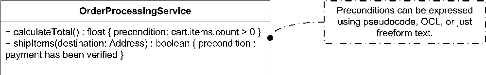
Preconditions
Preconditions capture what the state of the system must be before an operation can be invoked. Practically speaking, you really can’t express the state of the entire system. Instead, preconditions typically express the valid values for parameters, the state of the class owning the operation, or a few key attributes of the system.
The specification explicitly states that the operation doesn’t need to check the preconditions in the body of the operation before executing; theoretically the operation will not even be invoked if the preconditions aren’t met. In practice, few languages offer such protection. If someone took the time to express them, it is usually in your best interest to verify the preconditions are correct when implementing an operation.
As a developer, preconditions offer you one of the few chances to “cover your butt” and say exactly how you expect things to be when your implementation is invoked; use them.
Figure 2-14 shows several examples of preconditions.
Postconditions
Postconditions capture guarantees about the state of the system after an operation has executed. Like preconditions, postconditions typically express the state of one or more key attributes of the system, or some guarantee about the state of the class owning the operation.
Figure 2-15 shows example postconditions linked to an operation.

Body conditions
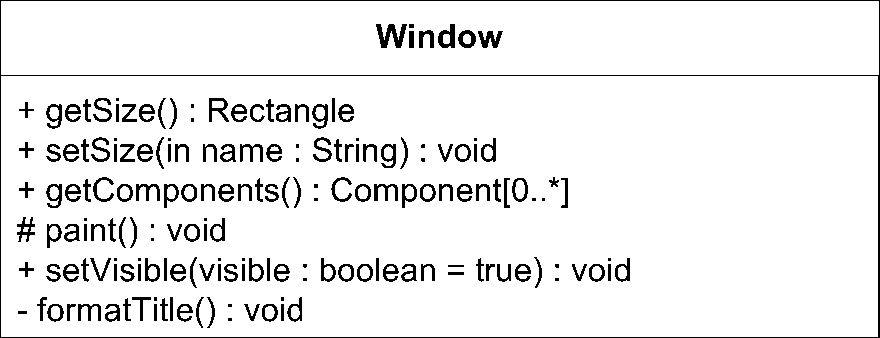
An operation may have a bodyCondition that constrains the return value. The bodyCondition is separate from the postcondition because the bodyCondition may be replaced by methods of subclasses of the owning class. (See "Generalization" for more information on subclasses.) For example, a class named Window may specify a body condition for a method named getSize() that requires the length and width of a window be nonzero. A subclass named SquareWindow may provide its own body condition stating that the width must equal the height. The bodyCondition is similar to the pre- and postconditions in that the constraint may be expressed in natural language or in OCL. See "Constraints" for more information. Figure 2-16 shows an example of a bodyCondition on an operation.

Query operations
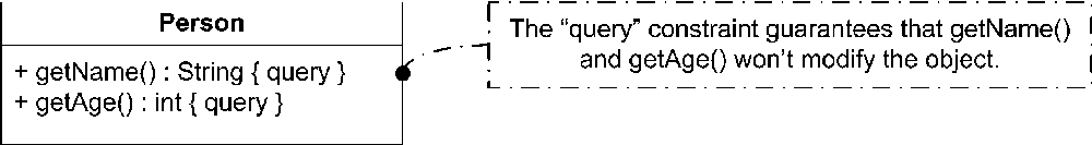
An operation may be declared as a query operation if the implementation of the operation doesn’t modify the owning class in any way. In practice, modelers often use the query property to indicate a method that doesn’t change any meaningful attribute of an object. For example, there may be internal cache attributes that are updated as a result of a query. The important thing is that the state of the system, from an external perspective, isn’t changed by the query method; there can be no side effects to calling the method.
You indicate a query method by placing the query constraint after the operation signature. For example, an operation named getAge() that simply returns an integer without changing any internal value of the owning class would be considered a query method. In C++, this typically maps to a const method. Figure 2-17 shows several query methods on a class.
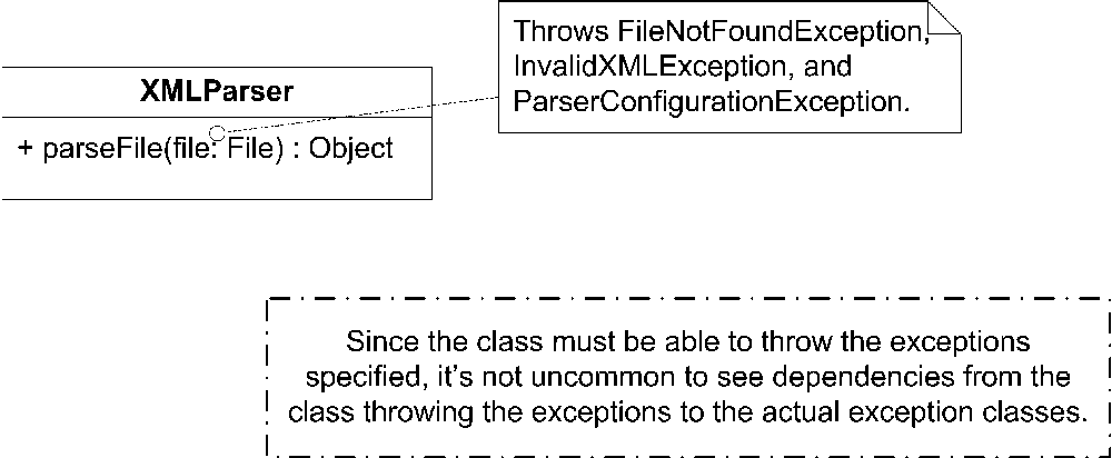
Exceptions
While they’re technically not constraints, you may express exceptions thrown by an operation using similar notation. Exceptions are typically other classes (often stereotyped with the keyword «exception», though this is simply by convention) that are thrown by an operation in the event of an error. You can list thrown exceptions in a note attached to an operation using a dashed line. Figure 2-18 shows an example of an operation that throws several exceptions.
Static Operations
Operations typically specify behavior for an instance of a class. However, UML allows for an operation to specify behavior for the class itself. These operations are called static operations and are invoked directly on the class, not on an instance. Static operations are frequently used as utility operations that don’t need to use the attributes of the owning class. UML doesn’t formally discuss the notation of these operations, but it is typical to see them represented with the same convention as static attributes. You indicate an operation is static by underlining the operation signature. Figure 2-19 shows an example of a static operation.
Methods
A method is an implementation of an operation. Each class typically provides an implementation for its operations or inherits them from its superclass (see "Generalization“). If a class doesn’t provide an implementation for an operation, and one isn’t provided by its superclass, the operation is considered abstract . See "Abstract Classes" for more information. Because methods are implementations of operations, there is no notation for a method; simply show an operation on a class.
Abstract Classes
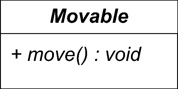
An abstract class is typically a class that provides an operation signature, but no implementation; however, you can have an abstract class that has no operations at all. An abstract class is useful for identifying common functionality across several types of objects. For example, you can have an abstract class named Movable. A Movable object has a current position and the ability to move somewhere else using an operation named move(). There can be several specializations of this abstract class—a Car, a Grasshopper, and a Person, each of which provides a different implementation of move(). Because the base class Movable doesn’t have an implementation for move(), the class is said to be abstract.
You show a class is abstract by writing its name in italics. Show each abstract operation in italics as well. Figure 2-20 is an example of the abstract class Movable.
An abstract class can’t be instantiated; it must be subclassed and then a subclass which does provide the operation implementation can be instantiated. See "Relationships" for more information on subclasses.
Relationships
Classes in isolation would not provide much insight into how a system is designed. UML provides several ways of representing relationships between classes. Each of UML relationship represents a different type of connection between classes and has subtleties that aren’t fully captured in the UML specification. When modeling in the real world, be sure that your intended viewers understand what you are conveying with your various relationships. We say this both as a warning to the modeler and as a slight disclaimer that the following explanations are our interpretation of the UML specification. For example, the debate over when to use aggregation versus composition is ongoing. To help determine which relationship is most appropriate, we offer a short phrase for each type that may help make the distinction. Again, the important thing is to be consistent within your model.
Dependency
The weakest relationship between classes is a dependency relationship. Dependency between classes means that one class uses, or has knowledge of, another class. It is typically a transient relationship, meaning a dependent class briefly interacts with the target class but typically doesn’t retain a relationship with it for any real length of time.
Dependencies are typically read as “...uses a...”. For example, if you have a class named Window that sends out a class named WindowClosingEvent when it is about to be closed, you would say "Window uses a WindowClosingEvent.”
You show a dependency between classes using a dashed line with an arrow pointing from the dependent class to the class that is used. Figure 2-21 shows a dependency between a class named Window and a class named WindowClosingEvent.
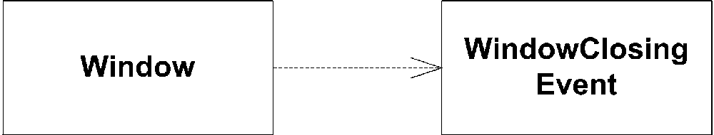
You can likely assume from Figure 2-21 that Window doesn’t retain a relationship with a WindowClosingEvent for any real length of time. It simply uses them when needed and then forgets about them.
Association
Associations are stronger than dependencies and typically indicate that one class retains a relationship to another class over an extended period of time. The lifelines of two objects linked by associations are probably not tied together (meaning one can be destroyed without necessarily destroying the other).
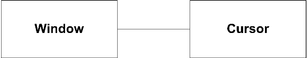
Associations are typically read as “...has a...”. For example, if you have a class named Window that has a reference to the current mouse cursor, you would say "Window has a Cursor“. Note that there is a fine line between “...has a...” and “...owns a...” (see "Aggregation" later in this section). In this case, Window doesn’t own the Cursor; Cursor is shared between all applications in the system. However, Window has a reference to it so that the Window can hide it, change its shape, etc. You show an association using a solid line between the classes participating in the relationship. Figure 2-22 shows an association between Window and Cursor.
Navigability
Associations have explicit notation to express navigability. If you can navigate from one class to another, you show an arrow in the direction of the class you can navigate to. If you can navigate in both directions, it is common practice to not show any arrows at all, but as the UML specification points out, if you suppress all arrows you can’t distinguish nonnavigable associations from two-way associations. However, it is extremely rare to use a nonnavigable association in the real world, so this is unlikely to be a problem.
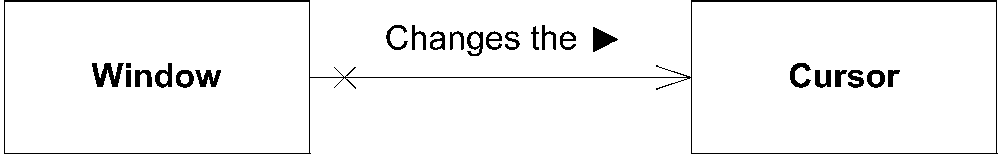
You can explicitly forbid navigation from one class to another by placing a small X on the association line at the end of the class you can’t navigate to. Figure 2-23 shows an association between a class named Window and a class named Cursor. Because you can’t navigate from an instance of Cursor to an instance of Window, we explicitly show the navigability arrow and an X where appropriate.

Naming an association
Associations may be adorned with several symbols to add information to your model. The simplest is a solid arrowhead showing the direction in which the viewer should read the association. It is common to include a short phrase along with the arrowhead to provide some context for the association. The phrase used with the association doesn’t typically generate into any form of code representation; it is purely for modeling purposes. Figure 2-24 shows the solid arrowhead on the Window to Cursor association.
Multiplicity
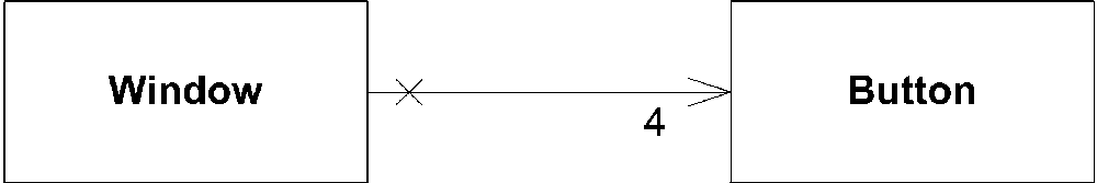
Because associations typically represent lasting relationships, they are often used to indicate attributes of a class. As mentioned in the “Attributes by Relationship” section, you can express how many instances of a particular class are involved in a relationship. If you don’t specify a value, a multiplicity of 1 is assumed. To show a different value, simply place the multiplicity specification near the owned class. See "Attribute Multiplicity" for the allowable multiplicity types. Note that when you use multiplicity with an association, you don’t use square brackets around the values. Figure 2-25 shows an association with explicit multiplicity.
The properties related to multiplicity may be applied to associations as well. See “Properties” for the names and definitions of allowed properties.
Aggregation
Aggregation is a stronger version of association. Unlike association, aggregation
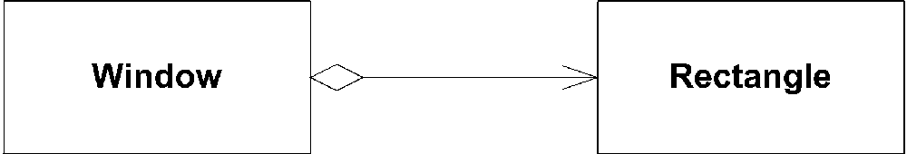
typically implies ownership and may imply a relationship between lifelines. Aggregations are usually read as “...owns a...”. For example, if you had a classed named Window that stored its position and size in a Rectangle class, you would say the "Window owns a Rectangle.” The rectangle may be shared with other classes, but the Window has an intimate relationship with the Rectangle. This is subtly different from a basic association; it has a stronger connotation. However, it’s not the strongest relationship you can have between classes. If the relationship is more of a whole part (class A “...is part of...” class B), you should look at composition
.
You show an aggregation with a diamond shape next to the owning class and a solid line pointing to the owned class. Figure 2-26 shows an example aggregation between a class named Window and a class named Rectangle.
As with the association relationship, you can show navigability and multiplicity on an aggregation line. See "Association" for examples.
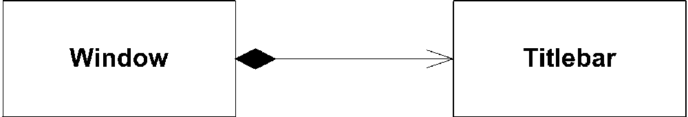
Composition
Composition represents a very strong relationship between classes, to the point of containment. Composition is used to capture a whole-part relationship. The “part” piece of the relationship can be involved in only one composition relationship at any given time. The lifetime of instances involved in composition relationships is almost always linked; if the larger, owning instance is destroyed, it almost always destroys the part piece. UML does allow the part to be associated with a different owner before destruction, thus preserving its existence, but this is typically an exception rather than the rule.
A composition relationship is usually read as “...is part of...”, which means you need to read the composition from the part to the whole. For example, if you say that a window in your system must have a titlebar, you can represent this with a class named Titlebar that “...is part of...” a class named Window.
You show a composition relationship using a filled diamond next to the owning class and a solid line pointing to the owned class. Figure 2-27 shows an example composition relationship between a class named Window and a class named Titlebar.
As with the association relationship, you can show navigability and multiplicity on a composition line. See "Association" for examples.
Generalization
A generalization
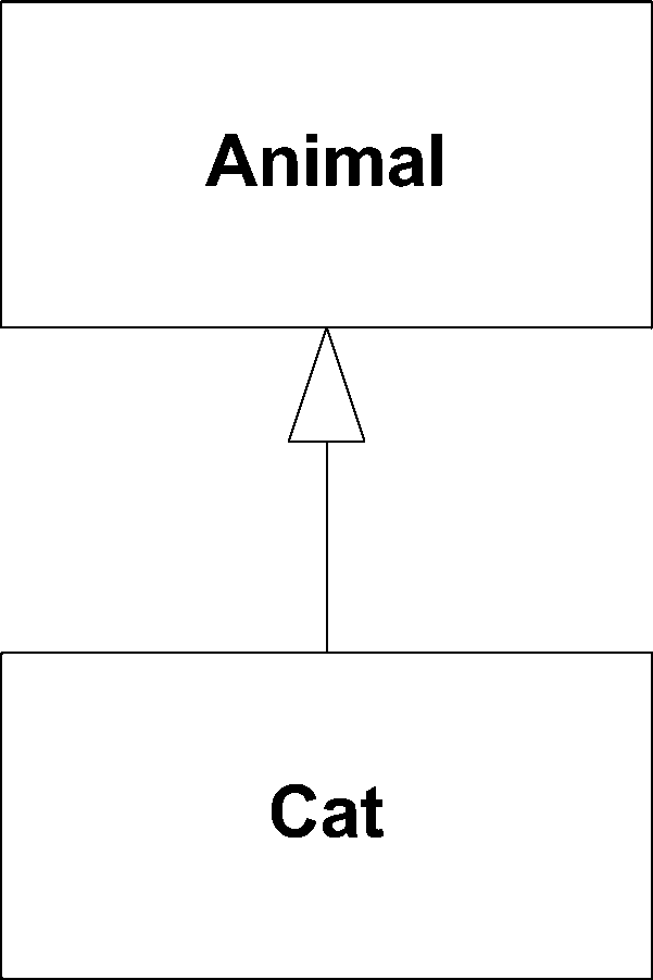
relationship conveys that the target of the relationship is a general, or less specific, version of the source class or interface. Generalization relationships are often used to pull out commonality between difference classifiers. For example, if you had a class named Cat and a class named Dog, you can create a generalization of both of those classes called Animal. A full discussion of how and when to use generalization (especially versus interface realization) is the subject for an object-oriented analysis and design book and isn’t covered here.
Generalizations are usually read as “...is a...”, starting from the more specific class and reading toward the general class. Going back to the Cat and Dog example, you would say “a Cat...is a...Animal" (grammar aside).
You show a generalization relationship with a solid line with a closed arrow, pointing from the specific class to the general class. Figure 2-28 shows an example of the Cat to Animal relationship.
Unlike associations, generalization relationships are typically not named and don’t have any kind of multiplicity. UML allows for multiple inheritance, meaning a class can have more than one generalization with each representing an aspect of the decedent class. However, some modern languages (e.g., Java and C#) don’t support multiple inheritance; interfaces and interface realization are used instead.
Association Classes
Often the relationship between two elements isn’t a simple structural connection. For example, a football player may be associated with a league by virtue of being on a team. If the association between two elements is complex, you can represent the connection using an association class. An association class is an association that has a name and attributes, like a normal class. You show an association class like a regular class with a dashed line connecting it to the association it represents. Figure 2-29 shows a football player’s relationships to a league.
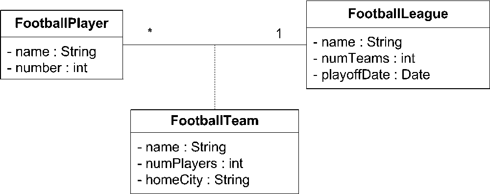
When translated into code, relationships with association classes
often result in three classes: one for each end of the association and one for the association class itself. There may or may not be a direct link between the association ends; the implementation may require you to traverse through the association class to get to the opposite end of the link. In other words, FootballPlayer may not have a direct reference to FootballLeague but may have a reference to FootballTeam instead. FootballTeam would then have a reference to FootballLeague. How the relationships are constructed is a matter of implementation choices; however, the fundamental concept of an association class is unchanged.
Association Qualifiers
Relationships between elements are often keyed, or indexed, by some other value. For example, a bank patron may be identified by her account number, or a tax payer by his Social Security number. UML provides association qualifiers to capture such information. A qualifier is typically an attribute of the target element, though this isn’t required. You show a qualifier by placing a small rectangle between the association and the source element. Draw the name of the qualifier (usually the name of an attribute) in the rectangle. Figure 2-30 shows the relationship between the IRS and a taxpayer qualified by the taxpayer’s Social Security number.
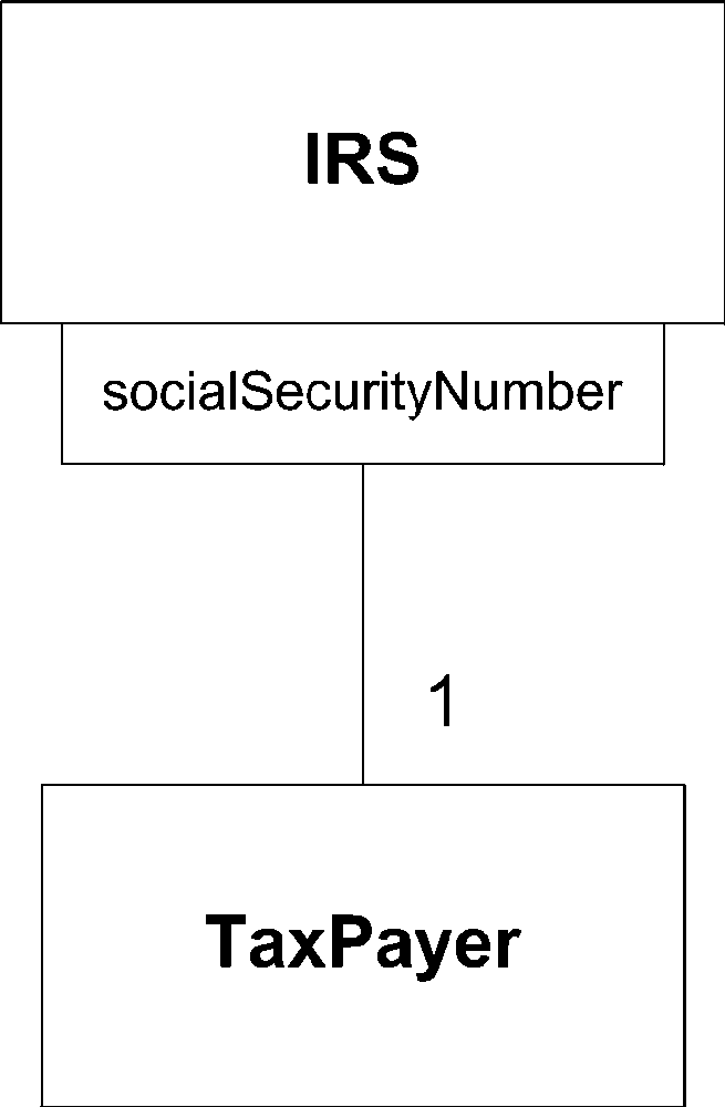
Notice that the multiplicity between the association qualifier and TaxPayer is 1. Obviously the IRS is associated with more than one TaxPayer, but by using qualifiers, you indicate that a socialSecurityNumber uniquely identifies a single TaxPayer within the IRS.
Interfaces
An interface is a classifier that has declarations of properties and methods but no implementations. You can use interfaces
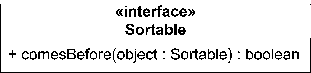
to group common elements between classifiers and provide a contract a classifier that provides an implementation of an interface must obey. For example, you can create an interface named Sortable that has one operation named comesBefore(...). Any class that realizes the Sortable interface must provide an implementation of comesBefore(...).
Some modern languages, such as C++, don’t support the concept of interfaces; UML interfaces are typically represented as pure abstract classes. Other languages, such as Java, do support interfaces but don’t allow them to have properties. The moral is that you should be aware of how your model is going to be implemented when modeling your system.
There are two representations for an interface; which one you should use depends on what you’re trying to show. The first representation is the standard UML classifier notation with the stereotype «interface». Figure 2-31 shows the Sortable interface.
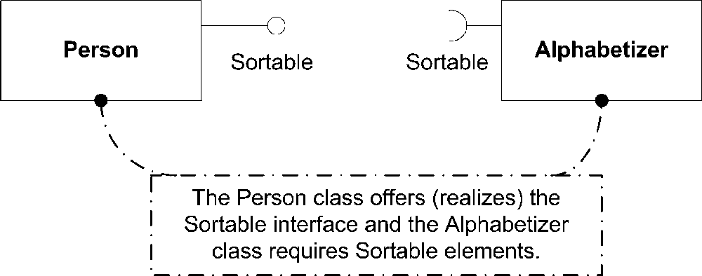
The second representation of an interface is the ball-and-socket notation. This representation shows less detail for the interface but is more convenient for showing relationships to classes. The interface is simply shown as a ball with the name of the interface written below it. Classes dependent on this interface are shown attached to a socket matching the interface. Figure 2-32 shows the Sortable interface using the ball-and-socket notation.
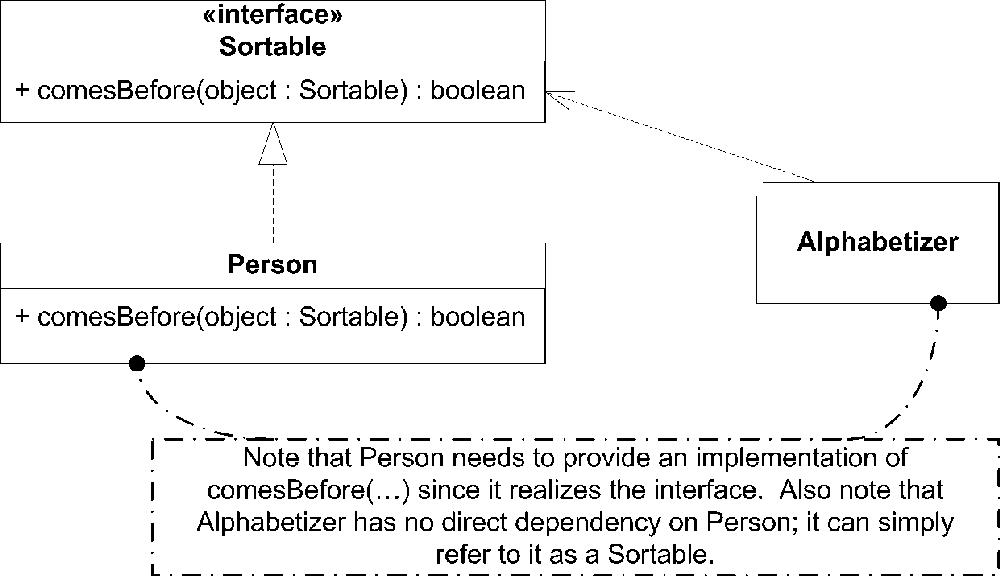
Because an interface specifies the contract only for a set of features, you can’t instantiate an interface directly. Instead, a class is said to realize an interface if it provides an implementation for the operations and properties. You show realization using a dashed line starting at the realizing classifier and leading to the interface, with a closed arrowhead at the end. Classes that are dependent on the interface are shown using a dashed line with an open arrow (dependency). Figure 2-33 shows a class that realizes the Sortable interface and a class that is dependent on it.
Providing an implementation of an operation is straightforward. You must provide an implementation on a realizing classifier with the same signature as the operation on the interface. Typically there are semantic constraints associated with an operation that must be honored by any implementation. Realizing a property is more subtle. A property on an interface states that any class that realizes the interface must store the data specified by the property in some way. A property on an interface doesn’t necessarily mean there will be an associated property on a realizing classifier. However, the classifier must be able to store the data represented by the property and provide a means to manipulate it.
Templates
Just as interfaces allow you to provide specifications for objects your class will interact with, UML allows you to provide abstractions for the type of class your class may interact with. For example, you can write a List class that can hold any type of object (in C++ this would probably be a void*, in Java and C# it would probably be an Object). However, while you wanted your List class to be able to support any type of object, you want all of the objects in a given list to be of the same type. UML allows you to create and specify these kinds of abstractions using templates
.
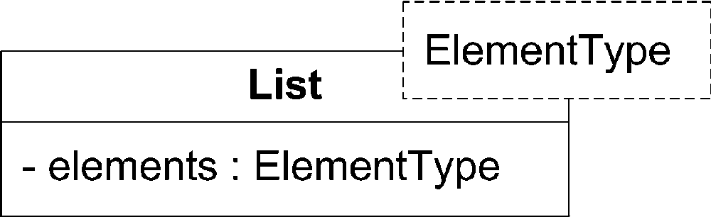
You can indicate that a class is a templated (also called parameterized
) class by drawing a dashed rectangle in the upper-right corner of the class. For each element you would like to template, you need to specify a name to act as a placeholder for the actual type. Write the placeholder name in the rectangle. Figure 2-34 shows an example of a List class that can support any type.
Tip
This example uses ElementType as the name of the templated type for clarity. In practice, this is often abbreviated to just T.
You can have multiple templated types within a single class; just separate the type names with a comma (,). If you need to restrict the types the user may substitute, show that with a colon (:) followed by the type name. Figure 2-35 shows a more complicated version of the List class that requires a Sorter along with the type of object to store in the list.
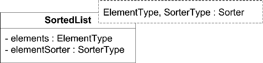
Specifying restrictions on a type that may be used is functionally similar to specifying an interface for a templated member, except that the user may be able to further restrict an instance of your class by specifying a subclass of your type.
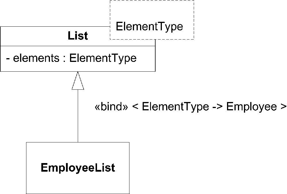
When a user creates an instance of a List, she needs to specify the actual type to use in place of ElementType. This is called binding
a type to a template. You show binding with the keyword «bind», followed by a type specification using the following syntax:
<TemplatedType->RealType>
You can use the binding syntax whenever you refer to a templated class to indicate you want to use a bound version of that class. This is called explicit binding
. For example, Figure 2-36 shows a subclass of List called EmployeeList that binds the ElementType of List to a class named Employee.
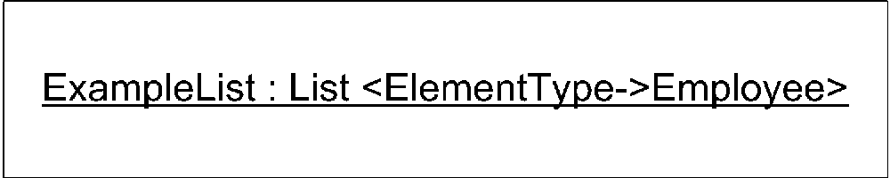
The bind keyword also indicates what types should be used with an instance of a template. This is called implicit binding
and is shown in Figure 2-37.
Variations on Class Diagrams
Because class diagrams model structures well, they can be used to capture well-defined, hierarchical information. Class diagrams have been used to capture XML and database schemas with some degree of success. In the interest of full disclosure, people who deal with XML and database schemas extensively have reservations about using class diagrams to capture the information, specifically because class diagrams are so generic. Each domain has its own notation that may be better suited to capturing complex relationships or domain-specific information. However, UML has the benefit of being a common language that is understood by those outside the XML and database domains.
XML Schemas
The structural design of an XML document can be captured in an XML schema. XML schemas are to XML documents as classes are to objects; XML documents are instances of a schema. Therefore, it’s not a giant leap to realize that class diagrams can be used to model XML schemas. XML schemas are described using the XML Structure Definition Language (XSDL). XSDL is a text language (as opposed to the graphical nature of UML) and can be verbose; mapping XSDL to UML can make it much easier to digest a schema document.
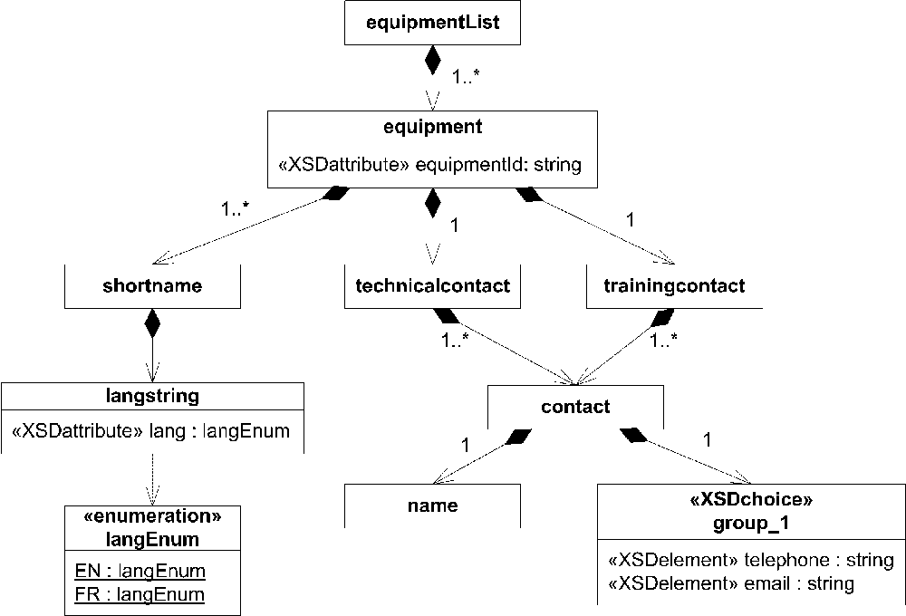
The fundamental elements of XSDL are XML elements, which are connected in sequences, choices, and complex structures. Each element may have extra information attached to it using (conveniently enough) attributes. Modelers typically represent XML elements as classes and XSDL attributes as UML attributes. Each element is linked to the next using composition arrows. Multiplicity specifications on the relationships show how many times one element appears within another. Example 2-1 is a sample XML document that describes a piece of equipment.
<?xml version="1.0" encoding="UTF-8"?>
<equipmentlist xmlns:xsi="http://www.w3.org/2001/XMLSchema-instance"
    xsi:noNamespaceSchemaLocation="equipment.xsd">
    <equipment equipmentid="H-1">
        <shortname>
            <langstring lang="en">Hammer</langstring>
        </shortname>
        <technicalcontact>
            <contact>
                <name>Ron</name>
                <telephone>555-1212</telephone>
            </contact>
        </technicalcontact>
        <trainingcontact>
            <contact>
                <name>Joe</name>
                <email>[email protected]</email>
            </contact>
        </trainingcontact>
    </equipment>
</equipmentlist>
Example 2-2 is the XSDL that describes the XML document.
<?xml version="1.0" encoding="ISO-8859-1"?>
<xs:schema xmlns:xs="http://www.w3.org/2001/XMLSchema"
    elementFormDefault="qualified">

   <!-- ~Class: contact ~~~~~~~~~~~~~~~~~~~~~~~~~~~~~~~~~ -->
   <xs:element name="contact" type="contact"/>
   <xs:complexType name="contact">
      <xs:sequence>
        <xs:element name="name" type="xs:string"/>
        <xs:choice>
          <xs:element name="telephone" type="xs:string"/>
          <xs:element name="email" type="xs:string"/>
        </xs:choice>
      </xs:sequence>
   </xs:complexType>

   <!-- ~Class: equipment ~~~~~~~~~~~~~~~~~~~~~~~~~~~~~~~ -->
   <xs:element name="equipment" type="equipment"/>
   <xs:complexType name="equipment">
      <xs:sequence>
         <xs:element ref="shortname"/>
         <xs:element name="technicalcontact" type="technicalcontact"/>
         <xs:element name="trainingcontact" type="trainingcontact"/>
      </xs:sequence>
      <xs:attribute name="equipmentid" type="xs:string" use="required"/>
   </xs:complexType>

   <!-- ~Class: equipmentlist ~~~~~~~~~~~~~~~~~~~~~~~~~~~ -->
   <xs:element name="equipmentlist" type="equipmentlist"/>
   <xs:complexType name="equipmentlist">
      <xs:sequence>
         <xs:element ref="equipment" minOccurs="1" maxOccurs="unbounded"/>
      </xs:sequence>
   </xs:complexType>

   <!-- ~Class: <<XSDtopLevelAttribute>> lang~~~~~~~~~~~~ -->
   <xs:attribute name="lang" type="xs:language"/>

   <!-- ~Class: langstring ~~~~~~~~~~~~~~~~~~~~~~~~~~~~~~ -->
   <xs:element name="langstring" type="langstring"/>
   <xs:complexType name="langstring">
      <xs:simpleContent>
         <xs:extension base="xs:string">
            <xs:attribute name="lang" use="required">
               <xs:simpleType>
                  <xs:restriction base="xs:NMTOKEN">
                     <xs:enumeration value="en"/>
                     <xs:enumeration value="fr"/>
                  </xs:restriction>
               </xs:simpleType>
            </xs:attribute>
         </xs:extension>
      </xs:simpleContent>
   </xs:complexType>

   <!-- ~Class: shortname ~~~~~~~~~~~~~~~~~~~~~~~~~~~~~~~ -->
   <xs:element name="shortname" type="shortname"/>
   <xs:complexType name="shortname">
      <xs:sequence>
         <xs:element ref="langstring" minOccurs="1" maxOccurs="unbounded"/>
      </xs:sequence>
   </xs:complexType>

   <!-- ~Class: technicalcontact ~~~~~~~~~~~~~~~~~~~~~~~~ -->
   <xs:element name="technicalcontact" type="technicalcontact"/>
   <xs:complexType name="technicalcontact">
      <xs:sequence>
         <xs:element ref="contact" minOccurs="1" maxOccurs="unbounded"/>
      </xs:sequence>
   </xs:complexType>

   <!-- ~Class: trainingcontact ~~~~~~~~~~~~~~~~~~~~~~~~~ -->
   <xs:element name="trainingcontact" type="trainingcontact"/>
   <xs:complexType name="trainingcontact">
      <xs:sequence>
         <xs:element ref="contact" minOccurs="1" maxOccurs="unbounded"/>
      </xs:sequence>
   </xs:complexType>
   </xs:schema>
Figure 2-38 is a UML representation of the schema. Elements are represented as classes, with one exception: the contact definition includes a choice option. Figure 2-38 represents this using another class stereotyped as XSDchoice, and the options are represented as attributes of the class.
So, while UML simplifies a schema by representing the information graphically, details such as sequencing and type information can be lost without using a UML extension mechanism such as constraints or stereotypes.
Database Schemas
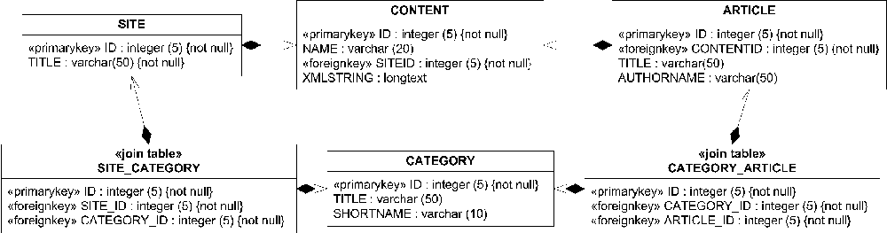
By mapping database tables to classes and table rows to attributes, you can capture a database schema fairly well using UML. Additional information such as primary keys , foreign keys, and constraints can be captured using UML constraints or stereotypes. You can show relationships between tables using associations between classes (usually composition relationships, but that is just by convention). Figure 2-39 shows a sample database schema represented using a UML class diagram.
As with XML schemas, few professional database administrators model databases using class diagrams. UML class diagrams are useful for conveying schema information in a common language, but they lack the expressive (and custom) capabilities of the more standard database notation, Entity Relation Diagrams (ERDs).