Chapter 4. Composite Structures
As a system becomes more complex, it is often helpful to decompose it in terms of functionality (see Chapter 7). To realize a piece of functionality, different elements of a system often work together and communicate information. UML 2.0 formalizes the concept of complex relationships between elements into the idea of composite structures. Much of the material in this chapter is new to UML 2.0.
Composite Structures
A structure is a set of interconnected elements that exist at runtime to collectively provide some piece of functionality. For example, you can use a structure to represent the internal makeup of a classifier such as a subsystem (what objects are related to each other, who is communicating with whom, etc.). UML calls such structures internal structures. UML defines several symbols to capture the relationships and communications between elements in an internal structure.
Connectors
Connectors represent communication links between instances of classes participating in an internal structure. They can be runtime instances of associations, or they can represent dynamic communication set up at runtime—for example by being values of local variables. You show a connector as a solid line between two instances. Note that while associations between classes represent a link between any instances of those classes, a connector represents a link between only the two instances specified at each end of the connector (see "Collaborations“).
You can provide name and type information for a connector using the following format:
name:classname
where:
-
name Is the name of the connector. The name can be used later in collaborations to reference this connector.
-
classname Is the name of an association this connector represents.
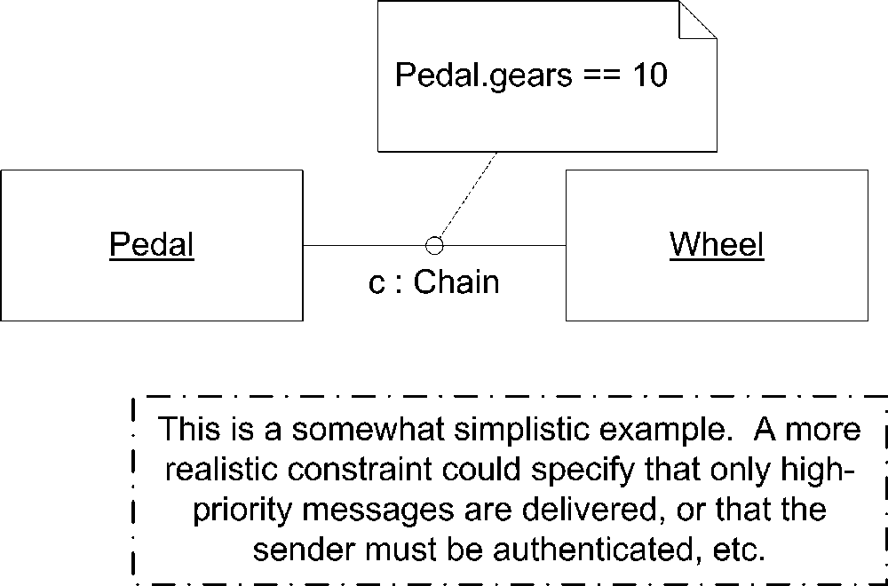
Figure 4-1 is an example of a named connector.

UML specifies several rules for determining the types of the elements at each end:
If a connector is an instance of an association, the types of the instances at either end of the connector must be the same types at either end of the association.
If an instance at one end of a connector has required interfaces, the instance at the other end of the connector must provide one of those interfaces.
If an instance at one end of a connector has required interfaces and a port is connected to the other end of the connector, the port must provide a required interface.
The actual means of communication isn’t specified by the connector; it can represent a simple method call or a complex protocol over a socket connection. You can constrain the connection using the normal UML note notation. Simply specify the constraint in a note, and link it to the connector using a dashed line. Figure 4-2 shows a constrained connector.
You may specify the multiplicity of each connector end using the normal multiplicity syntax. Simply write the number of instances for a given end near the end of the connector. For example, a student/teacher relationship may require at least 5 students and no more than 20. You can show the student/teacher relationship as depicted in Figure 4-3.

Ports
A port is a way to offer functionality from a composite structure without exposing the internal details of how that functionality is realized. For example, you may have a subsystem that can perform credit card payment verification. The actual implementation of this functionality may be spread over several classes working in conjunction. The organization of these classes can be represented as an internal structure within the subsystem, and the overall functionality, or credit card verification, can be exposed using a port. Exposing the functionality through a port allows the subsystem to be used by any other classifier that conforms to the port’s specifications. Starting with UML 2.0, classes have been extended to allow for ports and internal structures. By default, ports are public, however UML 2.0 allows you to have internal ports that are available only to the composite structure hosting them.
You show a port as a small square. You typically draw the name and multiplicity of the port near the square, though both may be hidden. If you draw the port on the edge of a classifier, the port is public and is available to the environment. If you draw the port inside a classifier, the port is protected and available only to the composite structure. Figure 4-4 shows an example port.

Required and provided interfaces
Ports are associated with required and provided interfaces (see "Interfaces" in Chapter 2). Required interfaces show what the owning classifier may ask of its environment through a given port. Provided interfaces show what functionality a classifier exposes to the environment. For example, our credit card payment system may provide an interface to verify credit cards, CreditCardProcessor, while requiring access to an account verification system, AccountServices, offered by the credit card company. If you use ports in your diagrams, the required and provided interfaces capture all the interaction the system may have with a given classifier. Provided and required interfaces are typically shown using the ball and socket (lollipop) notation, though you may explicitly type a port (see "Port typing“). If there are multiple required or provided interfaces, simply list each interface name followed by a comma; don’t show multiple lollipops. Figure 4-5 shows a port with a required interface and two provided interfaces.

Realizing port implementations
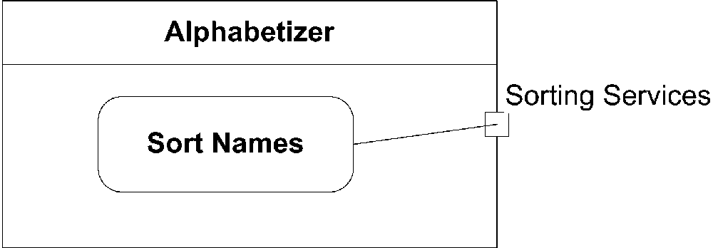
Ports are wired to an internal implementation using connectors. See "Connectors" for information on how to represent a connector. If the classifier owning the port provides the implementation of the functionality itself, the port is considered a behavioral port. In this case, the connector links to a state inside the classifier. This state is used to explain the behavior of the classifier when the port is used (see Chapter 8 for more information on using states to model behavior). This is typically used for simple classifiers (not complex structures) that implement functionality themselves. Figure 4-6 shows a behavioral port.
On the other hand, if the functionality is realized by internal elements, you link the connector to internal classifiers that provide the implementation. This is typically used for composite structures such as components and subsystems. Figure 4-7 shows such a port.

Multiple connectors
UML 2.0 allows you to have multiple connectors leading from a port to different internal elements. However, it doesn’t specify what happens when communication is received at that port; this is left up to the modeler. Some possible solutions are to forward the communication to all connectors, forward based on priority, forward on a round-robin basis, or simply randomly choose a connector. Regardless of your decision, be sure to document it in your model, probably using a note attached to the port. Figure 4-8 shows an example of using a port with many connectors.

Port multiplicity
A classifier may specify multiplicity for a port like any other element. Simply place the desired number of port instances in brackets after the port name and type (if present). When the classifier is instantiated, the associated ports are instantiated as well. These are called interaction points and can be uniquely identified by the classifier. For example, if your classifier has two ports, one with provided interfaces that offer anonymous access to data and one with a provided interface that offers authenticated access to data, your classifier can distinguish which port was used by the external system. Figure 4-9 shows the credit card verification system offering two instances of the credit card verification port.

Port typing
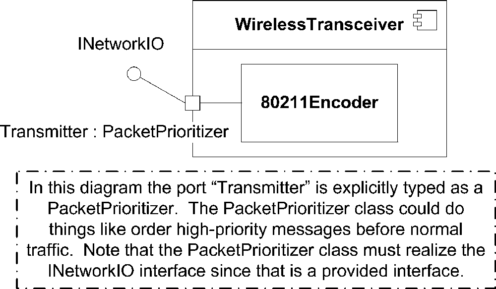
In practice, when a port is instantiated, it is represented by a classifier that realizes the provided interfaces. Any communication with this interaction point simply passes the information to internal classifiers that realize the behavior. UML 2.0 allows you to specify the type of a port using classes to provide more sophisticated behavior. For example, you can specify that the port is typed using a class that filters the communications it receives or prioritizes delivery. When this port is instantiated, the corresponding class has a chance to manipulate the communication it receives before passing it to the realizing classifiers. To show that a port should be represented using a specific classifier, simply follow the name of the port with a colon and the name of the classifier to use. Note that the classifier must realize the provided interfaces. You can use this notation to show provided interfaces by using an interface as the port type, though the lollipop notation is often more flexible. Figure 4-10 shows an explicitly typed port.
Structured Classes and Properties
As described in Chapter 3, classifiers with whole-part relationships typically use composition arrows to show their relationships. In the context of composite structures, UML 2.0 has defined the term property to describe the “part” piece of the whole-part relationship. For example, in a graphical operating system, an application may be made up of a main window and several buttons. The buttons are a part of the application, so that the whole-part relationship between the application and the buttons can be shown using composition. However, the main window is shared with the operating system (so the system can reposition the window or hide it); as a result, the operating-system-to-window relationship is slightly weaker and is shown using association. You can model the application, window, and button relationships as shown in Figure 4-11.
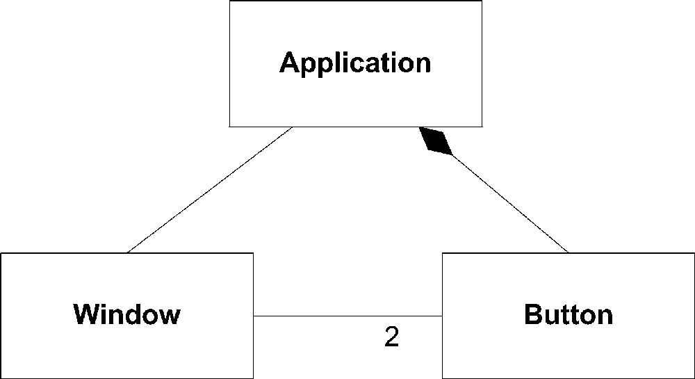
When used in composite structure diagrams, relationships between properties
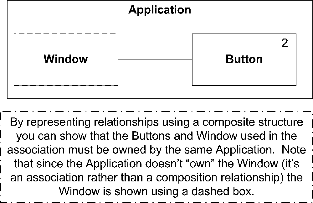
are shown in the owning classifier’s rectangle. This allows you to further restrict the association between parts of the composite classifier. For example, Figure 4-11 shows that Buttons can be associated with any Window. Using a composite structure diagram, you can restrict the Window to be associated only with a Button owned by the same application. When you draw the composite structure diagram, properties that are associated with the composite structure through composition are shown with solid rectangles, and properties that are shared with other structures are shown using a dashed rectangle. You may place multiplicity information for a property in its rectangle in the upper right corner, or after the name of the property in brackets. Figure 4-12 shows the composite structure diagram of application, window, and button relationships.
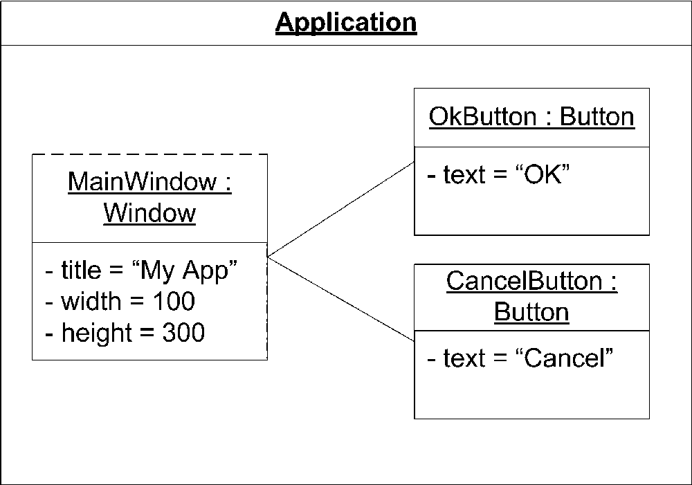
In addition to simply specifying how properties fit together, you can use composite structures to specify how instances are instantiated. As in Chapter 3, instances are shown by underlining the name and type of the classifier. You may specify initial values for each attribute of a classifier by specifying the name of the attribute followed by an equals sign and the value of the attribute. When used as instances, you can specify the roles each property will take on by showing a slash “/” followed by the role name after the property name and type. Figure 4-13 shows the initialization of a button with its appropriate values.
You can show that the instance of the owning classifier is related to a particular constructor of a classifier using a dependency line labeled with the keyword «create». You can use any parameters to the constructor when initializing properties simply by using the parameter name. Figure 4-14 shows the application composite diagram tied to a constructor on the Application class.

Collaborations
One of the primary purposes for composite structures is to document how a particular piece of functionality is implemented within a system. This organization of elements to realize behavior is called a collaboration . A collaboration is a collection of instances wired together using connectors to show the communication flow.
Because the purpose of collaborations is to describe how a particular piece of functionality works, details outside the scope of the desired functionality are typically left off a diagram. Instead, a collaboration diagram shows the required links between instances and the attributes involved in the collaboration. You may have multiple collaborations involving the same instances but showing different views of each based on the functionality expressed. One effective way of showing different views of a classifier is to use interfaces to collect related functionality. A single class may realize multiple interfaces, but each collaboration can focus on a single interface. See "Interfaces" in Chapter 2 for more information.
Within a collaboration, it is helpful to name the instances involved. You typically name an instance based on its role in the collaboration. For example, if you wish to model the Observer/Observable design pattern, you will likely have an instance in the role of Observer and an instance in the role of Subject.
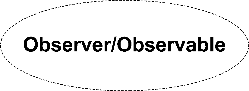
You show a collaboration using a dashed ellipse with the name of the collaboration written inside. Figure 4-15 shows a collaboration named “Observer/Observable.”
There are two ways to render the details of a collaboration. The first is to add a compartment to the collaboration ellipse and draw the instances involved in the collaboration inside. Links between instances are shown as solid lines. Each instance is named according to its role in the collaboration. Figure 4-16 shows the internal structure of the Observer/Observable collaboration.

Alternatively, you can show the instances that make up a collaboration outside of the collaboration ellipse and use communication links to tie them back in. In this case, you don’t specify the role name inside the classifiers; instead, you write the role name along the communication link for each instance. The advantage of this notation is that you can specify the attributes and operations that are involved in the collaboration (remember, you can leave off any attribute or operation that isn’t directly related to the functionality you are expressing). The disadvantage of this notation is that you don’t model the direct communication paths between the various instances. Figure 4-17 shows the Observer/Observable pattern using this alternate notation.

The UML specification makes it clear that any classifier can be substituted for any member of the collaboration as long as they provide the appropriate attributes and operations to fulfill their role. For example, in the Observer/Observable collaboration shown in Figure 4-17, the Observable must have a means of adding, removing, and notifying observers, and the Observer must have a way to handle changes to the observable. Any other classifier may be used in this collaboration as long as it can provide the message font attribute and the appropriate operation. As mentioned earlier, interfaces lend themselves nicely to collaborations. You can define an Observable interface and programmatically capture exactly what attributes and operations are needed to fulfill a role.
UML 2.0 makes collaborations full classifiers, meaning you can attach sequence diagrams, state machines, or any other behavioral diagram to help capture the details of the implementation.
Collaboration Occurrences
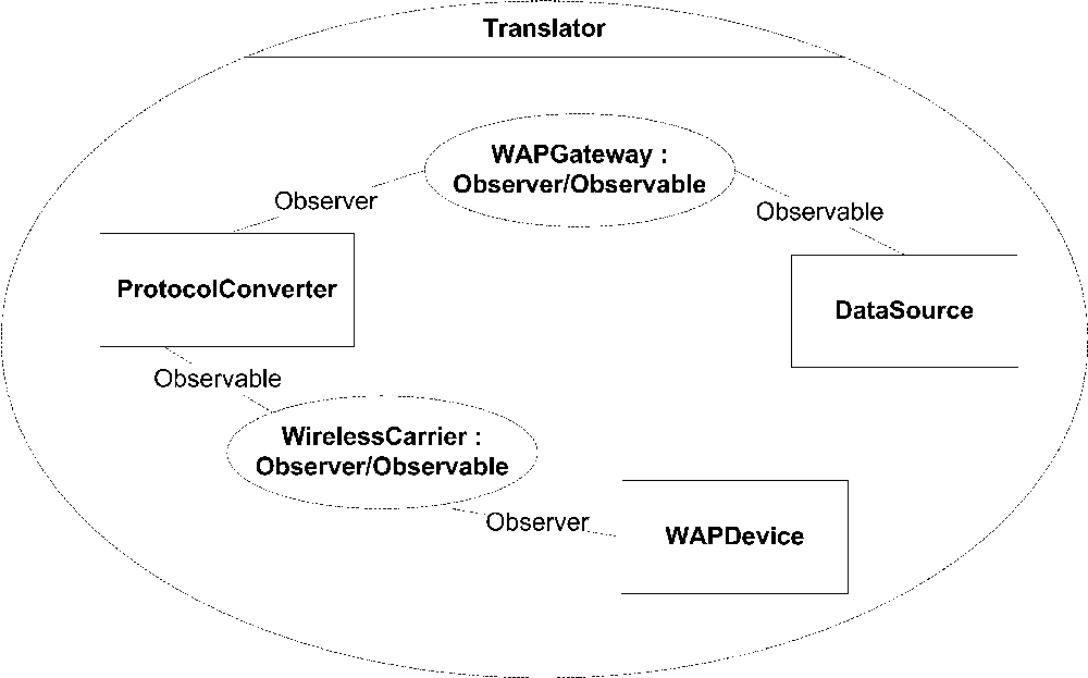
UML 2.0 introduced a new concept to allow you to attach a collaboration to a specific operation or classifier to show how it is realized by other elements. When you associate a collaboration with an operation or classifier, you create a collaboration occurrence . You can think of collaboration occurrences as instances of collaborations. For example, you can use a collaboration occurrence to document how various classes make up a subsystem, what is responsible for persistence, what is really a façade to another subsystem, etc. The advantage of using a collaboration occurrence to document the implementation of functionality is that you can assign role names to internal elements of the classifier. There may be multiple occurrences of a particular collaboration within a classifier, each with different internal elements fulfilling the roles of the collaboration.
You show a collaboration occurrence using the same dashed ellipse used to show a collaboration, except that you list the name of the occurrence followed by a colon, and then the name of the collaboration type. For each role used in the original collaboration, you draw a dashed line from the collaboration occurrence to the element fulfilling the role. You label the dashed line with the name of the role. For example, a collaboration occurrence of our Observer/Observable collaboration is shown in Figure 4-18.