
Once you’ve built your robot, you’re going to want it to go somewhere—and everyone knows the shortest distance between two places is a straight line. In the world of LEGO robots, going straight is one of those things that is easier said than done. Many new teams in FLL will rely on odometry, or dead-reckoning, to get their robot to the desired location on the game field.
Odometry is when you use measurements or rotations as a way to navigate your robot to a point on the field. You’re simply telling the robot to go a predefined distance, and using the rotation sensors built into your robot’s NXT motor to determine if you’ve gone the desired distance. The position will be measured relative to your starting point. As you will discover, this does not always land your robot where you expected it to end up.
Solely relying on odometry for navigation of your robot is not a good idea; a smart robot will find ways to incorporate landmarks on the game field and be able to analyze where it is in relation to its target using various methods and sensors. It is important to recognize the limitations of the technique, including its risks and to use it only when appropriate. In the FLL Smart Moves challenge, some field items were put in place to purposely limit the use of pure odometry in navigating the missions. So while it can be quick a way to get started on some missions, try not to rely on it too much.
Knowing the circumference of your drive wheels is important when determining how far your robot is going to travel, assuming you are running your wheel directly off the motor, and not going through a series of gears. If you program your Move block to turn four rotations, how far is your robot actually going to travel? This is where knowing your wheel’s circumference is important. So now you get to use some math. A basic formula to know is circumference = pi × diameter. The circumference is the distance the wheel will travel after one complete rotation, as seen in Figure 7-1.
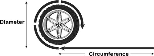
Figure 7-1. Calculating the circumference of a wheel
Note Pi refers to the standard mathematical value by which you multiply the diameter to obtain the circumference. Pi is a never-ending string of decimal digits, but 3.14 is a reasonable approximation.
If your wheel has a circumference of 3 inches and you’re moving four rotations, the expected result is that your robot is going to move forward 12 inches (circumference × rotations); or if you need to calculate the number of wheel rotations, then the formula would be duration = distance/circumference. This may seem very straightforward to understand, but so many teams skip right over doing such calculations and just use “trial and error” to get the correct value for their count of the wheel rotations. And then what happens is that something changes with their robot, such as gear ratios or wheel size, and now all their movements are miscalculated and they have to start over with a guessing process to determine the proper rotations.
But if a team understands the math behind calculating the proper rotations from the beginning, then changes will have a very minimal effect on their progress and will not delay the team in moving forward. Also, these are good talking points the team should share with an event’s robot design judges. Judges are much more impressed with teams that understand and explain why the robot is performing the way that it is. If a judge asked a team member why the team chose to use four rotations in their program, and the team member simply states that they “just kept trying numbers until something worked,” it doesn’t sound nearly as impressive as being able to explain the true mathematical reason why four is the correct number of rotations needed for the robot.
Don’t forget to take any gear ratios into account when calculating the proper rotation. The gear ratio is the value determined by the number of rotations one gear may have in relation to another gear that is driving it. For example, if a small gear is driving a larger gear, the small gear will turn more times than the larger gear. The small gear may turn three times for every single turn of the large gear. Such would be a 3 to 1 ratio, often expressed as 3:1.
In a scenario involving a gear ratio from a driving gear, you would determine the number of wheel rotations using the following formula:
duration = distance ÷ (circumference × ratio)
For example, say that you have a wheel with a circumference of 3 inches that is being driven by a motor hooked to a gear setup with a 3:1 ratio. Your formula would be:
rotation = 12 ÷ (3 × 1/3)
Do the math and you get 12 rotations to travel 12 inches, which is 1 inch per rotation. The multiplication by 1/3 in the formula accounts for the gear ratio, giving a result that you can work with in your motor programming.
Within NXT-G, there are two blocks you can use for moving your robot in a straight line: the Move block and the Motor block. The Reset Motor block is also helpful, providing a way to reset your rotation count between moves. Finally, you can take advantage of MyBlocks to group all the operations related to a given move by the robot. Doing so simplifies your program and lets you look at things from a more conceptual level.
The Move block (see Figure 7-2) in NXT-G would seem to be the obvious solution to programming a robot to travel forward straight, and in most cases this is true. The Move block allows you to control multiple motors at once, and it is designed to keep the rotation of the port B and port C motors in sync using an internal motor synchronization algorithm. This works well on most robot designs and shouldn’t be a problem.
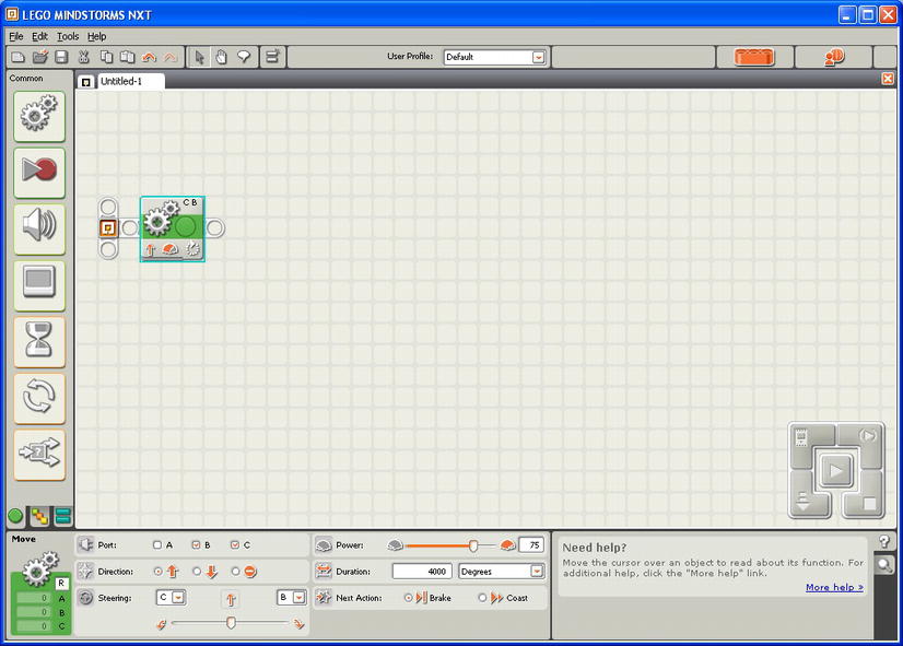
Figure 7-2. NXT-G Move block set to go straight for 4000 degrees
One of the things that is missing from the Move block is the ability to control the power ramping for the motors. For example, if you tell your robot to move forward eight rotations with a power setting of 70%, it will run at 70% power until it gets close to the end of the eighth rotation, then it will slow down to avoid overshooting its stopping point. With the Move block, you have no control over this ramping down, so if this is a problem for your desired effect, the Motor block would be a better choice for your program.
Caution Avoid putting a Move block within a repeating loop. Doing so can cause issues with the Move block maintaining a straight line due to the internal sync logic of the Move block.
The Motor block only allows you to control one motor per block, so to go straight, you would need to include two Motor blocks for each section of code that wishes to move the robot forward in a straight line. It will be important that you keep the two blocks in sync yourself.
For example, if you wish for the robot to travel 5000 degrees forward, you will have to set the distance units on both Motor blocks to be the same. You will also need to tell the first of the two Motor blocks not to wait for completion before running the next block. You do this by disabling the “Wait for Completion” check box. The second block will then need the “Wait for Completion” check box enabled, as seen in Figure 7-3.
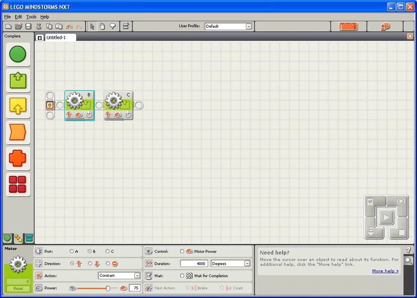
Figure 7-3. NXT-G Motor blocks set to go straight for 4000 degrees
Tip It’s a common mistake to omit disabling the “Wait for Completion” feature. If you see your robot spinning in a circle—one wheel turning while the other remains stationary—you may have fallen prey to the mistake. Look to see whether you’ve unchecked the “Wait for Completion” box.
Unlike the Move block, the Motor block will allow you to specify some ramping up or ramping down.
One of the more underused blocks is the Reset Motor block; executing this block is a great way to help your robot avoid getting confused when running multiple program segments. Executing the block for a motor will reset the motor’s automatic synchronization, which is used in blocks like the Move block.
It’s a good idea to reset the motors between moves. If your robot seems to get confused about how far it’s traveling after running various segments in your program, then using the Reset Motor block between these code segments is a great way to keep things running smoothly. Figure 7-4 illustrates this.
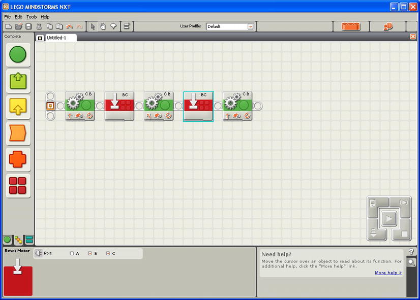
Figure 7-4. A series of move segments with a Reset Motor block between each
The code for moving often involves more than a single block. Using MyBlocks, you can combine all the logic for a given move or type of move into a single unit. You can give that unit a name that makes your code more readable. You can move units around in your code as you troubleshoot and improve your logic.
Consider the task of moving a specific distance in a straight line. One of the things discussed earlier was using the circumference of your robot’s wheels and the desired travel distance to figure out the number of rotations your motor needed to turn. To make life simpler, you could add that math into a MyMove block and have the NXT figure out the necessary rotations for you.
Figure 7-5 shows an example. You create three variables: Motor Power, Circumference, and Distance. Motor Power will feed directly into the MyMove block’s power wire. Circumference and Distance will feed into a Math block so that you can divide the Distance value by the Circumference to get the necessary rotations for the motor to reach your destination.
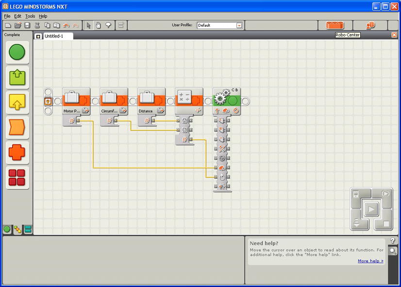
Figure 7-5. Creating the MyMove block
Now that you have your code, you can create the MyMove block. When creating a MyBlock that has parameters, you need to be careful when selecting the code that will be included in the actual MyBlock. Leave the variables that will be the parameters out of the selection, as seen in Figure 7-6.
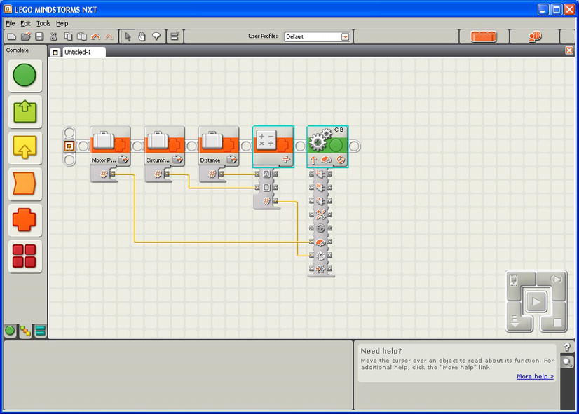
Figure 7-6. Highlighting just the Math and Move blocks—the variables are left out so that they become parameters for your MyMove block
Now that you have the Math and Move blocks selected, you can create the MyMove MyBlock. Figure 7-7 shows that when you created the MyMove block, you ended up with three crosshatch (#) symbols on the left. These represent the three variables that you’re using for inputs. They will now show as parameters for the MyMove block, as seen in Figure 7-8.
It is a good idea to rename the parameters to logic value names so that you will know which values are expected and so that other people who use your block will also understand the values to enter. The default A and B labels don’t give a good clue as to which values are expected. Giving the MyBlock a unique icon also helps the user recognize the block visually.
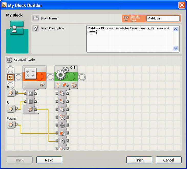
Figure 7-7. The new code that will be included in the MyMove block, including three input parameters
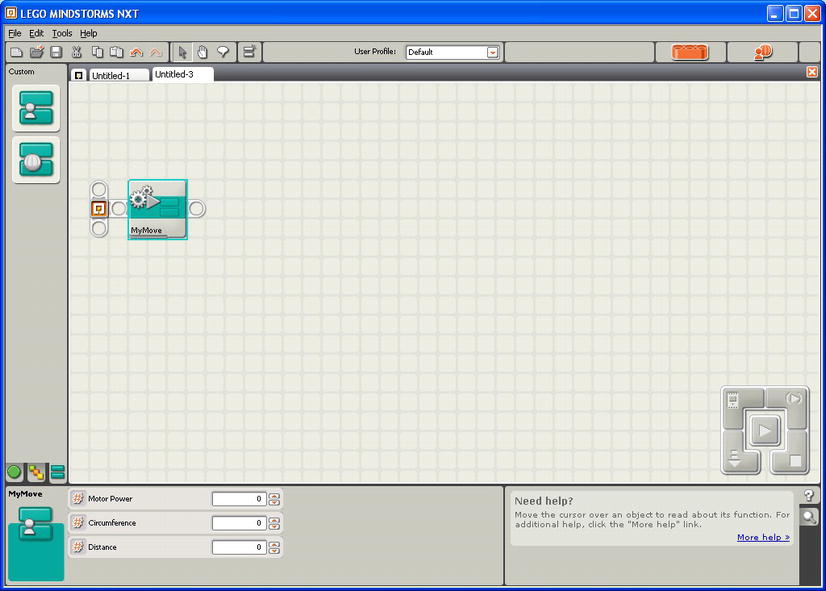
Figure 7-8. The MyMove block now has three input parameters: Motor Power, Circumference, and Distance
So now you have a reusable MyMove block that can be used in place of a Move block. And the nice thing is that it will calculate the number of rotations needed based on the information you provide to it.
You can build on this and make a MyMove block just for your one particular robot, and then you can hard-code the circumference of your robot’s wheels into the MyMove block, and only have to enter the Distance and Motor Power when using the MyMove block. The nice thing about this is that if you changed the wheels on your robot, you’d only have to make the change to the circumference value in your MyMove block to match your new wheel size, and all the programs that use this block would change accordingly. Very simple with no mess.
Not only do you need your robot to go straight, but it will need to turn as well. There are various techniques to make your robot turn, as well as different NXT-G blocks that you can use to get it moving in the direction that you want.
You learned about the Move block when you wanted to go straight. Now that you want to turn, the Move block can be used again. The Move block has a steering parameter that allows for values between -100 and 100. There is a slider on the block that can move ten positions to the right and ten positions to the left. Each position represents increments of ten. If you wish to enter a value that is not an increment of ten, then you can simply pass it in via the wired parameter.
Table 7-1 presents the key values that are helpful with using the Move block for steering.
Table 7-1. Move Block Common Steering Settings
| Steering Value | Steering Results |
|---|---|
| 100 | Pivot to the right |
| 50 | Turn on one motor to the right |
| 0 | Go straight |
| −50 | Turn on one motor to the left |
| 100 | Pivot to the left |
Other steering values are allowed and can be useful when wanting to travel in a large arc, but they require a bit more trial and error when using the Move block.
Using the Motor blocks for making turns can result in turns that are more predictable, but at the same time, teams new to NXT-G sometimes get confused by switching between Move blocks and Motor blocks. So if you’re more comfortable with only using the Move blocks, then do what works best for you and your team.
With the Motor blocks, you find that you have more control over your turns simply because you specify the actual power, direction, and duration of each motor. As you saw earlier in this chapter, it’s nice to have control over each motor when calculating the durations for your various types of turns.
One trick is to remember that Motor blocks need to be run in sequence, either by branching off a second sequence beam (see Figure 7-9) or by setting the first Motor block in the sequence with the “Wait for Completion” feature turned off (see Figure 7-10).
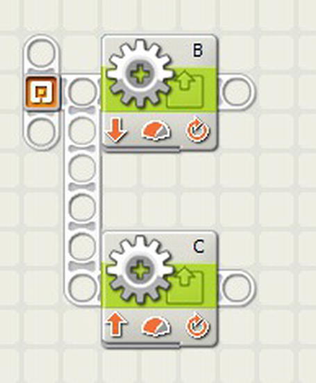
Figure 7-9. Motor blocks on different sequence beams
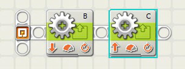
Figure 7-10. Motor blocks on the same sequence beam
Also be aware that one Motor block may complete before the other, so you will need to let both motor blocks finish before your code moves on to the next statement. Simply adding a slight delay after your move can compensate for this 90% of the time. If you need something more complex, you can simply add some logic that confirms that both Motor blocks have completed their movements before advancing to the next statement in your program.
In Figure 7-11, you can see that each motor will run until competition, then sets the Logic blocks after them to True. The Loop block on the main sequence beam will continue checking both Variable blocks, and loops until both are True. This way, the program knows that both Motor blocks have stopped running.
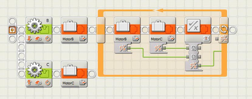
Figure 7-11. Logic added to verify that both Motor blocks have completed running before the program continues executing
Most LEGO robots use differential steering, which is where the robot controls its turning direction by using two motors, each mounted on either side of the robot. This is the way bulldozers, tanks, and even wheelchairs turn. There are two different ways to turn a differential steering robot—either by turning both wheels or by only turning one wheel and pivoting on the stationary wheel. The trick is to figure out how much you should turn the wheel to get the desired turning position.
Using the upcoming calculations, you will able to accurately calculate the degrees needed for precision turning. Remember though, LEGO robots are based on toys and are not nearly as precise as larger, more expensive robots. So no matter how accurate your math is, the LEGO robots will still need some final tweaking.
Note There is about 6 to 8 degrees of gear slack—free movement between gears—in a LEGO NXT motor, so getting accurate movements within a few degrees is not possible. Always allow some room for error when turning.
If you are turning your robot to the left by only turning the right wheel forward and keeping the left wheel stationary, this will create a steering circle with the left wheel’s position as the center (pivot point). The distance between the right and left wheel, called the track, will be the radius of the steering circle, as seen in Figure 7-12.

Figure 7-12. Robot making a 180-degree turn with a single motor
The circumference of the steering circle is calculated using the following formula:
circumference = 2 × radius × pi
So to turn 90 degrees, your robot would have to travel one quarter of the circumference of the steering circle; whereas a 180-degree turn would require traveling half the steering circle circumference. To calculate the duration needed to use in your Motor block, you would first determine the distance you need to travel around your steering circle. So if you’re turning 360 degrees (the complete circle) with your robot, which has a track of 5 inches, the formula would be something like this:
distance = steering circle circumference
distance = 2 × 5 × 3.14
distance = 31.4 inches
With the distance now known, you can calculate the duration needed in your Motor block by using the same formula that you used to calculate the duration when going straight. So if your robot has wheels that have a diameter of 3.25 inches, the formula will look as follows:
duration = distance/wheel circumference
duration = 31.4 ÷ (3.25 × 3.14)
duration = 2.86 rotations
or
duration = 1029.6 degrees (2.86 × 360)
Now you have found that the number 2.86 is the key. You can multiply this number by any angle turn you wish to make. So if you want your robot to turn 90 degrees instead of 360 degrees, you simply calculate the duration by using your newfound 2.86 key. The duration of a 90-degree turn is calculated as follows:
duration = 2.86 × 90
duration = 257.4 degrees
Even though your key value is unitless, when making these calculations, remember that you keep the units the same for your other values; so if you’re measuring your track in inches, the resulting distance will also be in inches. This is the same for the wheel diameter: if all of your other measurements are in inches, then you need to measure the wheel in inches as well.
With the single-wheel turn, your robot is only powering one wheel and turns the robot around an arc. But if you turn both wheels in opposite directions, you can then pivot the robot right where it is sitting. The pivot point is no longer the stationary wheel but the center of the robot’s track. You can even use the same calculations used to determine the number of degrees to make the turn in the same way that you did with the single-wheel turn. The only difference is that you will have to divide the degrees in half and apply them to both wheels; one wheel will move in the opposite direction of the other. Figure 7-13 shows how the steering circle is much smaller than the steering circle of a single-wheel turn—actually half the size.

Figure 7-13. A robot making a 180-degree pivot turn with both motors would create a steering circle with the diameter being that of the robot’s track. The center of the steering circle would be the center point of the robot track
So let’s say you want to pivot your robot 180 degrees. Then you would again use the key value that you calculated earlier—2.86—and multiply it by 180, and then divide by 2. You need to divide by 2 since the pivot point is in the middle of the track. Both motors will assist in the turning, so they each only need half as much turning to get the desired duration; for example:
pivot duration = (2.86 × 180) ÷ 2
pivot duration = 514.8 ÷ 2
pivot duration = 257.4 degrees
If we are using a Move block, you set the steering to 100 or -100, depending on which direction you wish to turn, and then enter a duration of 257.4 degrees, as seen in Figure 7-14. You can also use a pair of Motor blocks—one for motor B and one for motor C. Simply set the duration for both Motor blocks to 257.4 degrees, and then set one Motor block to travel in the opposite direction of the other Motor block. Be sure to either put the block in parallel, or set the first block to not wait for completion, or else the NXT will run the first Motor block and then run the second one, giving you a completely different turn result than you expected (see Figure 7-15).
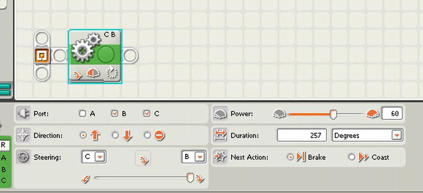
Figure 7-14. A Move block being set to pivot the robot 180-degrees by using a value of 257.4 as the Duration, and the steering set all the way to the far right

Figure 7-15. Two Motor blocks being set to pivot the robot 180 degrees by using a value of 257.4 as the Duration, and the two blocks turned in opposite directions
Both the Move and Motor blocks work equally well for pivoting. I have always preferred the pairing of the two Motor blocks versus using the Move block—just as a personal preference.
Creating a Custom MyPivot Block
While doing all the calculations for the duration needed to turn in the direction we desire, you may have realized that much of that logic could be included in a custom MyBlock to be used for making a pivot turn. Let’s call that new block MyPivot. For example, once you know the key value (2.86 for the robot we just calculated), you could make it a constant in your new MyPivot block, where all you need to do is enter the desired turning degrees and let the block calculate the true duration needed for your robot to complete the turn.
If your robot’s wheels or track size change in the future, we simply recalculate the key value and modify the key constant in your MyPivot block without needing to modify any of your code elsewhere. In Figure 7-16, you can see the code that will make up your new MyPivot block. You have a Variable block for your degrees, and a Constant block that will hold your key value of 2.86. These values are then passed to the Math block, where they are multiplied by each other and passed to one more Math block so that you can divide them by 2. The new calculated duration is then passed to a pair of Motor blocks that are running in the opposite direction of each other.
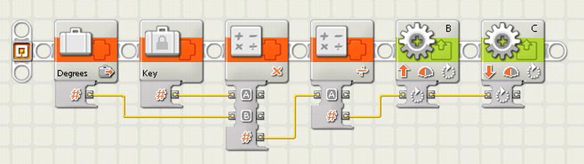
Figure 7-16. The definition of MyPivot block, which allows the user to pass in the desired turn degrees and have the duration calculated automatically
To create your new MyPivot block, you will select all the blocks in your code except the Degrees variable, which you purposely leave out of your selection (you’ll see why in a moment). Once we have the blocks selected, as seen in Figure 7-17, go to the Edit menu and select “Make a New My Block”. Next you will see the My Block Builder dialog box displaying the code that you selected. Now notice that since you did not select the Variable block that contained your degrees value, a special parameter wire was added to your new block. Currently, it is labeled with the letter B, but you can change that later. Figure 7-18 shows the newly created MyPivot block being used with Degrees as the single parameter.
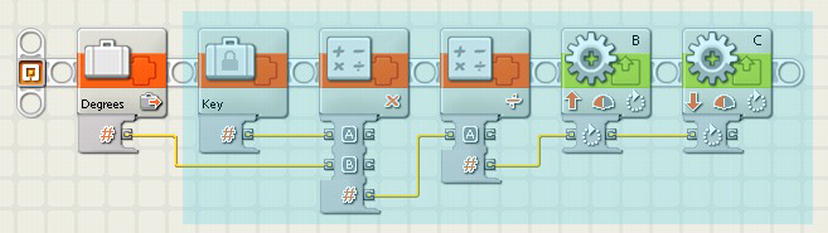
Figure 7-17. Selected blocks that will be a part of your new MyPivot block
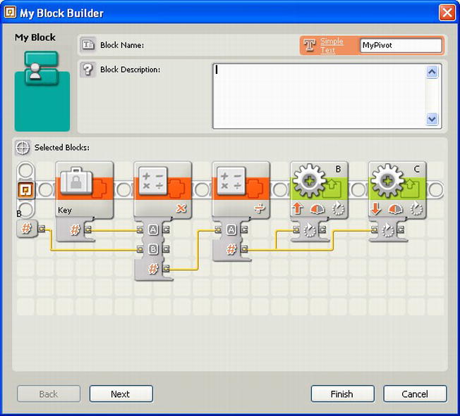
Figure 7-18. The My Block Builder with your code blocks for the MyPivot block. The wired parameter labeled “B” will be your input of degrees
Now when you’re done in the My Block Builder dialog box, your newly created MyPivot block will be inserted into your code to replace the code that you selected to be part of the block, as seen in Figure 7-19. The MyPivot block in this example will turn the robot counterclockwise; you can make two versions and change the direction of the two Motor blocks to run in opposite directions. You’ll also notice that when you select the MyPivot block, you are presented with one single parameter labeled “B”. This parameter is the degrees that we want your robot to pivot.

Figure 7-19. Here you can see the new MyPivot block connected to the Variable block that we left out of the MyPivot definition
We could just leave the label set to the letter B as long as we remember what the parameter expects, but to make the best use of your new MyPivot block, we should add the proper label for your own reusability and anyone else on the team that may want to use the MyPivot block.
To change the label, you simply select the MyPivot block and then either double-click the block or select the Edit menu and choose “Edit Selected My Block”. The My Block Builder dialog box will open, showing you the code blocks contained within your MyPivot block. If you click on the B label for the input parameter, you can simply type any new label you wish for the parameter; in your case, we’ll rename the parameter Degrees, as seen in Figure 7-20.

Figure 7-20. Changing the label on the input parameter to read “Degrees” instead of the letter B
Now whenever you use the MyPivot block, the parameter displays as Degrees and makes much more sense to whoever is using the MyPivot block. This helps make the code self-documenting. You can see the results in Figure 7-21.
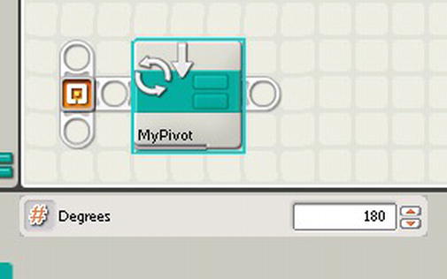
Figure 7-21. The final MyPivot block with the input parameter properly labeled for easy use and readability
Creating a Custom MyTurn Block
Let’s say that you want a block to do single-wheel turns. You can simply modify the MyPivot block by removing one of the Motor blocks and removing the Math block that divided the calculated value by 2. It would look like what we see in Figure 7-22.
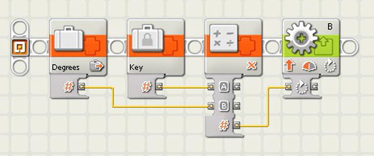
Figure 7-22. The MyTurn block: similar to the MyPivot block but with only one Motor block and a single Math block
Now if the Move block is more your style for steering but you’d like to have more flexibility with the steering parameter, you could create a MyMoveSteering block that accepts a parameter value between 100 and -100, thus giving you more control of the steering versus the slider that currently exists in the Move block.
There are times when you need to run a motor but don’t exactly know the distance or duration to run the motor. When you’re using a motor to operate a claw attachment, for example, the objects that you’re grabbing may vary in size, so sometimes the motor needs to run longer than it does at other times.
If you set the Duration on a Motor block to turn for 90 degrees but the NXT motor is blocked from turning a full 90 degrees, the next block in the sequence will never be executed since the Motor block was not able to complete its action.
A smart solution to this is stall detection, which is when your code checks the rotation values of the motor and calculates if the motor is still turning or if it has stopped (or is blocked).
- Start the motor moving.
- Take a reading of the motor’s position (PosA).
- Wait a very short time interval.
- Take a second reading of the motor’s position (PosB).
- Subtract the PosA value from PosB.
- If the difference is less than 5 degrees, then the motor has stopped turning.
The flowchart diagram in Figure 7-23 shows logic of the stall calculation.
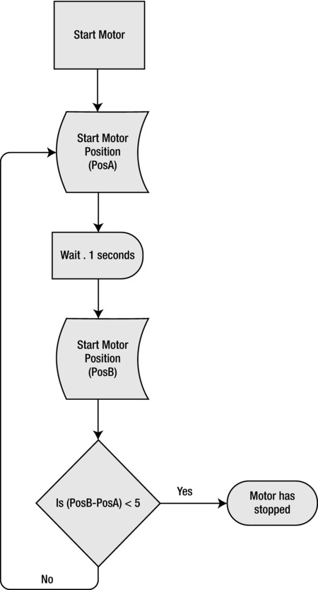
Figure 7-23. Flowchart diagram of the motor stall logic
You can follow the logic in Figure 7-23 by writing a Move block followed by a Loop block that would encapsulate the stall detection logic. Within the loop, monitor the rotation value of the motor. Take a reading. Wait before taking a second reading. Evaluate using a Compare block within a Math block to see whether the rotation varies by more than just a few degrees—say five degrees. If the rotation difference is less than your threshold, then assume that a stall has occurred. Return a value of True to indicate a stall, and False otherwise.
Figure 7-24 shows an example of how to program the stall-detection logic laid out in Figure 7-23.
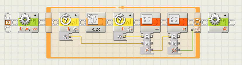
Figure 7-24. Motor stall detection program
Summary
Making your robot perform an action will more than likely involve one or more motors. It is important for you to understand how to make the motor do what you want it to do successfully. Taking some time up front to calculate the proper values for your motor’s motion will save you a lot of work later in the design and debug process.
The concepts discussed in this chapter can seem a bit overwhelming, but once you fully understand how to make use of these ideas, you will find that approaching new missions and tasks becomes easier. Don’t let the math overwhelm you and just practice the concepts until they make sense.