
A robot that can detect and interpret its surroundings and then make decisions based on those findings is a smart robot. A smart robot is the key to a winning robot. One way for your LEGO MINDSTORMS robot to acquire input from its environment is to use an NXT Light sensor. Many new teams are intimidated to use sensors other than the rotation sensors built into the NXT servos. This doesn’t need to be the case.
One of the great things about the NXT Light sensor is that it’s a passive sensor as far as hardware. You simply place it on your robot (facing the direction you wish to use for detection) and wire it up. It is ready for action. In order to get the most out of it, you will need to have a good understanding of how the sensor works and what you’ll use it for. The ability to develop smart programming code to interrupt the input received from the NXT Light sensor is also important. With that said, our first task in this chapter is to go over just what the Light sensor is and how it works.
The NXT Light sensor allows your robot to visually analyze its environment, basically giving your robot the gift of “sight.” Your robot will be able to detect the differences between light and dark, either by detecting the ambient light of its surroundings or by analyzing the color of something in front of the sensor.
Note The LEGO MINDSTORMS Education NXT Base Set (9797) includes one NXT Light sensor. The LEGO MINDSTORMS 2.0 retail set no longer includes the NXT Light sensor but instead has an NXT Color sensor. Currently, FLL rules allow for multiple Light sensors, either the regular or the Color sensors. Be sure to check the rules each year since they are subject to change. Note that only LEGO brand Light sensors are allowed at most LEGO robotics events. There are a few off-brand Light sensors available for the LEGO MINDSTORMS NXT, but these are not allowed in many LEGO robotics events.
The NXT Light sensor contains an LED and a phototransistor that reads the reflected light from the LED or the ambient light in the room. Ideally, the Light sensor will read from a very narrow field of vision. This field is based on the distance of the sensor from the light source. Pointing the Light sensor at the light fixture on your ceiling gives you a very high-level reading. If you held a black LEGO brick between you and the ceiling light, the sensor would not recognized the brick simply because the field of vision was too great. But if you placed the brick on a table, and pointed and held the Light sensor just a few inches over the brick, it would be able to detect the dark-colored brick. Keep this in mind when placing your Light sensor on your robot’s chassis.
Figure 8-1 compares a Light sensor’s field of vision when held both close to and far from the LEGO brick. When the sensor is close to the brick, the brick fills the sensor’s field of vision. The brick’s black color predominates. The Light sensor will return a value indicating darkness.
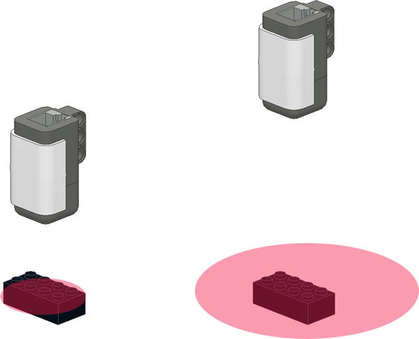
Figure 8-1. The closer the Light sensor is to an object, the easier it is for the Light sensor to detect the object’s light value
Pull the sensor back, however, and the brick becomes just a small object in a wider field of vision. If the background is light enough, the sensor will not detect the small dark brick against the much lighter background. Detection of the dark brick is more reliable when the field of vision is narrow.
The Light sensor can measure ambient light when the “Generate light” option is not turned on in the Light sensor block (see Figure 8-2).
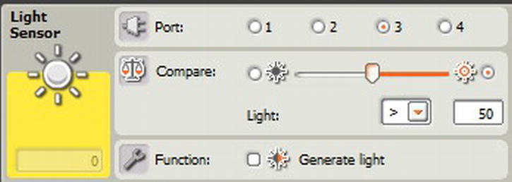
Figure 8-2. Light sensor properties with the “Generate light” option turned off
This option turns off the sensor’s LED, allowing the light in the room to be the sensor’s main source. If you have a robot that needs to detect a dark or bright room, or maybe to determine if it’s daytime or night, these types of applications are useful in measuring ambient light. This kind of measurement is rarely necessary or useful in a LEGO robotics event, however. During most robotic competitions, the robot is trying to detect markings on the game field, and not really concerned about the room’s lighting.
We will use the Light sensor for reading reflected light levels—the intensity returned from the surface that the LED light reflects. When properly calibrated, the intensity levels will range from 0 to 100, but when you look at the noncalibrated values of the Light sensor, you will see that the range is much smaller, more like 30 to 70. This is because the Light sensor can read a much wider spectrum of colors beyond what our human eye can see. So the calibration process puts the values into a range that you can find useful.
When using the Light sensor as an input source, you learn quickly that ambient (or background) light varies from place to place. The light in your classroom or basement may be quite different from the light where a robotics event is being held. So the idea behind calibration is to adjust your sensor to the conditions expected in the room.
Depending on the room, you may only need to calibrate once in the room that you run your robot, even if you are running it multiple times within the same day. But if the room has lighting conditions that change, such as large windows that bring in natural sunlight, you may want to calibrate your NXT Light sensors before every run. Proper shielding of your Light sensors is also important for getting consistent light-sensor readings. Anything you can do with your robot design to prevent outside light from interfering with your sensors is helpful.
Don’t start calibrating your sensors until you have them positioned on your robot’s chassis. Changing the sensors’ locations on the chassis can affect the value readings. Ideally, you’re going to want to keep your NXT Light sensors close to the game field; around 2 to 3 centimeters is a safe distance. But make sure your robot can clear any obstacles that it may have to climb. You don’t want your robot getting caught on the sensor because of low ground clearance.
You need to calibrate your sensor so that you can set the real-world values for lightness and darkness. In the ideal environment, the NXT believes white to be the maximum value returned and black to be the minimum value returned. These values are represented in the NXT-G code as values between 0 and 100, but rarely will an uncalibrated sensor ever return these values—most of the time the real values return within a range of 30 to 70. By calibrating the NXT, we are resetting the limits of the light reading range based on light readings in the current environment. Also, calibrating the Light sensor allows the robot to run in different environments without having to change the program code to contain the new room’s light values.
LIGHTING AT EVENTS
One year I was at an FLL qualifier held in an airplane hangar. The location was great, but the lighting was horrible for robots. Every game table in the room had different lighting contrast. This was an excellent opportunity to have a robot that would calibrate its light on each run. Too bad our team didn’t have such a calibration plan at the time. We got lucky and had a very good run on a table with consistent lighting. Our other runs that day were not as impressive.
Look out for rooms that have lots of natural sunlight coming through windows. I’ve seen events where the sun in the room changed throughout the day, and robots that ran flawlessly early in the day had issues as the lighting changed.
You can perform the calibration in two ways: by using NXT-G’s own Light Calibration block that stores the calibrated values in the NXT’s memory or by creating your own calibration program that stores the values locally in a file on the NXT.
In the NXT-G Advanced Tools menu, there is a Calibration block that is used to calibrate the maximum and minimum levels for both the NXT Light and Sound sensors. The values read by the Calibration block are stored on the NXT brick and remain until they are deleted or the sensors are recalibrated, even if the NXT brick has been turned off.
If you are using two NXT Light sensors on your robot, the calibration values stored by the Calibration block will be applied to both sensors. The NXT does not store separate values for each sensor.
To use the Calibration block, you simply add it to your NXT-G program. Most likely it is in a separate calibration program or at the beginning of the program that you are about to run. If you wish to include it in all of your programs and calibrate before each run, creating a MyBlock with your calibration code is a good idea. Be sure to verify with your event coordinator about when and where calibration is allowed.
You could create a My Calibration block, for example. Within this block, you would have to include two Calibration blocks—one to read the minimum light value and one to read the maximum light value—and some kind of trigger event, such as a Wait block, between the two Calibration blocks. For example, the first Calibration block reads the maximum light value, waits for the NXT orange button to be pressed, and then reads the minimum light value. When you first run this program, you hold the robot’s Light sensor over the lightest surface on the game field, preferably a part of the mat that is white (or a very light color). Next, you move the robot’s Light sensor over a dark area of the mat in order to read the minimum value. Then, you press the orange button on the NXT brick (see Figure 8-4). Figure 8-3 is a simple example of such a calibration program. You might want to elaborate on it by adding display prompts to let the user know where he should place the robot’s Light sensor and what to do next.

Figure 8-3. A simple NXT-G calibration program
If you attach your NXT brick to your computer via a USB cable or Bluetooth, and then select Calibrate Sensors from the Tools menu in the NXT programming software, you are prompted by a dialog box to download an NXT-G calibration program. This program works very similarly to the one described earlier and it already has all the prompts in place for easy use.
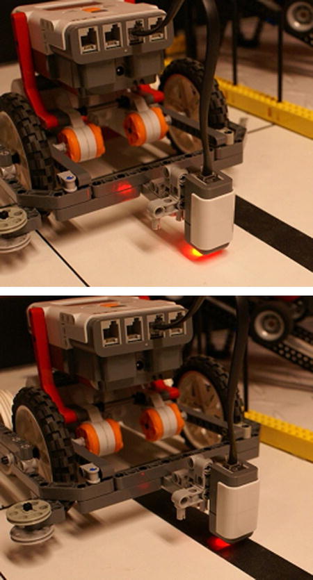
Figure 8-4. Calibrating the Light sensor over a light-colored area and a black line
You may not wish to use the Calibration block that comes with NXT-G. Your robot may have two Light sensors, for example, and you want to store a separate calibration value for each sensor. You can do this by creating your own calibration program and then storing the values in a text file on the NXT brick. By saving to a file, you are able to read that file and retrieve the stored light calibration values each time your programs are run.
The process I’ve described is really not as complicated as it sounds. It can be made into a really nice program without much effort or code. In Figure 8-5, you can see that the Calibration block is replaced with a Light sensor block that copies a value from the Intensity into a text file. If you are using multiple Light sensors, you could do the same process for each sensor, thus allowing you to have a unique light range for each. When using the NXT-G Calibration block, the value calibrated is applied to all Light sensors connected to the NXT brick.

Figure 8-5. An NXT-G calibration program that writes the max and min values to a text file
To use the values that you saved, your line-following program would first read the saved values in the files, and then calculate the desired light value range. This would require a bit more math for a Conditional line-following program, but would fit right into our Proportional line follower that is covered next.
One thing that confuses people about calibration is the newly calibrated values. The NXT has a built-in utility that allows you to view the values of its various sensors; but the NXT always displays the uncalibrated values of the Light sensor. So if you use the Calibration block and store new calibration values for the NXT Light sensor in the NXT’s memory, and then try out the built-in Light sensor viewer on the NXT, it will not show you the newly calibrated values, it continues to display the original uncalibrated values.
To work around this problem and be able to see the real values, we write our own Light sensor value viewer that will show us the calibrated values being returned from our Light sensor. It’s important for us to know these values so that when we start writing our line-following routines, we know the proper range values that our robot will be attempting to detect.
The program is simple, as you can see in Figure 8-6. You create a loop that contains a Light sensor block and that is wired to a Number to Text block. This converts the numeric value returned from your Light sensor to text so that it displays on your NXT screen. The converted value is now passed to the Display block. Wait a moment before taking another Light sensor reading.
A program like this is very helpful in figuring the initial range for your line-following program, when you’re debugging your program, and for experimenting with different Light sensor positions on your robot’s chassis. You can move the Light sensor around to get a feel for the difference in light readings based on things such as distance from the game field or even various light sources in your room.
You may find it helpful to run a viewing program while shining various light sources at your robot as it sits on the game field. You can discover how different kinds of light have an effect on your readings. Try the lights at various angles (shadows often cause more issues that the light itself).
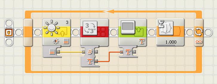
Figure 8-6. A calibrated light value viewer to display the calibrated Light sensor value on the NXT screen
The NXT-G Calibration block has a delete function that clears out any calibrations currently stored in the NXT brick’s memory. It is wise to clear out such values at the beginning of your calibration process—just so you know you’re working with clean values in your NXT brick, especially if you’re in a classroom where different people are sharing an NXT brick.
Figure 8-7 illustrates a basic Calibration deletion program. First, the program waits for the user to press the orange NXT button, then it deletes the current calibration with the Calibration block, and then it plays a confirmation tone.

Figure 8-7. A program to delete the current Light sensor calibration
A great way to navigate along the field is to follow any lines that may be present on the field map. In FLL, for example, the 2009 Smart Moves field was a line follower’s dream. There were nice thick black lines that could guide a robot to most of the important places on the field. Actually, it was done to encourage teams to incorporate line following, or at least line detection, in their robot’s logic.
A lot of teams recognize this but struggle with how to build and develop a good line-following robot. The code doesn’t have to be scary. Yes, you can have some very complicated line-following logic and use lots of fancy algorithms to keep your robot traveling smoothly, but at the same time, there are simple solutions. There are multiple techniques available for getting your robot to follow a line. Remember, though, that the techniques described in this section are just examples. You and your team are encouraged to use them as a starting point, but then build on the techniques and see how much better you can make them.
The simplest of line-following programs is a dual-state program in which the Light sensor either sees black or white, and adjusts accordingly. The robot oscillates back and forth over the line, constantly checking for either black or white values; even if the line is straight, the robot will continue to move back and forth searching for the line. The robot is looking for two conditions—the light value is either dark or is bright—and based on these values, the robot will go either to the right or to the left. So the robot is only working in a mode with two conditions (dark or bright) and two actions (turn left or turn right).
This kind of program is a good start for teams just learning line following and trying to get a grasp on the robot and the code. Most advanced teams use something a bit more complex, or at least smoother running. The more the robot oscillates, the slower it performs, so ideally the robot will run as straight as possible when navigating a line.
The code for such logic is fairly simple, as seen in Figure 8-8. The assumption is that your robot is only using one NXT Light sensor at this point. The example in Figure 8-6 shows a master loop that runs continuously. In a real-world situation, you would need to include some kind of condition that breaks the robot out of the loop in order to continue to the next step in the competition. But for this example, having the robot stay in a constant line-following mode is fine.

Figure 8-8. A simple line-following program that zigzags back and forth over the line
You will have a Switch block that is using a Control type of sensor. The sensor will be your Light sensor. You will also need to configure the port that the Light sensor is connected to on your robot. In Figure 8-8’s example, the Light sensor is connected to port 3.
Assuming that the robot’s Light sensor has been calibrated at this point, your Compare value for the Switch block will use 50 as the middle point. So if the light value returned is less than 50 (darker), you will turn the robot to the left—looking for a value that is greater than 50 (lighter). You can see that the power settings on the Motor blocks differ depending on which direction you wish to turn. In Figure 8-8, the motor’s power settings are 50 for the higher value and 20 for the lower. Depending on your robot’s design, you may need to adjust these values so that your robot doesn’t turn too sharply. Then you’ll loop back and check the Light sensor value again. There is no condition that allows your robot to move perfectly straight. It will always go to the left or the right as it moves forward.
This program is not following the line itself so much as the edge of the line. It tries to stay on the left edge of the line. If our line has lots of arcs to the right, you might want to switch up the program and follow the right edge of the line instead since any sudden changes in the direction of the line could cause this simple program to miss the line and end up in never-never land. This type of program works best with lines that stay relatively straight or only curve slightly. Lines with intersections are more difficult to detect with such a simple technique—they require a more complex solution, as described next.
With the Simple State example, the program only had two conditions: a light value either greater than or less than 50. The problem is that the robot tends to overcompensate for changes in the light value. Think of a car that has a tire go off the roadway. If the driver turns the wheel drastically to the left, he will bring the car back onto the road—but he could very well cause the car to lose control and run off the other side of the road. So the driver gradually turns the car back toward the road. He remains in control of the car since the compensative reaction was in relation to the amount of error needing correction.
You can do the same thing with your LEGO robots by adding more conditions to the switch logic. The value returned from a calibrated Light sensor is between 0 and 100. If the value is close to 0, we want to make a more drastic change in direction compared to a value around 35, where we’d only need a slight correction in direction. So we divide our possible light range (0–100) into smaller sections. Create five series of smaller ranges by dividing 100 by 20. This gives us the new condition values that we will use in our Switch block. Table 8-1 presents the code that we use for each condition in our code.
Table 8-1. Complex State Conditions
| Range Value | Action |
|---|---|
| 0 | Sharp Turn to the Left: slow down motor B. |
| 1 | Slight Turn to the Left: slow down motor B slightly. |
| 2 | Stay Straight: keep both motors equal. |
| 3 | Slight Turn to the Right: slow down motor C slightly. |
| 4 | Sharp Turn to the Right: slow down motor C. |
The example code seen in Figure 8-9 contains a master loop that runs continuously with a Light sensor block. The Intensity value from the Light sensor block is wired to a Math block in which we divide the Intensity value by 20 and the result is rounded off to the closest value. This value is what we pass to the Switch block. Since it is possible to get a return value of 5, when the light value is higher than 90, simply set your condition 4 as the default condition on the Switch block—thus forcing the condition 5 to use the same actions as the condition 4.
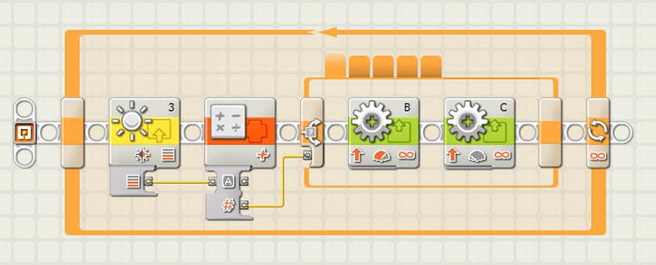
Figure 8-9. Complex condition line-following program with five conditions in the Switch block
Within each condition of the Switch block, the Move blocks are set at various power levels to force the robot to turn in one direction or the other; but when the condition value is 2, both Motor blocks are set to the same power level to allow the robot to travel straight.
To make the turns even smoother, take the Complex state method and further break down the Light sensor Intensity value from five conditional states to ten. This may be a bit much to manage in NXT-G. Large Switch blocks can become very clumsy in the NXT-G interface.
Whenever you talk to anyone about robotics and line following, the term “PID” comes up. It stands for proportional-integral-derivative. Most LEGO NXT-G programs that people claim are PID are really just P. For NXT-G, a proportional type of program is very doable, whereas a full PID is a bit much for such a simple programming language. A proportional system uses a bit of math to calculate the amount of correction needed to return the robot back to the line that it is following. So instead of using a set value to correct the robot’s direction, we calculate the direction change based on the value read by the Light sensor. If the error value is small, then the robot corrects very slightly; if the error is large, the robot must heavily correct.
For our example Proportional NXT-G program, we start with a few Variable blocks, as described in Table 8-2.
Table 8-2. Variable Definitions Used in the Proportional Line-Following Program
| Variable | Description |
|---|---|
| MidRange | The mid value between the minimum and maximum light readings. If the Light sensor is calibrated with a minimum value of 0 and a maximum of 100, the MidRange is 50. |
| Gain | Used to fine-tune our error correction. If the robot is zigzagging too much, set the Gain to a value lower than 1. If the robot is not responding fast enough, set the Gain a bit higher to adjust the correction. |
| Power | The power that the robot travels at when going straight. This value should be adjusted between 30 and 70, depending on your robot’s design. Be careful not to set the value too high, or else the robot might miss the line. |
| Error | A value calculated by the MidRange from the light value intensity. The Error is used when we set the Correction to the robot’s motors. |
| Correction | The Gain applied to the Error amount. It gives the difference to apply to the Power variable, which is then applied to the motors. |
The logic in your code is fairly simple (see Figure 8-10). First, calculate the Error correction value by subtracting the MidRange value from the Intensity value returned from the Light sensor. Next, calculate the Correction value by multiplying the calculated Error by the Gain. The Correction value will be applied to the Power value and then passed to the Motor block. The trick is to invert the value between the two motors. So for Motor block B, add the Correction to the Power. For Motor block C, subtract the Correction from the Power. In Figure 8-8, this logic is put into an NXT-G program. Remember that robot designs require adjustments to the Power, Gain, and MidRange, depending on the robot’s response. Also remember that you are following the edge of the line. In this example, you’re following the left edge. If you wanted to follow the right edge, you would simply reverse the addition and subtraction.
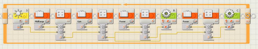
Figure 8-10. The Proportional line-following program does not use a Switch block; instead, it calculates the necessary power to drive the motors and keep the robot on the line
So far, the examples have dealt with robots that only use a single Light sensor to detect the edge of the line. But what if you added a second Light sensor and straddled the line? The FLL rules allow for two Light sensors even though the LEGO MINDSTORMS kits do not include a second sensor. You can purchase them separately if desired.
When you have two Light sensors, you want them to be spaced on your robot just a bit wider than the line it will try to follow. If the sensors are spaced too close together, you’ll never get a valid state for going straight; if they are too far apart, you will find your robot overcompensating direction changes when it hits the line. Ideally, neither sensor should see the line when the robot is centered over the line; they should only see the area next to the line.
If you want to use the Complex state method that we discussed earlier, you simply add a second Switch block, one for each Light sensor and motor. Each Light sensor is isolated to the motor on its side of the robot. Each Switch block has only three conditions, as seen in Table 8-3, Figure 8-11, and Figure 8-12’s robot with dual Light sensors.
Table 8-3. Complex State Conditions for Dual Light-Sensor Robots
| Light Sensor | Range Value | Action |
|---|---|---|
| Left | 0 | Sharp Turn to the Left: slow down motor B. |
| Left | 1 | Slight Turn to the Left: slow down motor B slightly. |
| Right/Left | 2 | Stay Straight: keep both motors equal. |
| Right | 1 | Slight Turn to the Right: slow down motor C slightly. |
| Right | 0 | Sharp Turn to the Right: slow down motor C. |
For this approach to work properly, both Light sensors need to straddle the line. If the robot gets into a position where both Light sensors see black, the robot simply slows down because the conditional switches slow both motors from trying to force the robot to turn. This can happen when a robot leaves the base and is expecting a line to follow just outside the base. Since the robot detects the border around the base, you can do one of two things: add a delay to the program to prevent line detection when the robot leaves the base, or allow the robot to slow down when it first detects the border, and then have it speed up again after it is past the border around the base.

Figure 8-11. Complex condition line-following program: a Switch block for each Light sensor and only three conditions

Figure 8-12. A robot with dual Light sensors installed
The lines on a game field can serve uses for navigation beyond line following. Many times, various areas on the game field are outlined by a line or box of some sort. The line may not be a true line, but rather a shape or an image. These shapes and images are still important and can be very helpful when trying to determine if your robot is in the right location. Be aware that these lines may not be simple black lines. Many times they are colored lines and requite a bit more effort to detect properly with an NXT Light sensor.
In the 2008 FLL Climate Connections game field shown in Figure 8-13, parts of the field are outlined with various colored lines. These were very useful for trying to navigate to a given area to perform a task. What made them tricky was that they were colored lines and that you had to cross over a large rainbow printed on the mat. The job wasn’t as simple as driving forward until you saw a red line. You had to time when the robot began looking or you had to count the number of red lines you encountered.

Figure 8-13. The 2008 FLL Climate Connections field mat
If you look at Figure 8-13, you see that it doesn’t have many lines that would be helpful for line following, but there are lots of thick lines that either outline or could guide a robot to a particular location on the field. These lines are there to help a robot navigate to particular locations. In the middle of the field is a lot of open space. It would be very easy for a robot to get lost in this space. The borders help a robot know when it has reached the desired location.
Let’s say your robot leaves base and is heading to the location labeled “Zone A”. After the robot leaves base, it is very dependent on odometry to find its way across the field. During this time, it should use its Light sensor to look for the thick black border around Zone A. You will have to be careful that the other colors on the field don’t confuse it—that rainbow has tripped up many robots. These are things that you need to consider when planning the task for your missions. What things may be in your way? What other markings on the mat can confuse your robot?
Now look at the 2007 FLL Power Puzzle field mat in Figure 8-14. It is very different from the Climate Connections mat in that it has well-defined zones with easy-to-track borders.
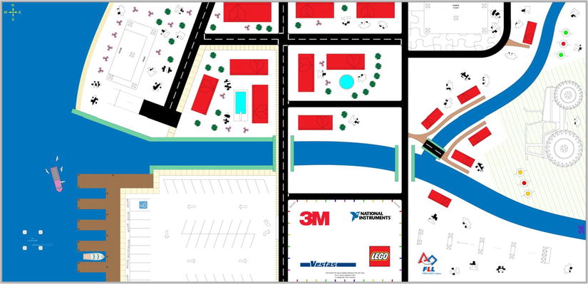
Figure 8-14. The 2007 FLL Power Puzzle field mat
There are a few roads that you can use for line following and the blue rivers are great for breaking up the different areas of the mat—giving your robot quick feedback on where it is located on the field. Down the middle there are three distinct black lines crossing the robot’s path as it leaves base heading north. These lines are great for counting and helping the robot learn where it is located. When you count lines, remember that you cannot merely count the number of times your Light sensor sees a black line. As a Light sensor travels over the line, it reads it multiple times because the sensor is very fast. You will have to include logic in your code to first look for a black line, and once found, increment the counter to look for the color white. Once white is found, look for black again. This process continues for however many lines you’re expecting to encounter. Figure 8-15 illustrates an example of such code in NXT-G.

Figure 8-15. NXT-G line-counter code
Many of the lines or areas that you encounter are not simple black-and-white lines; many of them are colored lines or edges. Even though we’re using the NXT Light sensor and not the NXT Color sensor, we can still detect different colors.
Ideally, you will still be able to calibrate your Light sensor on a white-and-black source. The color values will fall between the calibrated ranges of 0 and 100. It is best to first calibrate your Light sensor. Then run the light value view program, place your Light sensor over the various colors on the game field map, and record the values you read for each color. As long as you can calibrate your robot consistently, the color values should read the same.
Be careful! Some colors will share the same value. Many times red, green, and gray return the same Intensity values to the NXT Light sensor. This is why it is important to get a good reading on each color and keep track of which values register the most consistent results.
When you are thinking through your strategies for navigating the field, look for colors that contrast more drastically with other colors to help avoid confusion and make finding the navigation points easier. Thick lines are going to make better markers than thin or fuzzy lines and edges, of course. You really want anything that is unique and can produce consistent readings back to your program. Consistent markings produce consistent results.
In addition to the table walls, most game fields have some type of printing or markings on the field that your robot can use for alignment. The trick in making use of these markings is to use a second NXT Light sensor.
Aligning the robot using field markings can be very effective and give you a bit more flexibility than solely relying on the table walls. Ideally, your robot will take advantage of both types of squaring. With field markings, you can align the robot with various angles, depending on the markings on the field. On the 2008 FLL Climate Connections game field you can see that the different areas have thick-colored lines outlining them. If used correctly, these lines are great for helping line up a robot for various missions.
We will use these colored lines for lining up as we do with the walls, but instead of the ability to push up to a wall, we need to have smart code for our NXT to recognize that we are at a line and determine which direction the robot needs to turn to align itself with the line or marking. You will have two NXT Light sensors mounted parallel with each other on the robot. They need to be as wide apart as possible on the chassis.
The reason for having the sensors far part from each other is to prevent the robot’s turns from being drastic when lining up. Having the sensors far apart allows for a smooth and precise alignment. The closer together the sensors are located, the faster the second sensor will approach the line edge as the robot turns to square itself to the line. This will begin to make more sense once you learn more about the logic involved to turn the robot. Keep reading!
Your robot will have the two Light sensors on. It will be searching for the color line that you have programmed the robot to expect. For example, say the mission we’re going to tackle has a black line in front of it. A black line will regist15:3 er a low number reading on the Light sensor. So our NXT-G code, as seen in Figure 8-16, will tell each Light sensor to be on the lookout for a light reading with a low number, maybe 30 or lower depending on whether there is other printing on the field that we need to be concerned about. We don’t want to trigger a false positive on something that is not our line.
The robot is running along when the Light sensor on its right side detects a black line. Now we need to find that line with the left Light sensor. All the robot has to do is stop moving forward and turn to the right until the left Light sensor also detects the line. Once both Light sensors have found the edge of the line, the robot should align with the line.
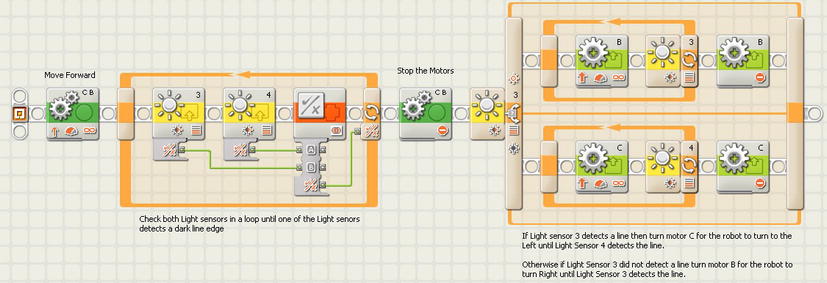
Figure 8-16. An NXT-G program using NXT Light sensors to align the robot with a line detected on the game field
Your robot is using the first Light sensor that detected the line as a pivot point. It will now turn along the pivot point until the other Light sensor reaches the line, as seen in Figures 8-17 and 8-18.
Having the Light sensors a good distance apart from each other ensures that you get a straight alignment with the line. If the sensors are too close together, it leaves more room for error in making proper alignment.

Figure 8-17. The first sensor detects when the robot encounters the line

Figure 8-18. The robot then pivots on the first sensor’s corner until the second sensor detects the line
Summary
Using and understanding lights and Light sensors can contribute to making your robot better navigate the field. They allow your robot to make smart decisions based on its environment.
Don’t be intimidated by the use of Light sensors. There can be a slight learning curve, but with some practice and lots of experimenting, you will find that the Light sensor is one of the best tools in your toolbox when it comes to building a winning LEGO robot.