Chapter Two. Drawing Lines and Shapes
The paradox of digital illustration is that often the simple things are complicated, and the complicated things are simple. Anyone can apply a complex set of effects (drop shadow, blur, even rotation) to a drawing. But on the other hand, drawing a curved line is probably the most essential and challenging skill you need to master Adobe Illustrator CS3. However, Illustrator has built-in tools for drawing shapes such as ellipses (including circles), rectangles (including squares), rounded rectangles, preset (but flexible) curves, and of course straight lines.
Drawing simple shapes in Illustrator can be counterintuitive because the process corresponds to Illustrator’s underlying vector logic. When you draw a line or shape, you don’t really draw a line. You define the anchor points, the magnitude of the curvature between them, and the properties of the stroke and fill that apply to the drawn object.
The upside is that your illustrations are infinitely scalable. Illustrator will generate a curve the size of the Grand Canyon as accurately as a curve the size of your thumbnail—without aliasing (causing jaggy curves).
Illustrator covers up this process, in a sense, by letting you “draw” on the artboard with drawing tools such as shape tools, line and curved line tools, and the Pencil tool. Illustrator then generates anchor points with defined curves on your drawing. Many people find the Pencil tool easier to use and more intuitive than the Pen tool.
The Pen tool, on the other hand, is the most powerful tool in Illustrator. It allows you to consciously define your own anchor points, and specifically, adjust the curve associated with them by manipulating two control points associated with each anchor. You’ll explore anchors and control points in this chapter. As you work with other ways of generating paths, keep in mind that you are actually creating anchors with curves defined by control points.
#12. Drawing Lines
Perhaps the simplest way to generate a path is to draw a straight line. Drawing a line with the Line tool is a good way to become familiar with generating paths in Illustrator. Drawing a curved line with the Arc tool is more challenging. When you draw an arc, you create a line segment that curves. Both the Line Segment tool and the Arc tool are found on the Line Segment gallery in the toolbox.
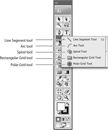
The Line Segment tool is the top tool in the toolbox gallery that includes the Arc tool, the Spiral tool, and Grid tools (Figure 12a).
Figure 12a. The Line tool and its toolbox gallery.
All tools in the Line Segment flyout can be used in two ways. You can generate a line digitally (defining it in a dialog), or you can draw it freehand on the artboard.
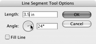
To generate a straight line digitally, click the Line Segment tool and then click once on the artboard. The Line Segment Tool Options dialog appears. Enter a line length (such as 1 in or 72 pt for points) in the Length field. Either enter an angle in the Angle field or interactively define the angle by dragging the clock hand (Figure 12b).
Figure 12b. Defining a line segment angle interactively in the Line Segment Tool Options dialog.
When you click OK in the Line Segment Tool Options dialog, you generate a line with a defined angle and length, starting from the point you clicked on the artboard.
Note
The Fill check box in the Line Segment Tool Options dialog is essentially inoperative; it only generates a fill if a number of line segments are joined using Pathfinder tools. See #21, “Combining Paths,” for an introduction to Pathfinder tools.
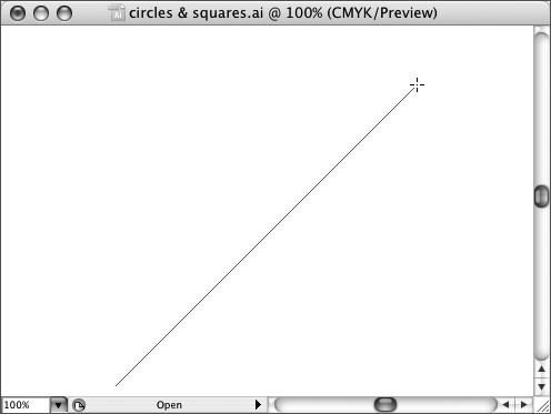
To draw a line freehand on the artboard, select the Line Segment tool in the toolbox (or press the key on the keyboard), and then click and drag your mouse on the artboard. When you release the mouse, the line segment is complete.
To constrain an angle to an increment of 45 degrees, hold down the Shift key as you draw the line segment. To draw a line segment symmetrically around a central radius, hold down the Option (Mac) or Alt (Windows) key.
Holding down Shift + Option (Mac) or Alt (Windows) as you draw a line segment generates a line that expands from a center point and is constrained to increments of 45 degrees (Figure 12c).
Figure 12c. Drawing a line radius at a 45-degree angle.
Just as you can define a straight line segment in a dialog, you can define and draw a curved line with the Arc tool. However, that requires you to think of an open convex curve with a slope of 38 based on the Y-axis, with a Y-axis length of 3.45 in and an X-axis length of 4 in! Therefore, we’ll avoid using the Arc tool dialog to generate a curve and just look at drawing arcs freehand.
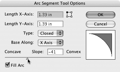
You’ll still need to use the Arc Segment Tool Options dialog to define the type of curve you want to draw. Before you draw a curve, double-click the Arc tool to open the dialog. Ignore the two Length boxes; you’ll define length as you draw the curve. Experiment with both Open- and Closed-type curves, and preview in the dialog to see the difference (closed curves are somewhat like pie segments). Experiment with both an X and Y base, and drag the Concave/Convex slider to define a curvature direction and radius. If you want to fill the inside of the arc, click the Fill Arc check box (Figure 12d).
Figure 12d. Defining a closed, filled Arc with an X-axis curve.
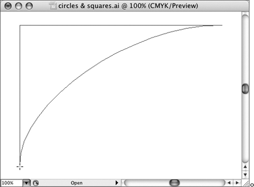
With your curve parameters defined in the dialog, click OK and then click and drag on the artboard with the Arc tool, as if you were drawing a straight line, to generate a curve (Figure 12e).
Figure 12e. Drawing a closed, filled arc with an X-axis curve.
#13. Drawing Ellipses and Circles
Like all shape tools, the Ellipse tool works in two different modes. You can digitally define the dimensions of your ellipse, or you can draw one freehand on the artboard.
Note
The stroke and fill colors of the ellipse are defined by the colors you defined in the Fill and Stroke color swatches in the toolbox or the Control panel.
The Rectangle, Rounded Rectangle, Ellipse, Polygon, Star, and Flare tools are found on the same gallery in the toolbox (Figure 13a).
Figure 13a. The Shapes tool palette menu in the toolbox.
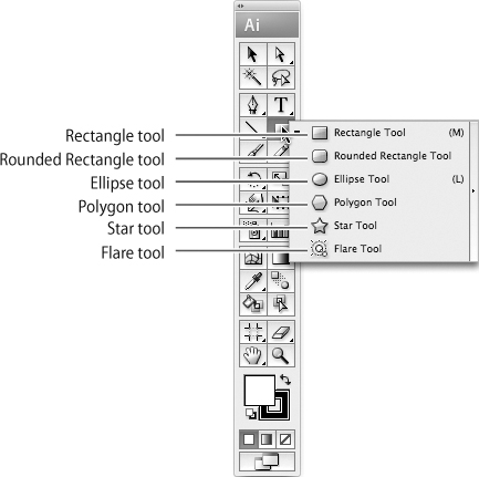
By default, the Rectangle tool is visible, and other tools are accessed from the flyout or by tearing off the Shapes flyout.
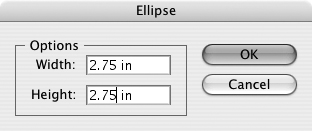
To digitally generate an ellipse (including a circle), click the Ellipse tool, and then click once on the artboard. The Ellipse dialog opens. Enter values for the width and height of the ellipse (Figure 13b).
Figure 13b. Defining the dimensions of a circle.
Note
Naturally, to draw a circle you enter the same values for width and height.
When you click OK in the Ellipse dialog, an ellipse is created at the location on which you originally clicked.
To draw an ellipse freehand, select the Ellipse tool in the toolbox, and then click and drag your mouse on the artboard. When you release the mouse button, the ellipse will be completed.
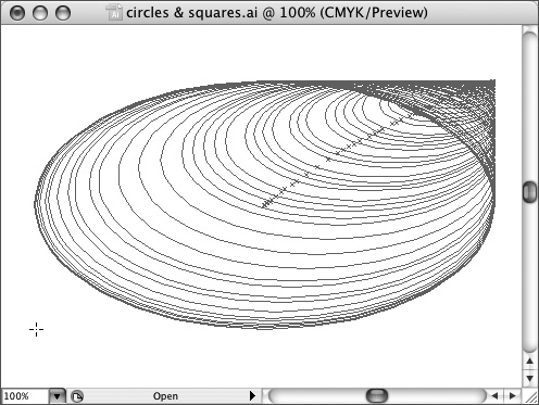
To draw multiple ellipses, press the Tilde key (~) on your keyboard as you draw. The effect is an interactively generated set of ellipses (Figure 13c).
Figure 13c. Drawing multiple ellipses using the Tilde key.
#14. Drawing Spirals
The Spiral tool generates multiple shrinking arcs and has additional options that allow you to define the radius of a spiral, the decay (intensity of spiraling), and the number of curved segments.
You can either define a spiral in the Spiral dialog or set the parameters in the dialog and then draw freehand. Since spirals are complex sets of paths, it’s often easier to define them in the dialog than it is to wrestle with them on the artboard.
To define a spiral, click the Spiral tool on the Line Segment gallery, and then click on the artboard. The Spiral dialog opens (Figure 14).
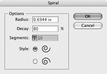
The Spiral dialog defines the radius (of the first segment of the spiral), the decay (degree of spiraling), the number of segments, and the style (clockwise or counterclockwise rotation).
The number of segments defines how many times the spiral winds around, with each wind containing four segments. As you increase the segment number, more winds are created in the center of the spiral.
Spiral settings are sticky; that is, once you define them you can draw freehand spirals (of different radii) that maintain the attributes you defined when you last opened the Spiral dialog. However, you can alter the style (rotation direction) of the Spiral by how you draw.
#15. Drawing Rectangles
The Rectangle tool and the Rounded Rectangle tool on the Rectangle tool flyout in the toolbox quickly generate either a regular or rounded rectangle.
Drawing a rectangle is easy to do in Illustrator. Just select the Rectangle tool in the toolbox, or press M to select the tool. Then click and drag your mouse to anywhere on the artboard.
Keyboard constraints for rectangles are similar to those for ellipses and are very handy:
• Press the Shift key as you click and drag your mouse to constrain the rectangle to a square.
• Press Option (Mac) or Alt (Windows) as you click and drag your mouse to define the rectangle using the click point as its center point.
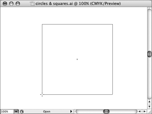
• Press Shift + Option (Mac) or Alt (Windows) to draw a square with the initial point as the center of the square (Figure 15a).
Figure 15a. Drawing a square, defined and drawn from a center point instead of a corner.
There are no options to set in the Rectangle dialog besides defining the height and width of the rectangle. However, you can define a rectangle precisely and digitally by clicking the Rectangle tool and then clicking on the artboard (without dragging). The Rectangle dialog appears (Figure 15b).
Figure 15b. Defining a rectangle in the Rectangle dialog.
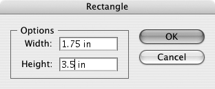
Enter a width and height in the dialog, and click OK to generate a precisely sized rectangle.
Draw a rounded rectangle by selecting the Rounded Rectangle tool from the Rectangle tool flyout. You can click and drag to interactively define the rounded rectangle, or you can click once to define the rounded rectangle in a dialog.
Note
Use the Up and Down keys on your keyboard to interactively define the rounded rectangle after you click and drag to define the dimensions of the rounded rectangle, but before you release your mouse button.
However, you should be aware of the option in the Rounded Rectangle dialog that allows you to define the size of the corner radius (Figure 15c).
Figure 15c. Defining a corner radius of .25 inches.
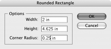
After you define the corner radius, clicking OK in the dialog generates a rectangle with the dimensions and radius you defined at the point on the artboard that you clicked with the Rounded Rectangle tool. Subsequent rounded rectangles will maintain the same radius until you redefine the radius in the Rounded Rectangle tool dialog.
#16. Drawing Polygons and Stars
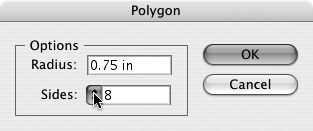
Illustrator’s polygons and stars can have from 3 to 1000 points or sides. So before you start drawing, you’ll want to use the Polygon or Star dialog to define the number of points and sides, among other options.
To define sides or points for a polygon or star, select the tool (both the Polygon and Star tools are accessed from the Rectangle tool gallery) and click on the artboard. Use the dialog that appears to define the number of sides or points you want, and then click OK. When you click OK in the dialog, you generate a star or polygon (Figure 16a).
Figure 16a. Defining an octagon.
Once you define the number of points in a star, or sides in a polygon, that setting remains in effect until you redefine it. So, for example, after you define a star as having six points, you can continue to draw six-pointed stars interactively with your mouse cursor.
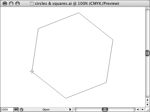
When you draw a star or polygon on the artboard, it’s as if you are drawing a rectangle that frames the shape you want to create. As you draw a star or shape, you can rotate the object as you draw. First, draw the shape at the size you want it to appear. Then, without releasing your mouse button, draw a clockwise or counterclockwise curve to tilt the shape (Figure 16b).
Figure 16b. Rotating an octagon as you draw.
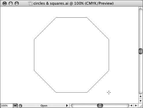
Pressing and holding the Shift key as you draw a star or polygon locks the alignment of the shape so that the base is parallel with the edge of the artboard. While holding down the Shift key, you cannot rotate stars or polygons as you draw (Figure 16c).
Figure 16c. Constraining an octagon so that the bottom side is parallel to the bottom of the artboard.
As with other shapes, the Tilde key allows you to generate multiple stars (or shapes) interactively as you draw (Figure 16d).
#17. Drawing Grids
Need a quick rectangular grid for displaying a lot of data in your illustration or a circular grid for a design layout? Rectangular and Polar Grids are created by first double-clicking the tool to define options, and then drawing on the artboard. The Rectangular Grid tool and the Polar Grid tool are found on the Line Segment tool gallery in the toolbox.
Unlike shape tools (such as the Rectangle tool), you can double-click either the Rectangular Grid tool or the Polar Grid tool to open the tool dialog.
If you draw grids, the width and height dimensions in the dialog are irrelevant. You can define the number of grids in a rectangular grid by entering values into the Horizontal Dividers and Vertical Dividers fields in the Rectangular Grid Tool Options dialog.
The Skew field in the dialog allows you to generate irregularly divided grids. Skewing, however, is affected by which corner reference point you select in the dialog and how you draw the grid. You can experiment with different skew settings and drawing distorted grids.
In the Polar Grid Tool Options dialog (accessed by double-clicking the Polar Grid tool), the Concentric Dividers value defines the number of concentric circles (rings), and the Radial Dividers value defines the number of pie slices.
Like the Rectangular Grid Tool Options dialog, the Polar Grid Tool Options dialog has Skew sliders. These sliders warp the polar grid to skew dividers toward the inside or outside of the circumference of the grid, or they irregularly space the pie slice dividers.
#18. Drawing with the Pencil Tool
The Pencil tool is an intuitive way to draw freehand in Illustrator. It’s especially effective if you have a drawing tablet connected to your computer, in which case you would have the closest thing to simply drawing and having your lines converted to vectors.
The Pencil tool has a companion, the Smooth tool, which is located in the Pencil tool flyout. The Smooth tool irons out wrinkles in the often awkward paths generated by the Pencil tool.
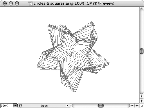
While the Pencil tool is more intuitive than the Pen tool, it’s also difficult to wield. The key to drawing smooth curves is to set the Smoothness value so that the Pencil tool helps smooth out your curves just the right amount as you draw. You set Fidelity and Smoothness in the Pencil Tool Preferences dialog that opens when you double-click the Pencil tool. Experiment with different Fidelity and Smoothness tolerances to find settings that provide the help you need in smoothing out curves without restricting your ability to draw. More Fidelity tolerance and Smoothness tolerance makes it easy to produce a very smooth curve with the Pencil tool (Figure 18a).
Figure 18a. Drawing with the Pencil tool with maximum Smoothness and Fidelity tolerance.
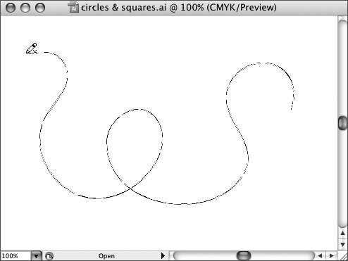
Low Fidelity tolerance and Smoothness tolerance settings facilitate more accurate curves (Figure 18b).
Figure 18b. Drawing with the Pencil tool with minimum Smoothness and Fidelity tolerance.
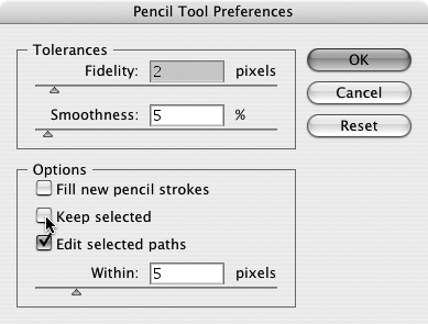
The Pencil Tool Preferences dialog also has three check boxes. The Fill new pencil strokes check box applies the focused fill color to the paths you draw. The Keep selected check box makes the Pencil tool work like other tools; that is, when you draw a curve, it is selected (and you can edit or delete it). Deselecting this check box makes the Pencil tool work more like a real pencil—you draw one curve, and then you draw another (Figure 18c).
Figure 18c. Deselecting the Keep selected check box in the Pencil Tool Preferences dialog.
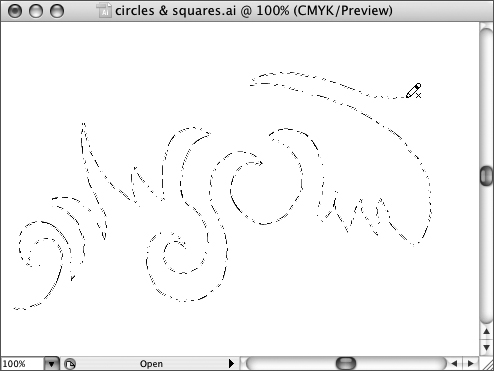
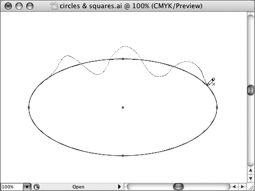
The Pencil tool can also function as an editing tool. If you select the Edit selected paths check box, you can draw over an existing path with the Pencil tool to reshape it (Figure 18d).
Figure 18d. Reshaping an existing path with the Pencil tool in edit mode.
#19. Drawing with the Pen Tool
As noted in the introduction to this chapter, the Pen tool is both the heart of Illustrator and the tool that causes the most fear and frustration. This power can be unleashed and the frustration can be overcome if you master the tool step by step.
The best way to start using the Pen tool is to generate line segments. Note that you generate, not draw. To create a line, you define two anchor points instead of clicking and dragging. You generate a straight line with the Pen tool by clicking once, and then clicking again at another location on the artboard. Additional clicks add more line segments.
As you generate anchors, the Pen tool remains active until you close the path. If the path is not closed, you add points anywhere in your document simply by clicking. There are two ways to close a line segment path: Select another tool, or press Command (Mac) or Control (Windows) while you click anywhere on your document to close that path. You can also end a series of line segments by closing the path. To do this, move the Pen cursor over the original anchor point and click. As you move the cursor over the starting anchor point, the cursor displays as a circle (Figure 19a).
Figure 19a. Closing a path with the Pen tool.
Once you’re comfortable with the process of defining anchors with the Pen tool, the next step is learning to control the smoothness of the anchors. By default, the Pen tool generates sharp-angled, not smooth, anchors. As noted earlier, it is possible to define anchor location and anchor curves all at once. However, this takes some expertise. Start out by drawing sharp corner anchors, and then convert them to smooth anchors. You can do this by following these steps:
- Draw a group of line segments with the Pen tool.
Note
I’m returning to the shorthand term draw, now that I’ve emphasized that you are really defining anchors.
- Select the Convert Anchor Point tool from the Pen tool flyout in the toolbox.
- Click an anchor with the Convert Anchor Point tool and drag the anchor in any direction. The anchor itself does not move. Instead, control points appear. Drag the selected control point away from the anchor and experiment with rotating the control point to control the curve (Figure 19b).
Figure 19b. Rotating a control point to change a curve.
Moving control points changes the direction of the anchor curve. Stretching out the control point handles (the lines that connect the control point to the anchor) increases the intensity of curvature.
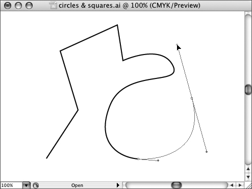
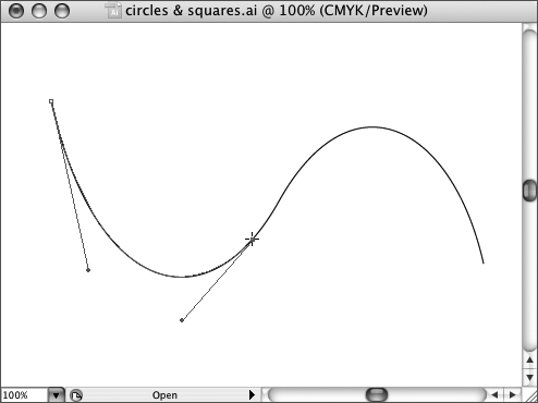
After you are comfortable manipulating anchor control points with the Convert Anchor Point tool, you can combine the process of defining an anchor and manipulating control points. Click to define an anchor with the Pen tool, and then drag to define the control points (Figure 19c).
Figure 19c. Defining a curve while creating an anchor with the Pen tool.
Note
Smart Guides provide help in constraining smooth curves; they kick in when control points are moved to angles with increments of 45 degrees.
Selecting, moving, and deleting individual anchors is done with the Direct Selection tool. The easiest way to select a handle and activate the control lines is to click an anchor point with the Direct Selection tool. As you hover over an anchor point, the Direct Selection tool cursor displays as an open square.
The Convert Anchor Point tool converts sharp-angled anchors to smooth anchors. It also works the other way. If you want to convert a smooth anchor back to a regularly angled point, click the Convert Anchor Point tool again. To create hybrid anchors, in which one control point is smooth and the other is angled, select a control point with the Direct Selection tool and drag it back into the anchor (Figure 19d).
Figure 19d. Creating a hybrid anchor with the Direct Selection tool.
Illustrator has features that allow you to automatically clean up paths. Choose Object > Path > Simplify to open the Simplify dialog and clean up selected curves. The Simplify dialog has a Curve Precision and Angle Threshold slider, as well as check boxes for Straight Lines, Show Original, and Preview. A higher Curve Precision value increases the number of anchors that will be left after simplifying. The Angle Threshold slider can be used to prevent some angle anchors from being smoothed into curves. The Straight Lines check box changes paths to straight lines. Don’t be too concerned about the meaning of all the settings in the dialog. Instead, click both the Show Original and Preview check boxes. This will display the original anchors in red and the anchors that result from simplifying in blue. Play with the settings until your preview curve looks the way you want it.
#20. Using the Eraser and Path Eraser Tools
Illustrator’s Eraser tool works like a chalkboard eraser. The Path Eraser tool, new to Illustrator CS3, allows you to erase along a path, and it only erases along a path. An odd, but perhaps useful way to envision the difference between the tools is to think of the Path Eraser tool as a can opener and the Eraser tool as an ice cream scoop.
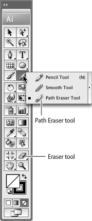
The Path Eraser tool is located on the Pencil tool gallery. The Eraser tool is visible in the toolbox as part of the Eraser tool gallery (Figure 20a).
Figure 20a. The Path Eraser tool and the Eraser tool.
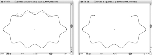
To use the Path Eraser tool, select the path to which you will apply the erasing. Then draw along the path with the Path Eraser tool (Figure 20b).
Figure 20b. Erasing a segment of a path with the Path Eraser tool.
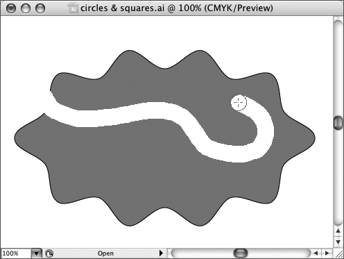
To use the Eraser tool, select the path to which you will be applying the erasing and “draw” anywhere in that path (including in the fill) with the Eraser tool (Figure 20c).
Figure 20c. Erasing with the Eraser tool.
#21. Creating Compound Paths
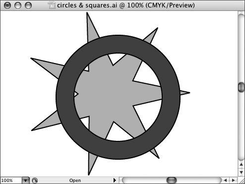
A compound path is specially shaped to allow a “hole” in it. The humble donut is a good example of a compound path. Compound shapes can be placed over other shapes and allow the underlying shape to peek through (Figure 21a).
Figure 21a. The dark disk is a compound shape, and the underlying object shows through the middle.
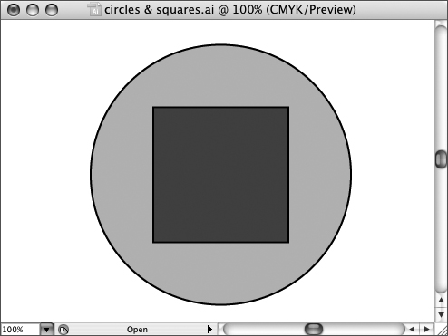
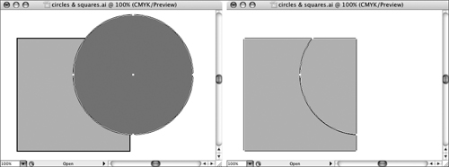
To create a compound path, create two shapes that overlap. With both shapes selected, choose Object > Compound Path > Make (Figure 21b).
Figure 21b. The outer circle and the inner square will become a single compound shape.
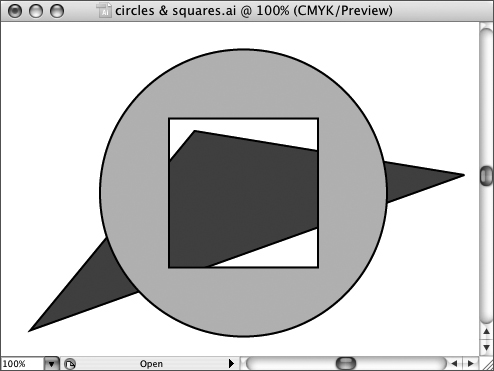
You can test the compound shape by moving it over another object and noting the “hole” inside (Figure 21c).
Figure 21c. Placing a compound shape on top of another shape.
#22. Dividing Paths with the Scissors and Knife Tools
There are many ways to cut a path in Illustrator. You can “erase” along a path with the Path Eraser tool (found in the Pencil tool flyout) to delete a segment of a stroke. If you simply want to divide a line segment, click on the path with the Scissors tool. This divides the path into two paths, each of which can be edited, deleted, or moved separately (Figure 22a).
Figure 22a. Cutting a path with the Scissors tool.
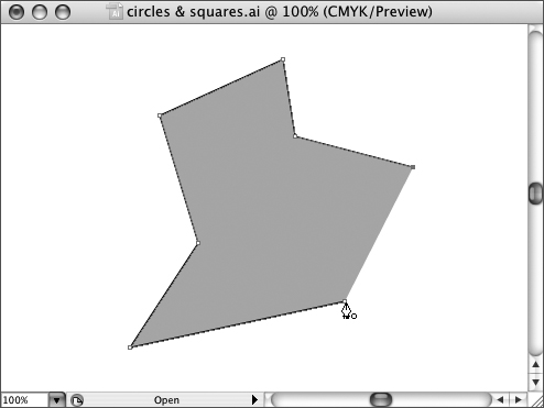
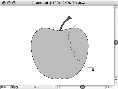
The Scissors tool works neatly on line segments (straight or curved). On closed paths, clicking once creates an incision (adding two anchors at the point on the path). Clicking a second time results in two separate open paths. The Knife tool is “drawn” (click and drag) onto a path, creating new path segments. If you drag completely across an object, you create two separate closed paths. You can carve out a section of an object with the Knife tool by clicking and dragging, as if you were carving with a knife (Figure 22b).
Figure 22b. Slicing an apple with the Knife tool.
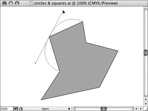
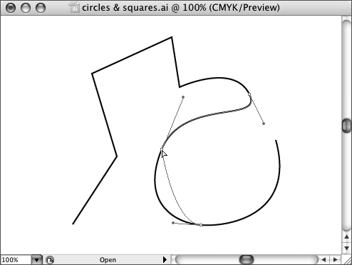
To use one shape to cut another, place the cutting shape on top of the shape to be cut, and choose Object > Path > Divide objects below. For example, if you want to use a circle to cut a corner off a square, place the circle on the square and use the Path Divide menu option (Figure 22c).
Figure 22c. Using a circle to cut a radius corner off a square.
#23. Clipping with Masks
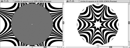
Clipping masks are used to, in effect, draw a frame around a section of an illustration and trim out everything else. The components of a clipping mask are the object to be masked and the masking object. You first create the object to be masked. Then you move the masking object on top of the object to be masked (Figure 23a).
Figure 23a. Using a circle as a mask on an illustration.
Note
Clipping masks can be any vector object, including type. You cannot use raster images (imported bitmap images) as clipping masks.
Masking objects define what section of an object will be visible. In that way, they are the opposite of a face mask, which defines what section of your face will be hidden. When you create a masking object, it doesn’t matter what color or stroke you apply. The masking object disappears when it operates as a mask; the outline of the shape simply defines what is revealed in the underlying object. To generate a mask from an object, and a masking shape, select both the shape and the masking object and choose Object > Clipping Mask > Make.
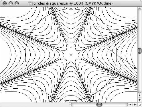
Masks can be edited. After you have applied a mask, you can edit the shape and location. The hard part is to see your mask outline to select it, since the mask is invisible. If necessary, switch to Outline mode to locate the mask (Figure 23b).
Figure 23b. Editing a mask object.
#24. Defining an Interactive Crop Area
The Crop Area tool, new to Illustrator CS3, provides a host of convenient ways to define what part of an illustration will print (or be exported to another file format, like Web-compatible raster image formats).
By default, the crop area in an Illustrator document is the artboard. You set the size of the artboard when you create a new document and choose a size in the New Document dialog. But you can easily change that using the Crop Area tool.
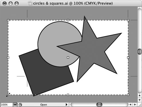
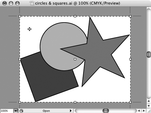
To define a crop area with the Interactive Crop tool, first select the tool. You can automatically define the crop area to include all objects in the document by simply clicking once on the artboard (Figure 24a).
Figure 24a. Automatically defining a crop area to include all objects in the illustration.
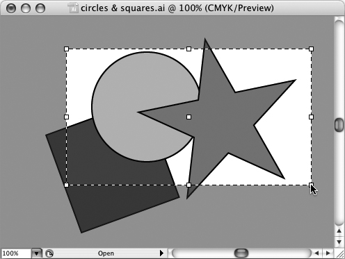
Or, you can use the Crop Area tool to click and drag to define the crop area, just as you would if you were drawing a rectangle (Figure 24b).
Figure 24b. Defining a crop area by drawing with the Crop Area tool.
Once you define a crop area with the Crop Area tool, you can adjust the location of the crop area by clicking the Crop Area tool again to select the existing crop area and dragging that crop area. Or, you can click and drag on any of the corner or side handles to resize the crop area (Figure 24c).
Figure 24c. Resizing the crop area.