
4. Editing and Combining Shapes and Paths
Lesson overview
In this lesson, you’ll learn how to do the following:
Cut with the Scissors tool.
Join paths.
Work with the Knife tool.
Outline strokes.
Work with the Eraser tool.
Create a compound path.
Work with the Shape Builder tool.
Work with Pathfinder effects to create shapes.
Work with the Reshape tool.
Edit strokes with the Width tool.

This lesson will take about 45 minutes to complete. To get the lesson files used in this chapter, download them from the web page for this book at adobepress.com/IllustratorCIB2022. For more information, see “Accessing the lesson files and Web Edition” in the Getting Started section at the beginning of this book.
Soon after you begin creating simple paths and shapes, you will most likely want to use them to create more complex artwork. In this lesson, you’ll explore how to edit and combine shapes and paths.
Starting the lesson
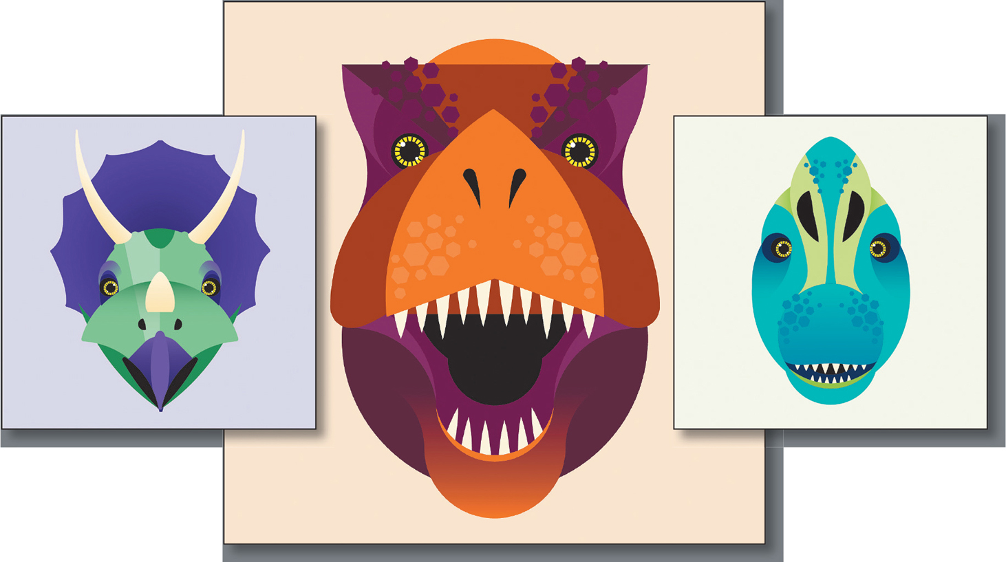
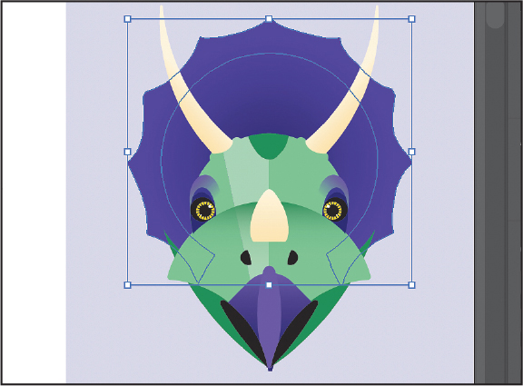
In Lesson 3, you learned about creating and making edits to basic shapes. In this lesson, you’ll take basic shapes and paths and learn how to edit and combine them to create artwork for a few dinosaur illustrations.
![]() Note
Note
If you have not already downloaded the project files for this lesson to your computer from your Account page, make sure to do so now. See the “Getting Started” section at the beginning of the book.
To ensure that the tools function and the defaults are set exactly as described in this lesson, delete or deactivate (by renaming) the Adobe Illustrator preferences file. See “Restoring default preferences” in the “Getting Started” section at the beginning of the book.
Start Adobe Illustrator.

Choose File > Open. Locate the file named L4_end.ai, which is in the Lessons > Lesson04 folder that you copied onto your hard disk, and click Open. This file contains the finished artwork.
Choose View > Fit All In Window; leave the file open for reference, or choose File > Close (I closed it).

Choose File > Open. In the Open dialog box, navigate to the Lessons > Lesson04 folder, and select the L4_start.ai file on your hard disk. Click Open.
Choose File > Save As. If the Cloud Document dialog box opens, click Save On Your Computer to save it locally.
 Tip
TipBy default, the .ai extension shows on macOS, but you can add the extension on either platform in the Save As dialog box.
In the Save As dialog box, change the name to Dinosaurs.ai (macOS) or Dinosaurs (Windows), and choose the Lesson04 folder. Leave Adobe Illustrator (ai) chosen from the Format menu (macOS) or Adobe Illustrator (*.AI) chosen from the Save As Type menu (Windows), and then click Save.
In the Illustrator Options dialog box, leave the Illustrator options at their default settings, and click OK.
Choose Window > Workspace > Reset Essentials.
![]() Note
Note
If you don’t see Reset Essentials in the Workspace menu, choose Window > Workspace > Essentials before choosing Window > Workspace > Reset Essentials.
Editing paths and shapes
In Illustrator, you can edit and combine paths and shapes in various ways to create your artwork. Sometimes that may mean starting with simpler paths and shapes and using different methods to produce more complex paths. The methods and tools you will use include working with the Scissors tool (![]() ), the Knife tool (
), the Knife tool (![]() ), and the Eraser tool (
), and the Eraser tool (![]() ), outlining strokes, joining paths, and more.
), outlining strokes, joining paths, and more.
Cutting with the Scissors tool
Several tools allow you to cut and divide shapes. You’ll start with the Scissors tool (![]() ), which splits a path at an anchor point or on a line segment to create an open path. Next, you’ll cut a shape with the Scissors tool and reshape it.
), which splits a path at an anchor point or on a line segment to create an open path. Next, you’ll cut a shape with the Scissors tool and reshape it.
Click the View menu, and make sure that the Smart Guides option is selected. A checkmark appears when it’s selected.
Choose 1 Dino 1 from the Artboard Navigation menu in the lower-left corner of the Document window. Choose View > Fit Artboard In Window to make sure the artboard fits in the document window.

Select the Selection tool (
 ) in the toolbar, and click the purple shape with the yellow stroke on the left side of the artboard.
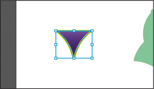
Press Command and + (macOS) or Ctrl and + (Windows) three times to zoom in to the selected artwork.
After you modify this shape, you’ll add it to the dinosaur head on the right side of the same artboard to complete the beak.
With the shape selected, in the toolbar press and hold on the Eraser tool (
 ), and select the Scissors tool (
 ).
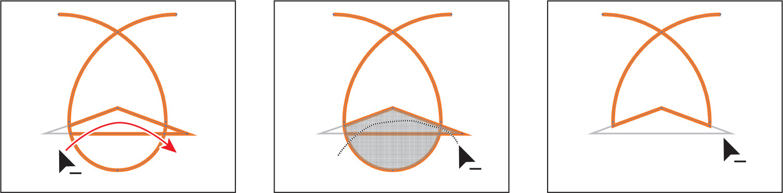
).Move the pointer over the top edge of the shape, in the middle (see the first part of the following figure). When you see the word “intersect” and a vertical magenta line, click to cut the path at that point, and then move the pointer away.

Cuts made with the Scissors tool must be somewhere on a line or a curve rather than on an end point of an open path. When you use the Scissors tool to click the stroke of a closed shape, like the shape in this example, the path is cut where you click so that it becomes an open path.
 Note
NoteTo learn more about open paths and closed paths, see the section “Working with basic shapes” in Chapter 3.
Select the Direct Selection tool (
 ) in the toolbar. Move the pointer over the selected (blue) anchor point, and drag it up.
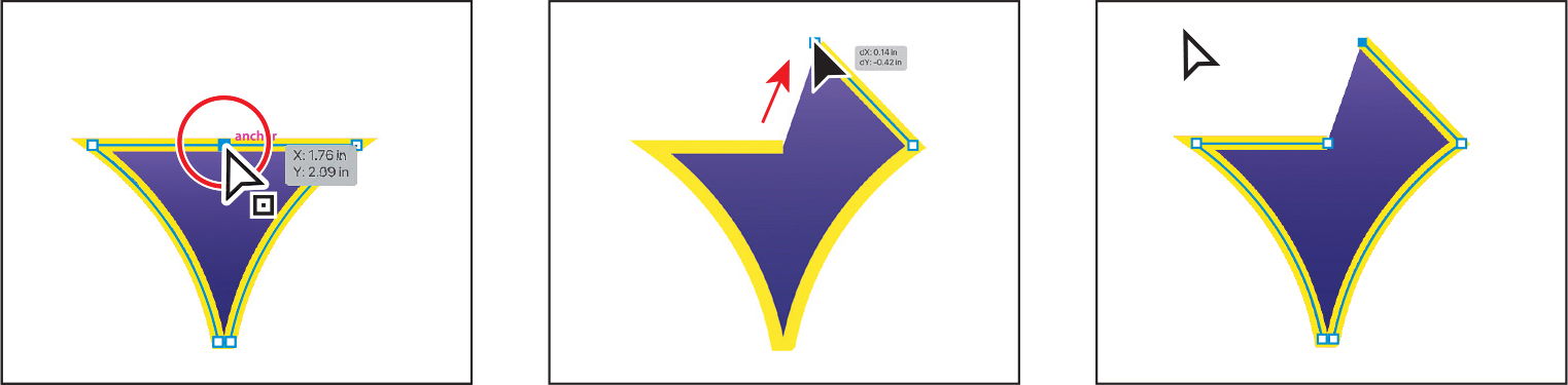
From where you originally cut the shape, drag the other anchor point up and to the left until a magenta alignment guide shows, indicating it’s aligned with the other anchor point you just dragged.

Notice that the stroke (the yellow border) doesn’t go all the way around the shape. That’s because cutting a shape with the Scissors tool makes an open path. If you only want to fill the shape with a color, it doesn’t have to be a closed path. It is, however, necessary for a path to be closed if you want a stroke to appear around the entire fill area.
Joining paths
Suppose you draw a “U” shape and later decide to close the shape, essentially joining the ends of the “U” with a straight path. If you select the path, you can use the Join command to create a line segment between the end points, closing the path.

When more than one open path is selected, you can join them to create a closed path. You can also join selected end points of two separate paths. Next, you’ll join the ends of the path you just edited to create a closed shape again.
![]() Tip
Tip
If you wanted to join specific anchor points from separate paths, select the anchor points, and choose Object > Path > Join or press Command+J (macOS) or Ctrl+J (Windows).
Select the Selection tool (
) in the toolbar. Click away from the path to deselect it, and then click in the purple fill to reselect it.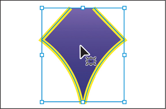
This step is important because only one anchor point was left selected from the previous section. If you were to choose the Join command with only one anchor point selected, an error message would appear. By selecting the whole path, when you apply the Join command, Illustrator simply finds the two ends of the path and connects them with a straight line.
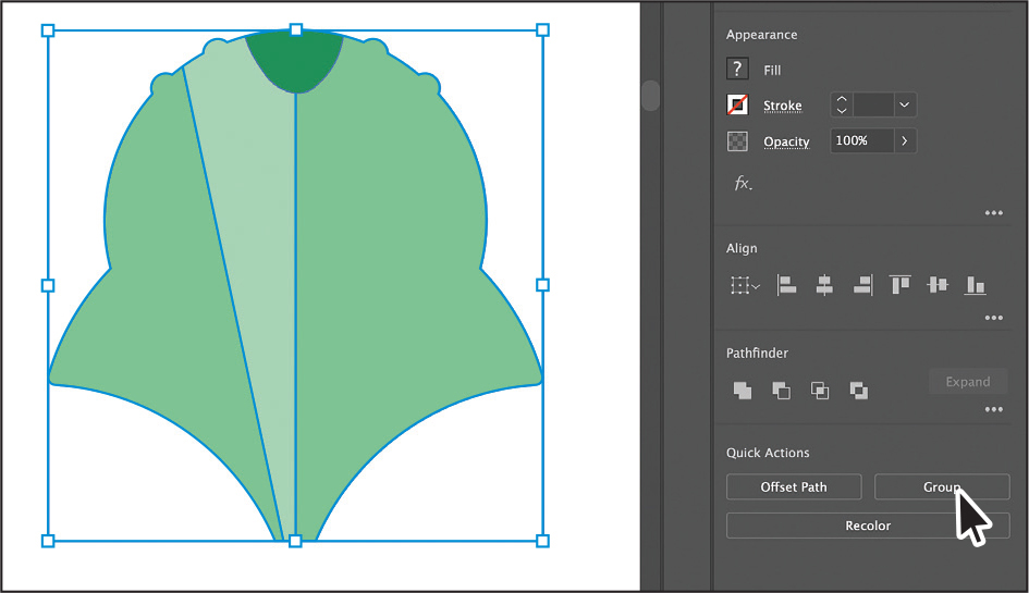
Click the Join button in the Quick Actions section of the Properties panel.

When you apply the Join command to two or more open paths, by default Illustrator first looks for and joins the paths that have end points located closest to each other. This process is repeated every time you apply the Join command until all paths are joined.
TipIn Lesson 6, you’ll learn about the Join tool (
 ), which allows you to join two paths at a corner, keeping the original curve intact.
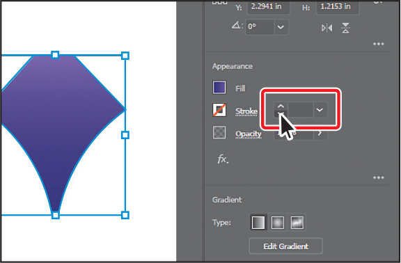
In the Properties panel, change the stroke to 0 by clicking the down arrow icon until the stroke is removed.
Next, you’ll round the corners on the top of the shape.
Select the Direct Selection tool (
) in the toolbar, and drag across the top of the shape to select the top two anchors.Drag one of the corner radius widgets toward the center of the shape to round the corners.

Choose Select > Deselect, and then choose File > Save.
Cutting with the Knife tool
You can also use the Knife tool (![]() ) to cut vector artwork. Using the Knife tool, you drag across a shape, and instead of creating open paths, you end up with closed paths.
) to cut vector artwork. Using the Knife tool, you drag across a shape, and instead of creating open paths, you end up with closed paths.
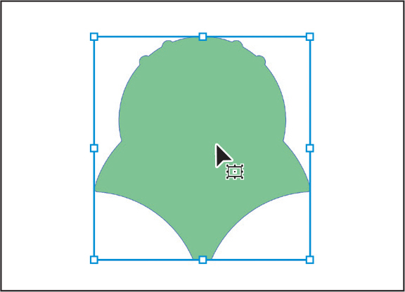
Press the spacebar to access the Hand tool, and drag in the document window to see the green shape to the right.
With the Selection tool (
) selected, click the green shape.Any objects selected will be cut by the Knife tool. If nothing is selected, it will cut any vector objects it touches.

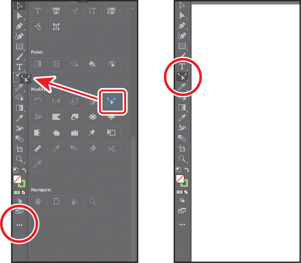
Click Edit Toolbar (
 ) at the bottom of the toolbar. Scroll in the menu that appears and toward the bottom of the menu you should see the Knife tool (
 ). Drag the Knife tool directly onto the Scissors tool (
 ) in the toolbar. When the Scissors tool shows a highlight, release to add the Knife tool to the list of tools.
Press the Escape key to hide the menu.
With the Knife tool now selected in the toolbar, move the Knife pointer (
 ) above the selected shape. Drag in a “U” shape to cut into the shape.
Choose Select > Deselect.
Select the Selection tool (
), and click the new shape on the top (see the following figure).Click the Fill color box in the Properties panel, make sure the Swatches option (
 ) is selected in the panel that appears, and click to select a darker green. I chose the color named “Dark green.”
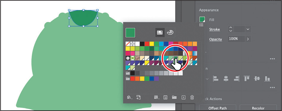
Choose Select > Deselect.
Cutting in a straight line with the Knife tool
By default, as you just saw, dragging across a shape with the Knife tool makes a free-form cut that is not straight. Next, you’ll see how to cut artwork in a straight line with the Knife tool to give the dinosaur head (the green shape) a highlight.
With the Selection tool (
) selected, click the large light green shape.Select the Knife tool (
 ). Move the pointer just above the top of the shape. Press the Caps Lock key to turn the Knife tool pointer into crosshairs (
 ).
).The crosshairs pointer is more precise and can make it easier to see exactly where you begin cutting.
Press and hold Option+Shift (macOS) or Alt+Shift (Windows), and drag down all the way across the shape to cut it into two. Release the mouse button and then the keys.
NotePressing the Option/Alt key keeps the cut straight. Adding the Shift key (Option/Alt-Shift) constrains the cutting to a multiple of 45°.
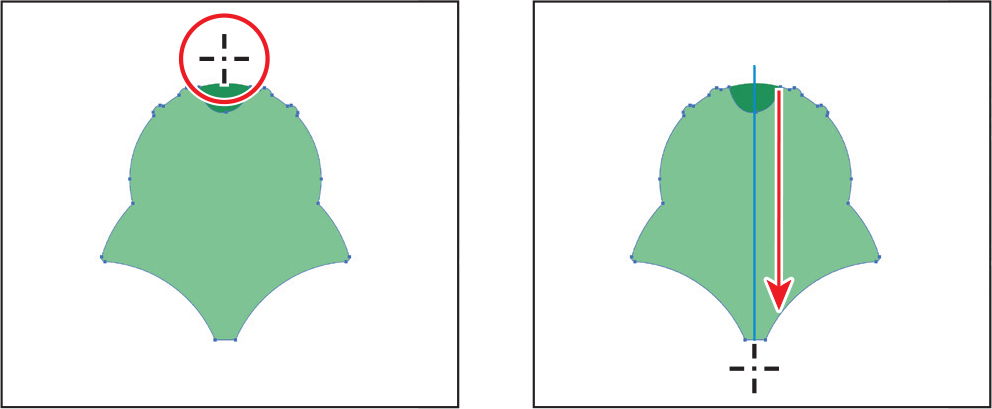
Press and hold Option (macOS) or Alt (Windows), and drag down from the top of the shape, at a slight angle, all the way across the shape to cut it into two. Release the mouse button and then the key. This way, you can cut in a straight line in any direction.

Choose Select > Deselect.
Select the Selection tool (
), and click the middle shape you just created (see the first part of the following figure).Click the Fill color box in the Properties panel, make sure the Swatches option (
) is selected in the panel that appears, and click to select a lighter green.
Drag across all of the green shapes to select them.
Click the Group button in the Quick Actions section of the Properties panel.
Press the Caps Lock key to turn off the pointer crosshairs.
Outlining strokes
A path, like a line, can show a stroke color but not a fill color by default. If you create a line in Illustrator and want to apply both a stroke and a fill, you can outline the stroke of a path, which converts it into a closed shape (or compound path). Next, you’ll outline the stroke of a line so you can erase parts of it in the next section to make the final part used to complete the first dinosaur.
Press the spacebar to access the Hand tool, and drag in the document window to see the purple circle to the right.

With the Selection tool (
) selected, click the path of the purple circle.To erase part of the circle and make it look like a dinosaur frill, the circle will need to be a filled shape, not a path. For an example of what a frill looks like, see the figure at the start of the next section, “Using the Eraser tool.” You should also see a set of gray lines that look like the spokes of a wheel. Those are just guides used for erasing. They were created by duplicating a straight line several times, and individually rotating each line 30° from the last.

Choose Object > Path > Outline Stroke.
This creates a filled shape that is a closed path. Next, you’ll erase parts of the shape.
Using the Eraser tool
The Eraser tool (![]() ) lets you erase areas of your vector artwork. You can use the Eraser tool on paths, compound paths, paths inside Live Paint groups, and clipping content. Without any objects selected, you can erase any object that the tool touches across all layers. If any artwork is selected, only that artwork can be erased.
) lets you erase areas of your vector artwork. You can use the Eraser tool on paths, compound paths, paths inside Live Paint groups, and clipping content. Without any objects selected, you can erase any object that the tool touches across all layers. If any artwork is selected, only that artwork can be erased.
Next, you’ll use the Eraser tool to erase part of the selected shape so it looks like a triceratops frill (see the figure at right).

![]() Note
Note
You cannot erase raster images, text, symbols, graphs, or gradient mesh objects.
Press and hold down the mouse button on the Knife tool (
 ), and select the Eraser tool (
 ) in the toolbar.
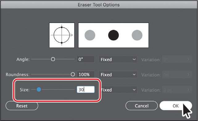 Tip
TipWith the Eraser tool selected and nothing selected in the document, you could also click the Tool Options button at the top of the Properties panel to see the options dialog box.
Double-click the Eraser tool (
) in the toolbar to edit the tool properties. In the Eraser Tool Options dialog box, change Size to 30 pt to make the eraser larger. Click OK.You can change the Eraser tool options, depending on your needs.
Move the pointer above the selected purple circle. Between two guide lines, drag in a “U” shape to create a scallop.
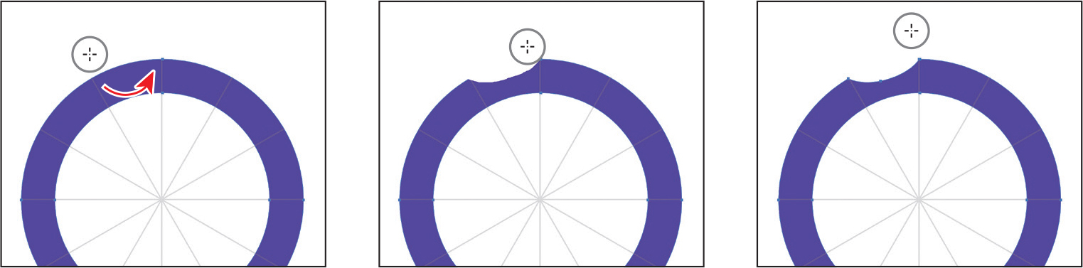
When you release the mouse button, part of the shape is erased, and the shape is still a closed path. To finish, you’ll erase the bottom of the circle shape.
Repeat this around the circle as you see in the figure, leaving the bottom intact.

Move the pointer as in the first part of the following figure. Drag back and forth across the bottom of the purple circle to erase it.

Erasing in a straight line
You can also erase in a straight line, which is what you’ll do next.
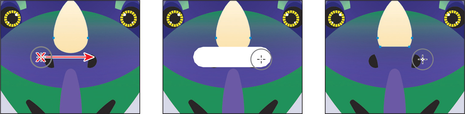
Press the spacebar to access the Hand tool, and drag in the document window to see the partially complete dinosaur to the right.
With the Selection tool (
) selected, click the cream-colored nose horn.Choose View > Zoom In a few times to see more detail.
Double-click the Eraser tool (
) to edit the tool properties. In the Eraser Tool Options dialog box, change Size to 20 pt to make the eraser smaller. Click OK.
With the Eraser tool (
) selected, move the pointer to where you see the red “X” in the first part of the following figure. Press the Shift key, and drag straight across to the right. Release the mouse button and then the Shift key.If nothing is erased, try again. Also, it may look like you erased other parts of the shape, but if nothing else was selected, you didn’t.
Choose File > Save.
Assemble the first dinosaur
To complete the dinosaur you see, you’ll drag and position the artwork you have worked on to this point.
Choose View > Fit Artboard In Window.
With the Selection tool (
) selected, drag the purple shape onto the beak of the dinosaur.Drag the green group of shapes onto the head (see the following figure).
Drag the purple frill onto the purple circle behind the head.
If the purple frill covers any of the artwork, click Arrange toward the bottom of the Properties panel, and choose Send Backward a few times until it looks like the figure.
Creating a compound path
Compound paths let you use a vector object to cut a hole in another vector object. If you were to select two vector objects, the “cutting” object is the top object. Whenever I think of a compound path, I think of a doughnut shape created from two circles. Holes appear where paths overlap. A compound path is like a group, and the individual objects in the compound path can still be edited or released (if you don’t want them to be a compound path anymore).
Next, you’ll create a compound path to provide some art for a dinosaur’s eyes.
Choose 2 Dino 2 from the Artboard Navigation menu in the lower-left corner of the Document window.
With the Selection tool (
) selected, select the gray circle on the far left of the artboard, and drag it into the center of the larger yellow circle to its right.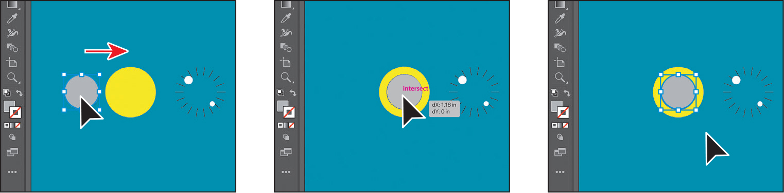
Smart Guides help you align the circles. You can also select the two circles and align them to each other using the Align options in the Properties panel.
Drag across the gray circle and yellow circle to select both.
TipYou can still edit the original shapes in a compound path like this one. To edit them, select each shape individually with the Direct Selection tool (
), or double-click the compound path with the Selection tool, to enter Isolation mode and select individual shapes.Choose Object > Compound Path > Make, and leave the artwork selected.

You can now see that the gray circle has seemingly disappeared, and you can see through the yellow shape to the aqua background shape. The gray circle “punched” a hole in the yellow shape. With the shape still selected, you should see “Compound Path” at the top of the Properties panel to the right.
Drag the group of lines just to the right of the yellow shape into the center of the yellow shape.
The group of lines should be on top of the yellow circle. If it isn’t, choose Object > Arrange > Bring To Front.

Drag across the eye shapes to select them.
Choose Object > Group.
Choose Select > Deselect and then choose File > Save.
Combining shapes
Creating more complex shapes from simpler shapes can be easier than creating them with drawing tools like the Pen tool. In Illustrator, you can combine vector objects in different ways. The resulting paths or shapes differ depending on the method you use to combine the paths. In this section, you’ll explore a few of the more widely used methods for combining shapes.
Start by creating a shape
Before you can jump into combining shapes, you’ll create a triangle. Then you’ll combine it with a few other shapes that are already there. Those shapes will then become the last part of the dinosaur. Before you create the triangle, you’ll swap the selected fill and stroke colors so that the fill becomes the stroke for the new shape you make.
To swap the fill and the stroke of the shape so that the fill becomes the stroke, click the Swap Fill And Stroke button toward the bottom of the toolbar.
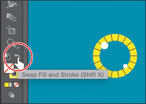
Having a stroke on the shape you are about to draw, rather than a fill, will make it easier to see a gray guide path.
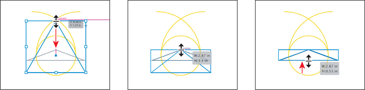
Press and hold on the Rectangle tool and select the Polygon tool in the toolbar.
To the right of the eye shapes, in the middle of the artboard, you’ll see a few yellow shapes. Starting in the center of the yellow circle, drag to create a polygon. While dragging, press the down arrow a few times until the shape has three sides (triangle). Drag until the shape is as wide as the gray triangle guide, press the Shift key to straighten it, and release the mouse button and then the key.

Drag the top edge of the triangle down to snap to the guide triangle, and drag the bottom bounding point up to snap to the same guide triangle.
Working with the Shape Builder tool
The first method you’ll learn for combining shapes involves working with the Shape Builder tool (![]() ). This tool allows you to visually and intuitively merge, delete, fill, and edit overlapping shapes and paths directly in the artwork. Using the Shape Builder tool, you’ll create a more complex shape for another dinosaur head from a series of simpler shapes you create.
). This tool allows you to visually and intuitively merge, delete, fill, and edit overlapping shapes and paths directly in the artwork. Using the Shape Builder tool, you’ll create a more complex shape for another dinosaur head from a series of simpler shapes you create.
Select the Selection tool (
), and drag across the yellow paths and the shape you made. The gray guide path for the triangle is locked, so it won’t be selected.
Change the stroke weight to 5 pt in the Properties panel. Change the stroke color to the color named Orange to make it easier to see.
To edit shapes with the Shape Builder tool (
 ), they need to be selected. Using the Shape Builder tool, you will now combine, delete, and paint these simple shapes to create a single shape. Tip
You can also press the Shift key, and drag a marquee across a series of shapes to combine them. Pressing Shift+Option (macOS) or Shift+Alt (Windows) and dragging a marquee across selected shapes with the Shape Builder tool (
) allows you to delete a series of shapes within the marquee.Select the Shape Builder tool (
) in the toolbar. Move the pointer off the left side of the shapes, and drag to the right. Release the mouse button to combine the shapes.
When you select the Shape Builder tool, the overlapping shapes are temporarily divided into separate objects. As you drag from one part to another, a red outline appears, showing you the resulting shape when the shapes are merged together. The red outline, in this case, is challenging to see since it’s red on an orange stroke.
Next, you’ll delete a few shapes. You may want to zoom in to the shapes.
NoteWhen you position the pointer over the shapes, make sure you see the mesh within those shapes before clicking to delete.
With the shapes still selected, hold down the Option (macOS) or Alt (Windows) key. Notice that, with the modifier key held down, the pointer shows a minus sign (
 ). Click in the middle of the shape on the far left, not the stroke, to delete it. Zoom in if you need. Refer to the figure to see which shape to remove.
Move the pointer below the shapes. Hold down the Option (macOS) or Alt (Windows) key, and drag through the rest of the bottom shapes. Release the mouse button and then the key to remove those shapes.
Option-drag (macOS) or Alt-drag (Windows) across the two curved paths to delete them. Refer to the figure to see what to remove.

Select the Selection tool. To swap the fill and the stroke of the shape so that the stroke becomes the fill, click the Swap Fill And Stroke button toward the bottom of the toolbar.

Assemble the second dinosaur
To complete the second dinosaur, you’ll drag and position the artwork you have worked on to this point.
Choose View > Fit Artboard In Window.
With the Selection tool (
) selected, drag the yellow eye into place on the dinosaur and the orange shape onto the nose. Don’t worry about exact positioning. Leave the last orange shape selected.Choose View > Zoom In a few times to zoom in to the dinosaur.

To arrange the orange shape behind the other artwork on the nose, click Arrange in the Properties panel, and choose Send Backward as many times as necessary. I had to choose it three times.

Click the yellow circle around the eye, and to resize it, press the Shift key, and drag a corner. Release the mouse button and then the key. Drag it into place.

To make a copy, Option-drag (macOS) or Alt-drag (Windows) the eye to the other side. Release the mouse button and then the key.

Choose Select > Deselect, and then choose File > Save.
Combining objects using Pathfinder effects
Pathfinder effects, found in the Properties panel or the Pathfinder panel (Window > Pathfinder), are another way to combine shapes in a variety of ways. By default, when a Pathfinder effect such as Unite is applied, the original objects selected are permanently transformed.
Choose 3 Dino 3 from the Artboard Navigation menu in the lower-left corner of the Document window.

With the Selection tool (
) selected, drag across the three ellipses with the black strokes to select them all.You need to create a combined shape for the dinosaur head to the right. You will use the Properties panel and those shapes to create the final artwork.
NoteThe Unite button in the Properties panel produces a similar result as the Shape Builder tool by combining multiple shapes into one.
With the shapes selected, in the Pathfinder section of the Properties panel on the right, click the Unite button (
 ) to permanently combine the three shapes into a path.
Choose Edit > Undo Add to undo the Unite command and bring all of the shapes back. Leave them selected.
![]() Tip
Tip
Clicking More Options (![]() ) in the Pathfinder section of the Properties panel will reveal the Pathfinder panel, which has more options.
) in the Pathfinder section of the Properties panel will reveal the Pathfinder panel, which has more options.
Understanding shape modes
In the previous section, the pathfinders made a permanent change to the shapes. With shapes selected, Option-clicking (macOS) or Alt-clicking (Windows) any of the default set of pathfinders showing in the Properties panel creates a compound shape rather than a standard shape (path). The original underlying objects of compound shapes are preserved. As a result, you can still select each original object within a compound shape. Using a shape mode to create a compound shape can be useful if you think that you may want to retrieve the original shapes at a later time.
With the shapes still selected, press the Option (macOS) or Alt (Windows) key, and click the Unite button (
) in the Properties panel.
This creates a compound shape that traces the outline of what’s left after the shapes are combined. You’ll still be able to edit the original shapes separately.
Choose Select > Deselect to see the final shape.
TipTo edit the original shapes in a compound shape like this one, you can also select them individually with the Direct Selection tool (
).With the Selection tool, double-click the black stroke of the shape to enter Isolation mode.
You double-clicked the stroke of the shape and not anywhere in the shapes because they do not have a fill.
Click the edge of the ellipse at the top or drag across the path to select it.
Drag the selected ellipse straight down from the blue dot in the center, if you see it, or from the path stroke. As you drag, press the Shift key. When in position, release the mouse button and then the Shift key.

Press the Escape key to exit Isolation mode.
You will now expand the artwork appearance. Expanding the appearance of a compound shape maintains the shape of the compound object, but you can no longer select or edit the original objects. You will typically expand an object when you want to modify the appearance attributes and other properties of specific elements within it.
Click away from the shape to deselect it and then click to select it again. That way the entire object is selected, and not just the one shape.
Choose Object > Expand Appearance.
The Pathfinder effect is now permanent and the shapes are a single shape.
Change the Fill color in the Properties panel to an aqua.
Change the stroke weight to 0.

Reshaping a path
In Lesson 3 you learned about creating shapes and paths (lines). You can use the Reshape tool to stretch parts of a path without distorting its overall shape. In this section, you’ll change the shape of a line, giving it a bit of curve, so you can finish the nose of one of the dinosaurs.
Make sure the Smart Guides are on (View > Smart Guides).
With the Selection tool (
) selected, click the light green path in the middle of the artboard.To make it easier to see, press Command and + (macOS) or Ctrl and + (Windows) a few times to zoom in.
 Note
NoteYou may want to press the Escape key to hide the extra tools menu.
Click Edit Toolbar (
) at the bottom of the toolbar. Scroll in the menu that appears, and drag the Reshape tool ( ) onto the Rotate tool (
 ) in the toolbar on the left to add it to the list of tools. Note
You can use the Reshape tool on a closed path, like a square or circle, but if the entire path is selected, the Reshape tool will add anchor points and move the path.
With the Reshape tool (
) selected, move the pointer over the middle of the path. When the pointer changes ( ), drag to the left to add an anchor point and reshape the path.
The Reshape tool can be used to drag an existing anchor point or path segment. If you drag from an existing path segment, an anchor point is created.
NoteOnly selected anchor points are adjusted when dragging with the Reshape tool.
Move the pointer over the top anchor point of the path, and drag it to the left a little. Leave the path selected.

Using the Width tool
Not only can you adjust the weight of a stroke, as you did in Lesson 3, but you can alter regular stroke widths either by using the Width tool (![]() ) or by applying width profiles to the stroke. This allows you to create a variable width along the stroke of a path. Next, you will use the Width tool to adjust the path you just reshaped.
) or by applying width profiles to the stroke. This allows you to create a variable width along the stroke of a path. Next, you will use the Width tool to adjust the path you just reshaped.
![]() Tip
Tip
You can drag one width point on top of another width point to create a discontinuous width point. If you double-click a discontinuous width point, the Width Point Edit dialog box allows you to edit both width points.
Select the Width tool (
 ) in the toolbar. Move the pointer over the middle of the path you just reshaped, and notice that the pointer has a plus symbol next to it (
 ) when it’s positioned over the path. If you were to drag, you would edit the width of the stroke. Drag away from the line, to the right. Notice that, as you drag, you are stretching the stroke to the left and right equally. Release the mouse button when the measurement label shows Width at approximately 0.4 in.
You just created a variable stroke on a path, not a shape with a fill. The new point on the original path is called the width point. The lines extending from the width point are the handles.
 Tip
TipIf you select a width point by clicking it, you can press Delete to remove it. When there is only one width point on a stroke, removing that point removes the width completely.
Click in an empty area of the artboard to deselect the point.

Move the pointer anywhere over the path, and the width point you just created will appear (an arrow is pointing to it).
Move the pointer over the original width point, and when you see lines extending from it and the pointer changes (
 ), drag it up and down to see the effect on the path. See the last part of the following figure for where it should approximately land.
In addition to dragging to reposition a width point, you can double-click and enter values in a dialog box. That’s what you’ll do next.
Move the pointer over the top anchor point of the path, and notice that the pointer has a wavy line next to it (
 ) and the word “anchor” appears (see the first part of the following figure). Double-click the point to create a new width point and to open the Width Point Edit dialog box. Tip
You can select a width point and Option-drag (macOS) or Alt-drag (Windows) one of the width point handles to change one side of the stroke width.
TipAfter defining the stroke width, you can save the variable width as a profile that you can reuse later from the Stroke panel or the Control panel. To learn more about variable-width profiles, search for “Apply stroke on an object” in Illustrator Help (Help > Illustrator Help).
In the Width Point Edit dialog box, change Total Width to 0 in, and click OK.

The Width Point Edit dialog box allows you to adjust the length of the width point handles, together or separately, with more precision. Also, if you select the Adjust Adjoining Width Points option, any changes you make to the selected width point affect neighboring width points as well.
Move the pointer over the bottom anchor point of the path, and double-click. In the Width Point Edit dialog box, change Total Width to 0 in, and click OK.

Move the pointer over the original width point. When the width point handles appear, drag one of them away from the center of the path to make it a little wider. Leave the path selected for the next section.

Change the Stroke color in the Properties panel to black.
Assemble the last dinosaur
To complete the dinosaur you see, you’ll drag and position the artwork you have worked on to this point.
Choose View > Fit Artboard In Window.

With the Selection tool (
) selected, drag the aqua dinosaur head shape and the path you reshaped onto the dinosaur to the right. Leave the black reshaped path selected.Choose View > Zoom In a few times to zoom in to the dinosaur.
Shift-drag the corner of the black path to make it smaller. Notice that the stroke weight is still the same even though the line is smaller. This happens by default.
Change the stroke weight in the Properties panel to 19.

Drag it into the position you see in the first part of the following figure.
To make a copy of the reshaped path, Option-drag (macOS) or Alt-drag (Windows) it to the other side. Release the mouse button and then the key.
In the Properties panel, click Flip Horizontally to flip the shape.

Choose View > Fit All In Window.
Choose File > Save, and then choose File > Close.

Review questions
1 Name two ways you can combine several shapes into one.
2 What is the difference between the Scissors tool (![]() ) and the Knife tool (
) and the Knife tool (![]() )?
)?
3 How can you erase with the Eraser tool (![]() ) in a straight line?
) in a straight line?
4 What is the main difference between shape modes and Pathfinder effects in the Properties panel or Pathfinder panel?
5 Why would you outline strokes?
Review answers
1 Using the Shape Builder tool (![]() ), you can visually and intuitively merge, delete, fill, and edit overlapping shapes and paths directly in the artwork. You can also use the Pathfinder effects, which can be found in the Properties panel, the Effects menu (not mentioned in this lesson), or the Pathfinder panel, to create new shapes out of overlapping objects.
), you can visually and intuitively merge, delete, fill, and edit overlapping shapes and paths directly in the artwork. You can also use the Pathfinder effects, which can be found in the Properties panel, the Effects menu (not mentioned in this lesson), or the Pathfinder panel, to create new shapes out of overlapping objects.
2 The Scissors tool (![]() ) is meant to split a path, graphics frame, or empty text frame at an anchor point or along a segment. The Knife tool (
) is meant to split a path, graphics frame, or empty text frame at an anchor point or along a segment. The Knife tool (![]() ) cuts objects along a path you draw with the tool, dividing objects. When you cut a shape with the Scissors tool, it becomes an open path. When you cut a shape with the Knife tool, the resulting shapes become closed paths.
) cuts objects along a path you draw with the tool, dividing objects. When you cut a shape with the Scissors tool, it becomes an open path. When you cut a shape with the Knife tool, the resulting shapes become closed paths.
3 To erase in a straight line with the Eraser tool (![]() ), press and hold the Shift key before you begin dragging with the Eraser tool.
), press and hold the Shift key before you begin dragging with the Eraser tool.
4 In the Properties panel, when a shape mode (such as Unite) is applied, the original objects selected are permanently transformed, but you can hold down the Option (macOS) or Alt (Windows) key and the original underlying objects are preserved. When a Pathfinder effect (such as Merge) is applied, the original objects selected are permanently transformed.
5 A path, like a line, can show a stroke color but not a fill color by default. If you create a line in Illustrator and want to apply both a stroke and a fill, you can outline the stroke, which converts the line into a closed shape (or compound path).