3. Using Shapes to Create Artwork for a Postcard
Lesson overview
In this lesson, you’ll learn how to do the following:
Create a new document.
Use tools and commands to create a variety of shapes.
Understand Live Shapes.
Create rounded corners.
Work with drawing modes.
Use Image Trace to create shapes.
Simplify paths.

This lesson will take about 60 minutes to complete. To get the lesson files used in this chapter, download them from the web page for this book at adobepress.com/IllustratorCIB2022. For more information, see “Accessing the lesson files and Web Edition” in the Getting Started section at the beginning of this book.

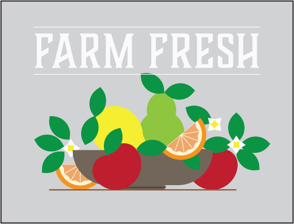
Basic shapes are essential to creating Illustrator artwork. In this lesson, you’ll create a new document and then use the shape tools to create and edit a series of shapes for a postcard.
Starting the lesson
In this lesson, you’ll explore the different methods for creating artwork using the shape tools and other methods to add artwork to a postcard for a farmers market.
![]() Note
Note
If you have not already downloaded the project files for this lesson to your computer from your Account page, make sure to do so now. See the “Getting Started” section at the beginning of the book.
To ensure that the tools function and the defaults are set exactly as described in this lesson, delete or deactivate (by renaming) the Adobe Illustrator preferences file. See “Restoring default preferences” in the “Getting Started” section at the beginning of the book.
Start Adobe Illustrator.
Choose File > Open. Locate the file named L3_end.ai, which is in the Lessons > Lesson03 folder that you copied onto your hard disk, and click Open.
This file contains the finished illustrations that you’ll create in this lesson.
Choose View > Fit All In Window; leave the file open for reference, or choose File > Close.
Creating a new document
To start, you’ll create a new document for the postcard that you’ll add artwork to.
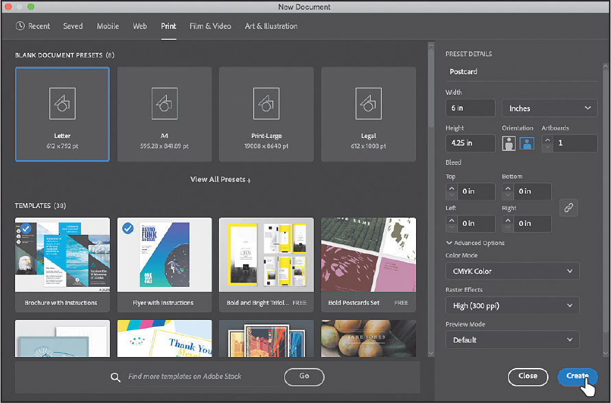
Choose File > New to create a new document. In the New Document dialog box, change the following options:
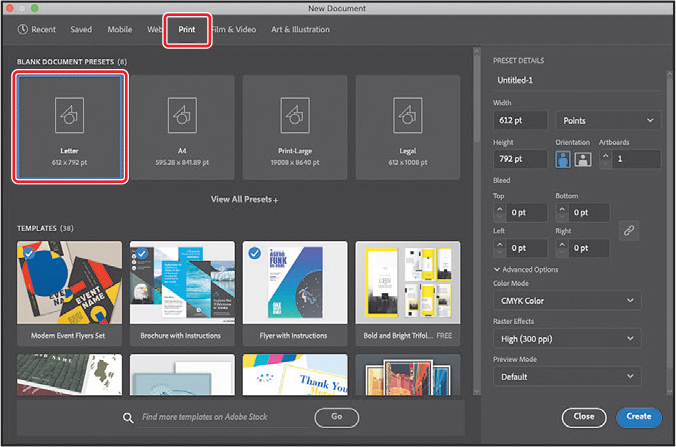
Select the Print category at the top of the dialog box.
Select the Letter blank document preset, if it isn’t already selected.
You can set up a document for different kinds of output, such as print, web, video, and more, by choosing a category. For example, if you are designing a web page mockup, you can select the Web category and select a document preset (size). The document will be set with the units in points (most likely), the color mode as CMYK, and the raster effects to High (300 ppi)—all optimal settings for a print document.
On the right side of the dialog box, in the Preset Details area, change the following:
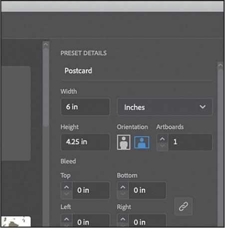
Enter a name for the document in the blank space under Preset Details: Postcard.
The name will become the name of the Illustrator file when you save it later.
Units: Choose Inches from the units menu to the right of the Width field.
Width: Select the Width value, and type 6.
Height: Select the Height value, and type 4.25.
Orientation: Landscape (
 ).
).Artboards: 1 (the default setting).
You’ll learn about the Bleed option shortly. At the bottom of the Preset Details section on the right side of the New Document dialog box, you will also see Advanced Options and More Settings (you may need to scroll to see it). They contain more settings for document creation that you can explore on your own.
Click Create to create a new document.
With the document open in Illustrator, now you’ll save it.
Choose File > Save As. If the Cloud Document dialog box opens, click Save On Your Computer to save the document locally.
In the Save As dialog box that opens, make sure that the name of the file is Postcard.ai, and save it in the Lessons > Lesson03 folder. Leave Adobe Illustrator (ai) chosen from the Format menu (macOS) or Adobe Illustrator (*.AI) chosen from the Save As Type menu (Windows), and click Save.
Adobe Illustrator (.ai) is called a native format and is your working file. That means it preserves all Illustrator data so you can edit everything later.
 Tip
TipIf you want to learn more about these options, search for “Save artwork” in Illustrator Help (Help > Illustrator Help).
In the Illustrator Options dialog box that appears, leave the options at their default settings, and click OK.
The Illustrator Options dialog box is full of options for saving the Illustrator document, from specifying a version for saving to embedding any files that are linked to the document.
Choose Window > Workspace > Essentials (if it’s not already selected).
Choose Window > Workspace > Reset Essentials to reset the panels and settings for the Essentials workspace.
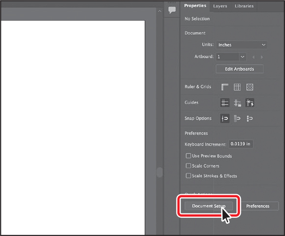
Click the Document Setup button in the Properties panel (Window > Properties).
The Document Setup dialog box is where you can change document options like units, bleeds, and more after a document is created. You will typically add bleed to artboards for printed artwork that needs to be printed all the way to the edge of the paper. Bleed is the term used for the area that extends beyond the edge of the printed page, and it ensures that no white edges show up on the final trimmed page.
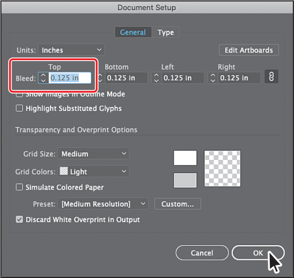
In the Bleed section of the Document Setup dialog box, change the value in the Top field to 0.125 in, either by clicking the up arrow button to the left of the field once or by typing the value, which should make all four fields change. Click OK.
Choose View > Fit Artboard In Window to fit the artboard (page) in the Document window.
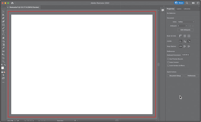
The area between the red line around the artboard and the edge of the white artboard is the bleed area.
Working with basic shapes
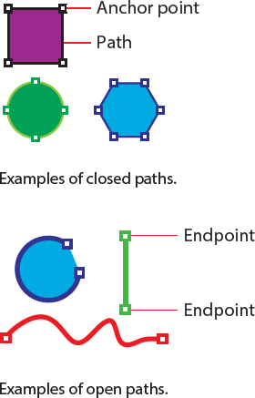
In the first part of this lesson, you’ll create a series of basic shapes, including rectangles, ellipses, and polygons. Shapes you create are composed of anchor points with paths connecting the anchor points. A basic square, for instance, is composed of four anchor points on the corners with paths connecting those anchor points (see the upper figure at right). A shape is referred to as a closed path because the ends of the path are connected.
A path, like a line, can also be open. An open path has distinct anchor points on each end, called endpoints (see the figure at right). You can fill open and closed paths with color, gradients, or patterns.
Creating rectangles
You’ll start this lesson by creating a bowl to contain fruit. You’ll build the bowl from a few rectangles, and you’ll explore creating them using two distinct methods.
Select the Rectangle tool (
 ) in the toolbar on the left.
First we’ll create the larger rectangle that will be the main body of the bowl.
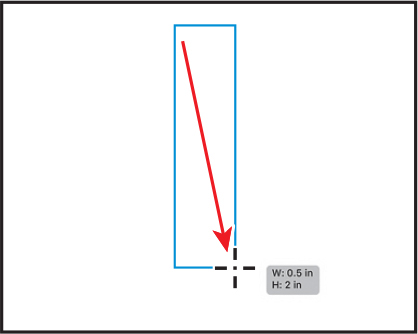
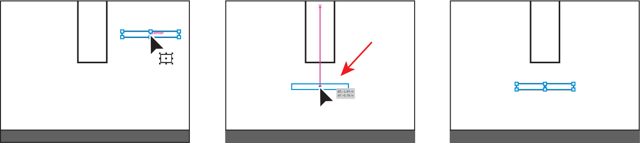
Move the pointer into the artboard. Press the mouse button, and drag down and to the right to create a rectangle that is taller than it is wider. Release the mouse button. Don’t worry about the size right now. You’ll adjust it shortly.
As you drag to create shapes, the tool tip that appears next to the pointer is called the measurement label and is part of Smart Guides (View > Smart Guides). It shows the width and height of the shape as you draw.
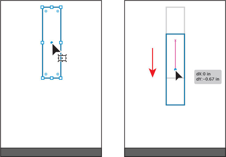
Move the pointer over the small blue dot in the center of the rectangle (called the center point widget). When the pointer changes (
 ), drag the shape into the bottom half of the artboard, roughly centered horizontally.
Next, you’ll create a smaller rectangle to serve as the base of the bowl.
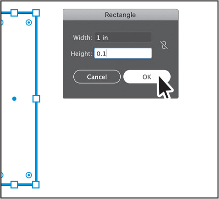
With the Rectangle tool still selected, click anywhere in the document to open the Rectangle dialog box. Change the Width to 1 inch and the Height to 0.1 inches. Click OK to create a new rectangle.
Creating a rectangle with the Rectangle dialog box is useful when you know the size of the shape you need. For most drawing tools, you can either draw with the tool or click to create a shape of a specific size.
 Note
NoteSince the rectangle is small, it may be challenging to drag from the center point. As you go through the lessons, you’ll zoom in and out to make it easier to select things.
Move the pointer over the center point widget, and drag the rectangle below the first rectangle.
You’ll move both shapes into their final positions shortly.
Editing rectangles
All of the shape tools, except for the Star tool and Flare tool, create Live Shapes. Live Shapes have attributes such as width, height, rotation, and corner radius that are editable without switching from the drawing tool you are using.
With two rectangles created, you’ll make some changes to the first.
Select the Selection tool (
 ) in the toolbar.
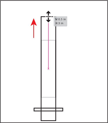
Click in the larger rectangle you created to select it. Drag up from the middle point on the top of the rectangle to make it taller. As you drag, press the Option (macOS) or Alt (Windows) key to resize the top and bottom together. When you see a height of approximately 3 inches in the measurement label (the gray tool tip next to the pointer), release the mouse button and then the key.
To rotate the shape, move the pointer just off of a corner on the shape. When you see rotate arrows (
 ), drag clockwise to rotate the shape. As you drag, press the Shift key to constrain the rotation to increments of 45 degrees. When an angle of 270 shows in the measurement label, release the mouse button and then the key. Leave the shape selected.
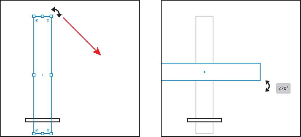
In the Transform section of the Properties panel on the right, make sure Maintain Width And Height Proportions to the right of Width (W:) and Height (H:) is deselected (it looks like this:
 ). Select the Height (H:) value, and type 0.75. Press Return or Enter to accept the change.
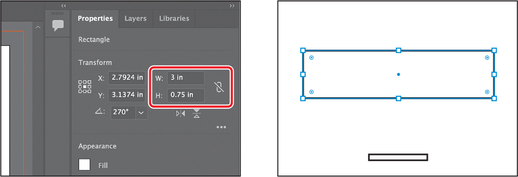
The Maintain Width And Height Proportions setting is useful when you change the height or the width and want the other value to change proportionally. The options in the Transform section of the Properties panel help transform selected shapes and other artwork precisely. You’ll learn more about those options in Lesson 5, “Transforming Artwork.”
By default, shapes are filled with white and have a black stroke (border). Next, you’ll change the color of the larger rectangle to brown to suggest a bowl made of dark wood, like walnut.
Click the Fill color box in the Properties panel on the right. In the panel that opens, make sure that the Swatches option (
 ) is selected at the top. Select a brown color to fill the rectangle. I chose a brown with a tool tip that shows “C=50 M=50 Y=60 K=25” when you hover the pointer over the color.
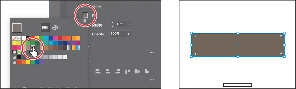
Press the Escape key to hide the Swatches panel before moving on.
Click the Stroke color box in the Properties panel, make sure that the Swatches option (
) is selected, and select None to remove the stroke from the rectangle. Press the Escape key to hide the Swatches panel before moving on.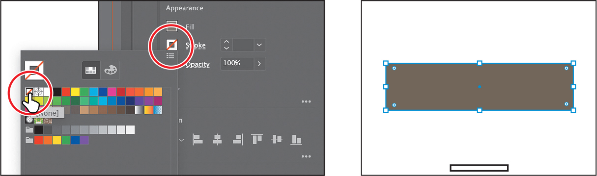
Choose Select > Deselect, and then choose File > Save to save the file.
Rounding corners
The rectangles you created don’t look very much like a bowl. Luckily it’s easy to round off the corners of rectangles to make more interesting—and practical—shapes. In this section, you’ll round all the corners of the smaller rectangle.
Click the smaller rectangle to select it.
Choose View > Zoom In as many times as necessary until you see the Live Corners widgets (
 ) in each corner of the rectangle.
If you are zoomed out far enough, the Live Corners widgets are hidden on the shape.
 Note
NoteIf you drag until you see a red arc, in the next step the value won’t change when you click the up arrow since the maximum is already achieved.
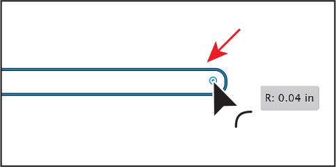
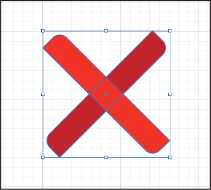
Drag any of the Live Corners widgets (
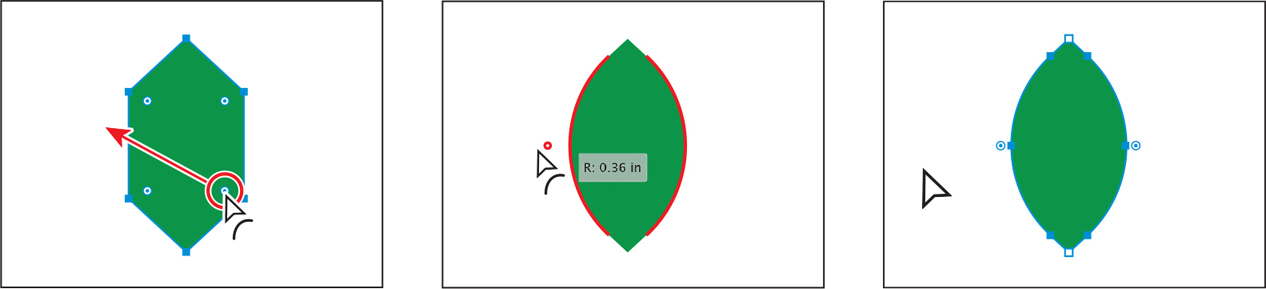
) in the rectangle toward the center to round the corners a little.The more you drag toward the center, the more rounded the corners become. If you drag a Live Corners widget far enough, a red arc appears on the shape, indicating you’ve reached the maximum corner radius.
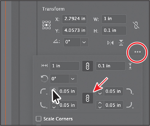
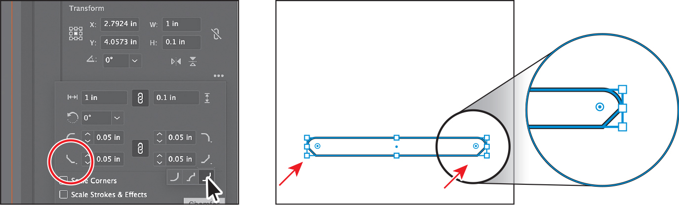
In the Properties panel to the right, click More Options (
 ) in the Transform section to show more options. Ensure that Link Corner Radius Values is on (
 ) (an arrow is pointing to it in the figure), and click the up arrow for any of the Radius values as many times as you can until the value no longer increases (the maximum radius value is achieved). If necessary, click in another field or press the Tab key to see the change to all corners.
Aside from changing the corner radius, you can also change the corner type. You can choose between Round (default), Inverted Round, and Chamfer.
With the options still showing in the Properties panel, click the corner type for each of the bottom corners, and choose Chamfer.
TipYou can also double-click a Live Corners widget in a shape to open the Transform panel as a free-floating panel.
Press the Escape key to close the options panel.
Click the Fill color box in the Properties panel on the right. In the panel that opens, make sure that the Swatches option (
) is selected at the top. Select a brown color to fill the rectangle. We chose a brown that is darker than the brown of the larger rectangle.Click the Stroke color box in the Properties panel, make sure that the Swatches option (
) is selected, and select None to remove the stroke from the rectangle. NoteYou should be getting used to hiding panels, like stroke color, first—then you can access the menu items.
Choose Select > Deselect.
Rounding individual corners
Next, you’ll explore rounding the individual corners of a rectangle.
Choose View > Fit Artboard In Window.
Click the larger rectangle to select it.
The Live Corners widgets (
) should be showing in the corners of the shape.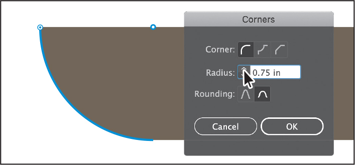 Tip
TipYou can Option-click (macOS) or Alt-click (Windows) a Live Corners widget in a shape to cycle through the different corner types.
Select the Direct Selection tool (
 ) in the toolbar. With the shape still selected, double-click the lower-left Live Corners widget (). In the Corners dialog box, click the up arrow for the Radius value until the value stops changing (the maximum value is reached). Click OK.
Notice that only one corner changed. The Corners dialog box allows you to also select an extra option called Rounding to set absolute versus relative rounding (see the previous figure). Absolute (
 ) means the rounded corner is exactly the radius value. Relative (
 ) bases the radius value on the angle of the corner point.
Click the lower-right Live Corners widget (
) to select just that one Live Corners widget. See the first part of the following figure.Drag that widget (
) to round the corner until you see the red color on the path, indicating that the corner is as round as it can get.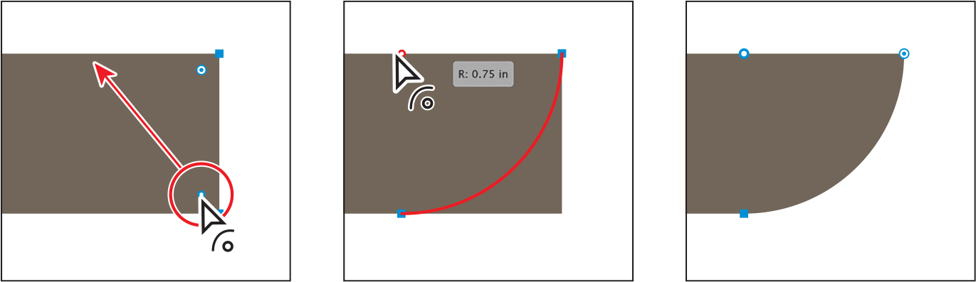
Select the Selection tool (
) in the toolbar, and drag the larger rectangle so that it touches the smaller rectangle and is aligned horizontally with the smaller rectangle.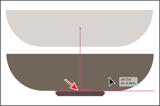
A magenta line will appear in the center of both shapes when they are aligned.
Choose Select > Deselect, and then choose File > Save.
Drawing on a grid for alignment
A grid is a series of horizontal and vertical lines for you to create artwork on. The grid appears behind your artwork in the illustration window. It does not print.
To show or hide the grid, choose View > Show Grid or View > Hide Grid.
To snap objects to gridlines, choose View > Snap To Grid, select the object you want to move, and drag it to the desired location.
When the object’s boundary comes within 2 pixels of a gridline, it snaps to the line.
To specify the spacing between gridlines, grid style (lines or dots), grid color, or whether grids appear in the front or back of artwork, choose Illustrator > Preferences > Guides & Grid (macOS) or Edit > Preferences > Guides & Grid (Windows).
—From Illustrator Hel
Creating and editing ellipses
Next, you’ll create a few ellipses with the Ellipse tool (![]() ) to make a pear. The Ellipse tool can be used to create ellipses and perfect circles.
) to make a pear. The Ellipse tool can be used to create ellipses and perfect circles.
Press and hold the mouse button on the Rectangle tool (
) in the toolbar, and select the Ellipse tool ( ).
).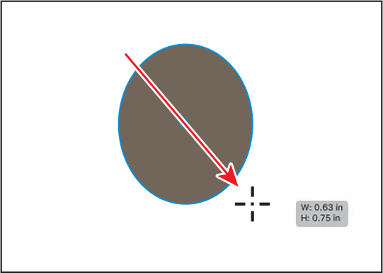
Above the bowl, on the left side of the artboard, drag to make an ellipse with an approximate width of 0.6 inches and a height of 0.75 inches.
Now you’ll draw a perfect circle and start drawing so it’s perfectly aligned with the center of the ellipse you just made. Drawing it where you want it, instead of drawing it and moving it, saves you steps.
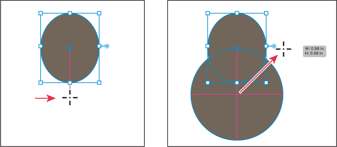
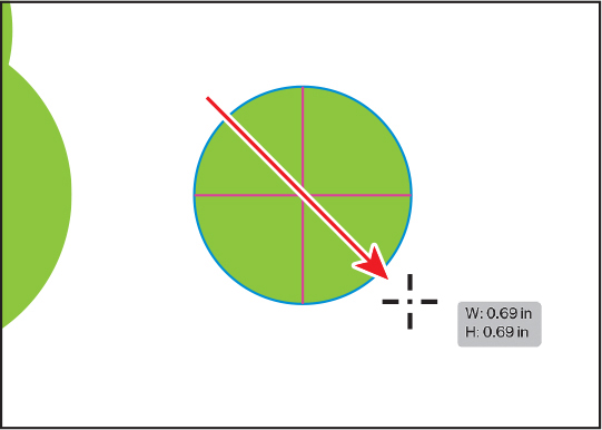
With the Ellipse tool still selected, move the pointer just below the edge of the ellipse, aligned with the center of it. A magenta guide will appear when the pointer is aligned with the horizontal center (see the first part of the following figure).
TipThe Shift key constrains the ellipse to a perfect circle, and the Option/Alt key lets you draw from the center of the shape.
Now, to draw the shape from the center, press Option+Shift (macOS) or Alt+Shift (Windows), and drag to create a circle that has an approximate width and height of 1 inch. As you drag the pointer, you can tell it’s a perfect circle when magenta crosshairs appears within. Release the mouse button and then the keys.
To keep the shapes together, select the Selection tool (
), and drag across both shapes to select them. Click the Group button in the Quick Actions section of the Properties panel to the right.Grouping treats content like a single object, which makes it easier to move the currently selected artwork. You’ll group other content you create going forward for the same reason.
Click the Fill color box in the Properties panel on the right. In the panel that opens, make sure that the Swatches option (
) is selected at the top. Select a green color to fill the shapes in the group.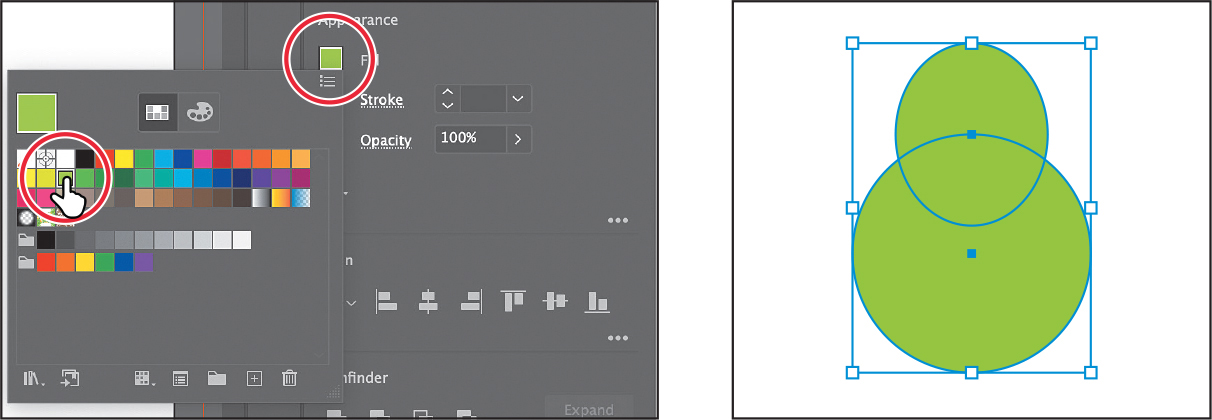
Choose Select > Deselect, and then choose File > Save.
Creating and editing circles
Next, you’ll create three perfect circles with the Ellipse tool (![]() ) to create an apple. For one of those circles, you’ll explore the Live Shapes feature that allows you to create a pie shape.
) to create an apple. For one of those circles, you’ll explore the Live Shapes feature that allows you to create a pie shape.
Select the Ellipse tool (
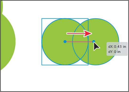
), and, to the right of the pear, press and drag to begin drawing an ellipse. As you drag, press the Shift key to create a perfect circle. When the width and height are both roughly 0.7 inches, release the mouse button and then the Shift key.Without switching to the Selection tool, you can reposition and modify an ellipse with the Ellipse tool, which is what you’ll do next.
With the Ellipse tool selected, move the pointer over the center point of the circle. To make a copy of the circle, press Option (macOS) or Alt (Windows) and drag to the right a little. Release the mouse button and then the key when the circles overlap a bit.
You’ll create one more circle by drawing it. This new circle needs to be as wide as the two circles you already have, so you’ll align the circle with them as you draw it.
Move the pointer over the left edge of the left-most circle. When you see “anchor” next to the pointer, press and drag down and to the right to draw a circle. As you drag, press the Shift key. When it’s as wide as the two circles, a magenta Smart Guide appears on the right edge. Release the mouse button and then the key.
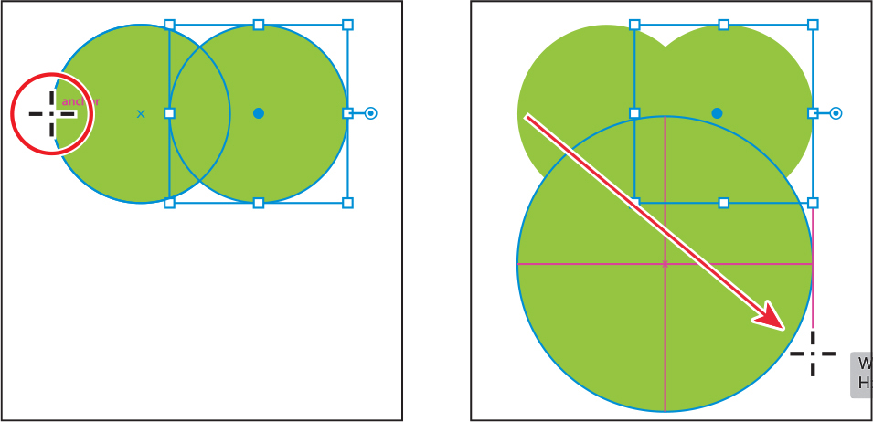
With the ellipse selected, note the pie widget (
 ) projecting from the anchor point on the right side of the ellipse. Drag that pie widget counterclockwise around the top of the ellipse—don’t worry about how far.
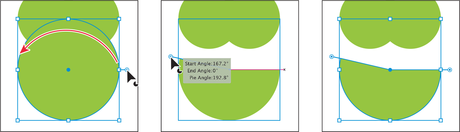
Dragging the pie widget allows you to create a pie shape. After dragging the widget initially and releasing the mouse button, you will then see a second widget. The widget you dragged controls the start angle. The widget that now appears on the right side of the ellipse controls the end angle.
NoteThe figure on the left shows just before choosing 180 from the Pie Start Angle menu.
In the Properties panel to the right, click More Options (
) in the Transform section to show more options. Choose 180° from the Pie Start Angle ( ) menu. Press the Escape key to hide the panel.
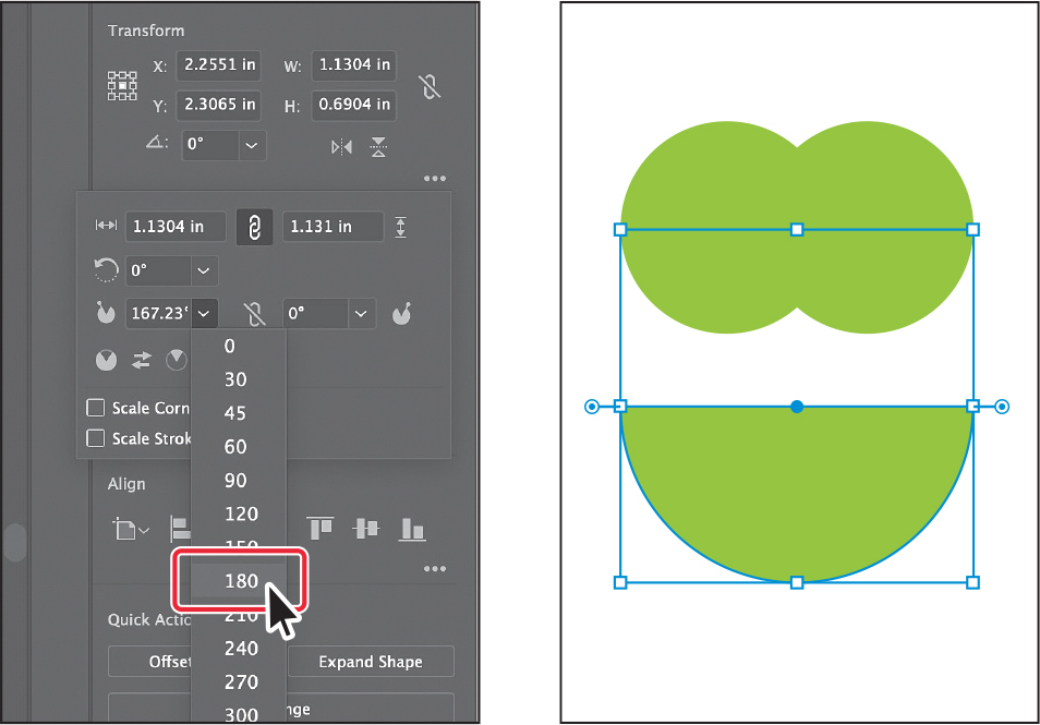
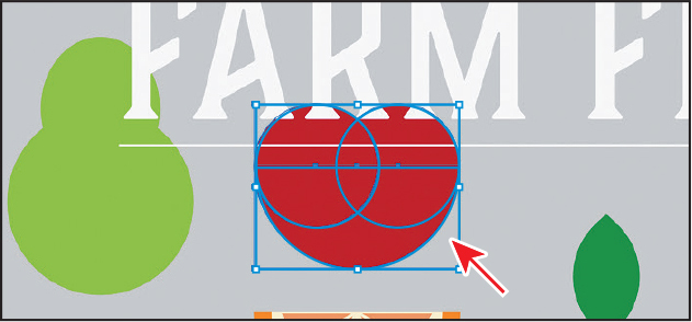
Move the pointer over what was the center of the half ellipse. Drag the shape up over the two smaller circles. When it’s aligned horizontally and vertically centered with the two circles, magenta alignment guides and the word “intersect” will most likely appear next to the pointer.
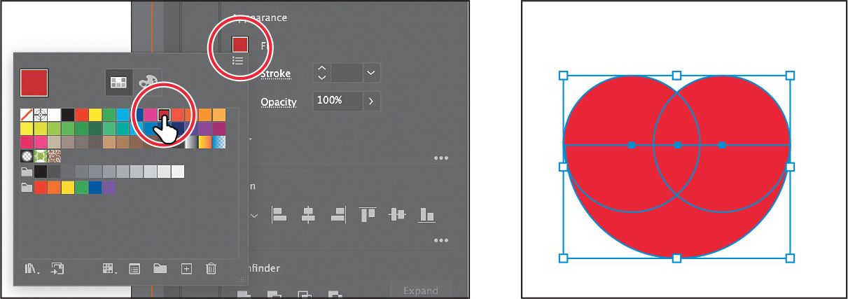
Select the Selection tool in the toolbar, and drag across all three circles to select them.
Click the Fill color in the Properties panel, and make sure that the Swatches option (
) is selected in the panel that appears. Select a red color with a tool tip of “C=15 M=100 Y=90 K=10.”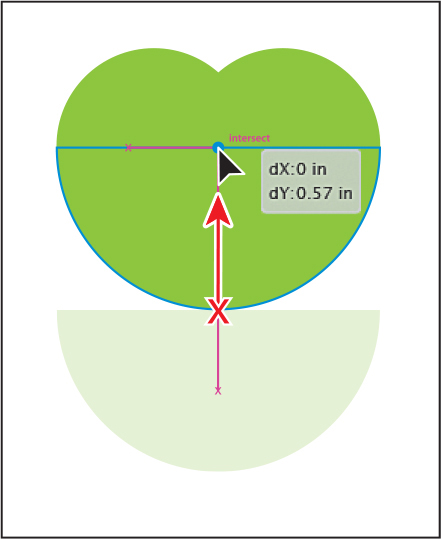
Later in this lesson, you’ll create an orange (the fruit) using a copy of the half circle from the apple as a starting point.
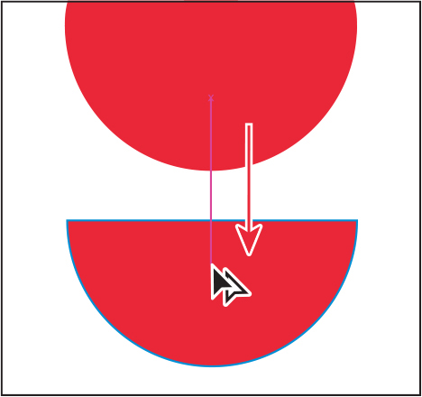
Click in an empty area of the artboard to deselect.
To make a copy of the half circle, press Option (macOS) or Alt (Windows), and drag it into an empty area of the artboard. Release the mouse button and then the key.
Changing stroke width and alignment
Strokes are visible outlines or borders of an object or path. You’ve edited shape fills in this lesson but haven’t done much with strokes aside from removing them. You can easily change the color of a stroke or the weight of a stroke to make it thinner or thicker. You’ll do that next.
With the Selection tool (
) selected, click the smaller rectangle that is the bottom of the bowl.Choose View > Zoom In a few times.
NoteYou may notice in the selected artwork that you see only the corner points of the bounding box. It depends on the zoom level of your document.
Click the word “Stroke” in the Properties panel to open the Stroke panel. In the Stroke panel, change the stroke weight of the selected rectangle to 2. Click the Align Stroke To Inside button (
 ) to align the stroke to the inside edge of the rectangle.
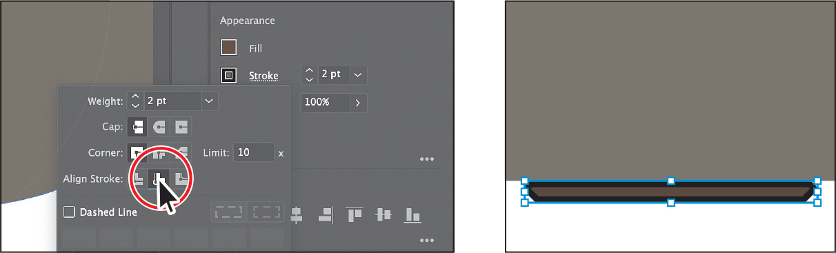
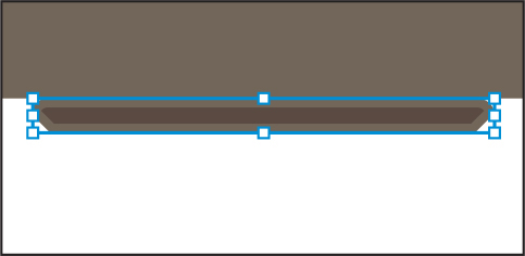
Aligning a stroke to the inside of a shape can be a great way to ensure that the stroke doesn’t overlap the shape above.
Click the Stroke color box in the Properties panel, make sure that the Swatches option (
) is selected, and select a lighter brown color.Choose Select > Deselect.
Creating a polygon
Using the Polygon tool (![]() ), you can create shapes with multiple straight sides. By default, the Polygon tool draws hexagons (a six-sided shape) drawn from the center. Polygons are also Live Shapes, which means attributes such as size, rotation, number of sides, and more remain editable after you create them. Now you’ll create a polygon to make a series of leaves.
), you can create shapes with multiple straight sides. By default, the Polygon tool draws hexagons (a six-sided shape) drawn from the center. Polygons are also Live Shapes, which means attributes such as size, rotation, number of sides, and more remain editable after you create them. Now you’ll create a polygon to make a series of leaves.
Choose View > Fit Artboard In Window to fit the artboard in the Document window.
Press and hold on the Ellipse tool (
) in the toolbar, and select the Polygon tool ( ).
).Choose View > Smart Guides to turn them off.
Move the pointer in a blank area of the artboard. Drag to the right to begin drawing a polygon, but don’t release the mouse button yet. Press the Down Arrow key once to reduce the number of sides on the polygon to five, and don’t release the mouse button yet. Hold down the Shift key to straighten the shape. Release the mouse button and then the key. Leave the shape selected.
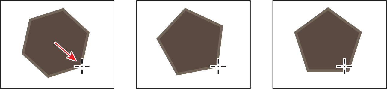
Notice that you didn’t see the gray measurement label (the tool tip), since it’s part of the Smart Guides that you turned off. The magenta alignment guides are also not showing, since the shape is not snapping to other content on the artboard. Smart Guides can be useful in certain situations, such as when more precision is necessary—maybe you want to know how large the shape is—and can be toggled on and off when needed.
To change the fill color, click the Fill color box in the Properties panel, and make sure that the Swatches option (
) is selected in the panel that appears. Select a green color with a tool tip of “C=85 M=10 Y=100 K=10.”Click the Stroke color box in the Properties panel, make sure that the Swatches option (
) is selected, and select None to remove the stroke from the shape.Choose View > Smart Guides to turn them back on.
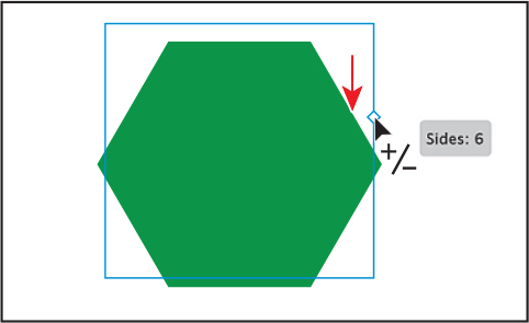
With the Polygon tool still selected, drag the side widget (
 ) on the right side of the bounding box down to change the number of sides to 6.
Editing the polygon
Now you’ll edit the polygon and create a rounded leaf from it.
To rotate the polygon, move the pointer just off a corner of the bounding box around the shape. When the pointer changes to a rotate arrow (
 ), drag counterclockwise. As you drag, press the Shift key to constrain the rotation to multiples of 45 degrees. When you see an angle of 90° in the measurement label next to the pointer, release the mouse button and then the key.
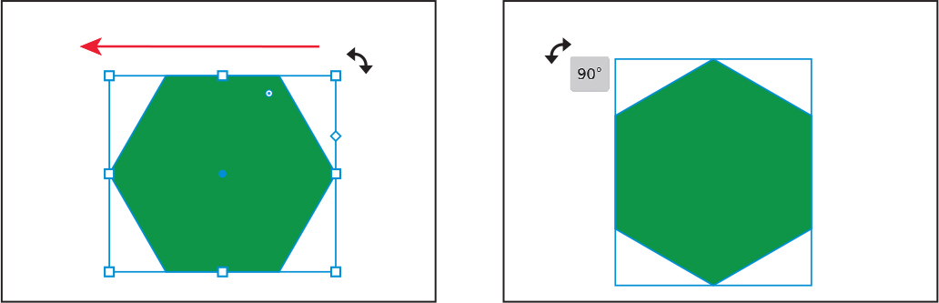
To change the size of the polygon, move the pointer over a corner and drag. As you drag, press the Shift key to change the width and height proportionally (together).
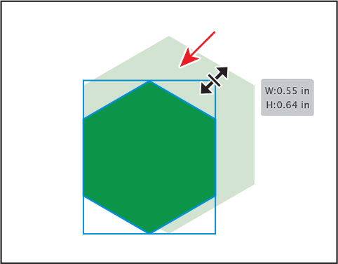
When the measurement label shows a height of approximately 0.65 inches, release the mouse button and then the key. Depending on how big your polygon was to start, you will make it either larger or smaller in this step to match the height we suggest.
In the Transform section of the Properties panel on the right, make sure Maintain Width And Height Proportions to the right of Width (W:) and Height (H:) is deselected (it looks like this:
) so you can change the values independently. Select the Width (W:) value and type 0.35. Press Return or Enter to accept the change.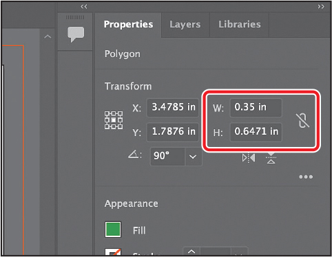
With the leaf shape (polygon) now created, you’ll round some of the corners to make it look a little more natural.
With the polygon selected, choose View > Zoom In a few times to zoom in to it.
If you look at the polygon right now, with the Selection tool (
) selected, you’ll see a single Live Corners widget () in the shape. If you were to drag that widget, all of the corners would be rounded.Select the Direct Selection tool (
) in the toolbar. You should now see Live Corners widgets in each corner. You’ll only round four of the corners.Drag across the four anchor points in the middle of the shape (see the following figure). With those anchors selected, you should see the Live Corners widgets for them.
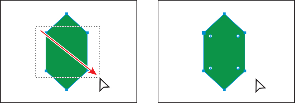
Drag one of the selected Live Corners widgets toward the center of the shape. Keep dragging past the center until you see the red lines, indicating that you can’t round them anymore.
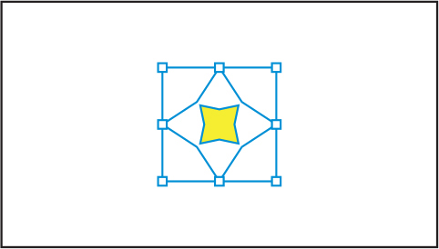
Creating a star
Next, you’ll use the Star tool (![]() ) to create a few stars that will become flowers. Currently, the Star tool doesn’t create Live Shapes, so editing the star after the fact can be more difficult. When drawing with the Star tool, you’ll use keyboard modifiers to get the number of points you want and change the radius of the star’s arms (the length of the arms). Here are the keyboard modifiers you’ll use in this section when drawing the star:
) to create a few stars that will become flowers. Currently, the Star tool doesn’t create Live Shapes, so editing the star after the fact can be more difficult. When drawing with the Star tool, you’ll use keyboard modifiers to get the number of points you want and change the radius of the star’s arms (the length of the arms). Here are the keyboard modifiers you’ll use in this section when drawing the star:
Arrow keys: Pressing the Up Arrow or Down Arrow key adds or removes arms from the star, respectively, as you draw it.
Shift: This straightens the star (constrains it).
Command (macOS) or Ctrl (Windows): Pressing this key and dragging while creating a star allows you to change the radius of the arms of the star (make the arms longer or shorter).
Next you’ll create a star. This will take a few keyboard commands, so don’t release the mouse button until you are told.
Press and hold on the Polygon tool (
) in the toolbar, and select the Star tool ( ). Move the pointer to the right of the leaf.
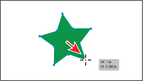 Tip
TipYou can also click in the Document window with the Star tool (
) and edit the options in the Star dialog box instead of drawing it.Press and drag to the right to create a star shape. Notice that as pointer moves, the star changes size and rotates freely. Drag until the measurement label shows a width of about 1 inch and then stop dragging. Don’t release the mouse button!
Press the Down Arrow key once to decrease the number of points on the star to four. Don’t release the mouse button!
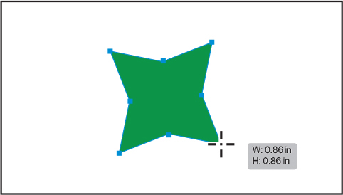
Press Command (macOS) or Ctrl (Windows), and start dragging again, this time toward the center of the star a short distance. This keeps the inner radius constant, making the arms shorter. Drag until the star looks something like the figure and then stop dragging, without releasing the mouse button. Release Command or Ctrl but not the mouse button.
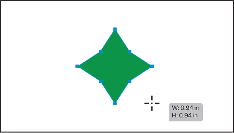
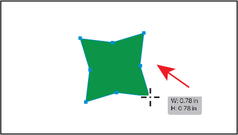
Press the Shift key. When the star straightens out, release the mouse button and then the key.
Editing the star
With the star created, next you’ll transform and copy the star.
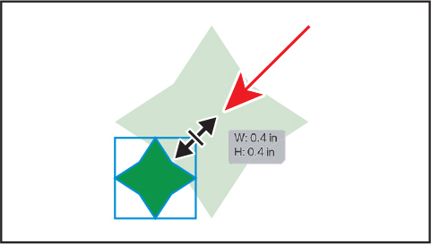
Select the Selection tool (
), press the Shift key, and drag a corner of the star bounding box toward the center. When the star has a width of approximately 0.4 inches, release the mouse button and then the key.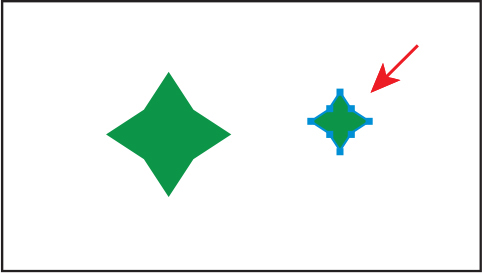
Select the Star tool (
). Press the Shift key, and draw a new star that’s a little smaller than the first. Release the mouse button and then the key.Notice that the new star has the same basic settings as the first star you drew.
To rotate the star, in the Transform section of the Properties panel, change the Rotate value by selecting the value and typing in 45. Press Return or Enter. To scale the star, make sure Maintain Width And Height Proportions to the right of Width (W:) and Height (H:) is selected (it looks like this:
). Select the Height (H:) value, and type 0.14. Press Return or Enter to accept the change.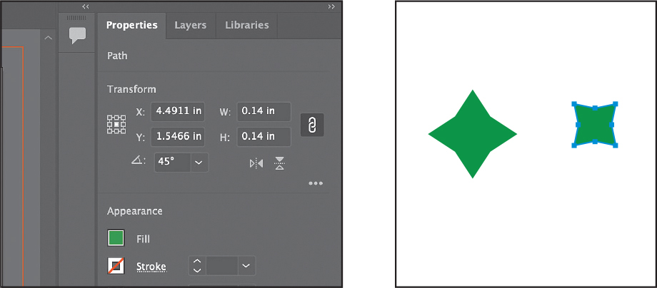
Change the fill color of the smaller star in the Properties panel to a yellow.
Select the Selection tool (
), and drag the smaller star into the center of the larger star.Click in an empty area of the artboard to deselect, and then click the larger star, and change the fill color to white.
Drag across the star shapes to select them, and then click the Group button in the Properties panel to group them together.
Choose File > Save.
Drawing lines
Next, you’ll create a line, known as an open path, with the Line Segment tool. This line will become the surface that the bowl rests on. Lines created with the Line Segment tool are Live Lines, and similar to Live Shapes, they have many editable attributes after they are drawn.
Choose View > Fit Artboard In Window.
Press and hold on the Star tool (
) in the toolbar, and select the Line Segment tool ( ).
).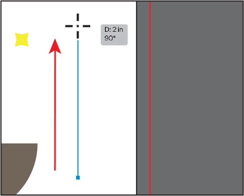
To the right of the bowl, press and drag up to draw a line. As you drag, press the Shift key to constrain the line to a multiple of 45 degrees. Notice the length and angle in the measurement label next to the pointer as you drag. Drag until the line is around 2 inches in length.
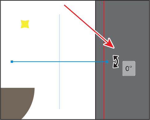
With the new line selected, move the pointer just off the top end. When the pointer changes to a rotate arrow (
 ), press and drag down until you see an angle of 0 (zero) in the measurement label next to the pointer. That will make the line horizontal.
Lines rotate around their center point by default.
Select the Selection tool (
) in the toolbar, and drag the line by the center point to just below the bowl. When it is touching the bottom of the bowl and it is aligned horizontally with the bowl—you’ll see a vertical alignment guide when the line is aligned with the bowl—release the mouse button.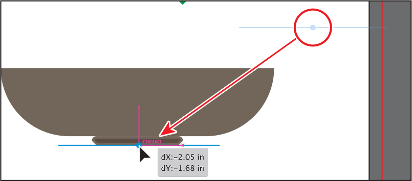
This line represents a table that the bowl is sitting on, so make sure the line touches the bottom of the bowl.
With the line selected, change the stroke weight to 2 pt in the Properties panel to the right of the document.
Click the Stroke color box in the Properties panel, and make sure that the Swatches option (
) is selected in the panel that appears. Select a brown color with a tool tip of “C=35 M=60 Y=80 K=25.”Next, you’ll change the width of the line you just dragged into position. Since it’s already centered on the bowl and you want to make it wider, you’ll resize it from the center so you don’t have to reposition it after resizing.
 Note
NoteIf, as you drag the end of the line, the line is rotating, you can press the Shift key as you drag to constrain it to horizontal.
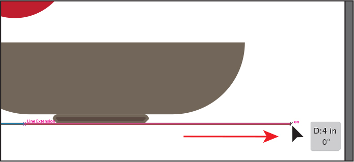
To change the length of the line from the center, move the pointer over one of the ends, press Option (macOS) or Alt (Windows), and drag away from the center. Drag until the line is 4 inches, and release the mouse button and then the key.
If you drag a line in the same trajectory as the original path, you will see the words “Line Extension” and “on” appear at opposite ends of the line. These appear because the Smart Guides are turned on.
Drag across the two shapes that make up the bowl and the line beneath. Click the Group button in the Properties panel to keep the artwork together.
Using Image Trace to convert raster images into editable vector art
In this part of the lesson, you’ll learn how to work with the Image Trace command, which converts a raster image, like a JPEG, into editable vector artwork. Tracing can help turn something you drew on paper—for instance, a raster logo, a pattern or texture, or hand-drawn type—into editable vector art. In this section, you’ll trace a picture of a lemon to get shapes.
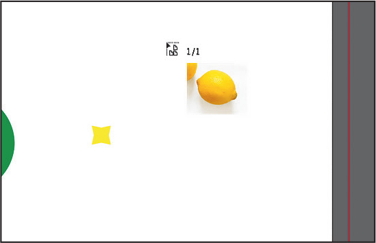
Choose File > Place. In the Place dialog box, select the lemon.jpg file in the Lessons > Lesson03 folder on your hard disk, leave all options at their defaults, and click Place.
Click in an empty part of the artboard to place the image. It won’t fit on the artboard, but that’s okay.
To center the selected image in the Document window (since it’s rather large), choose View > Zoom Out.
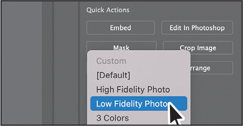
With the image selected, click the Image Trace button in the Properties panel to the right of the document, and choose Low Fidelity Photo from the menu.
 Note
NoteYou can also choose Object > Image Trace > Make, with raster content selected, or begin tracing from the Image Trace panel (Window > Image Trace).
This converts the image into an image tracing object. That means you can’t edit the vector content yet, but you can change the tracing settings or even edit the image you just placed in Photoshop and then see the updates if the image is linked to the Illustrator file.
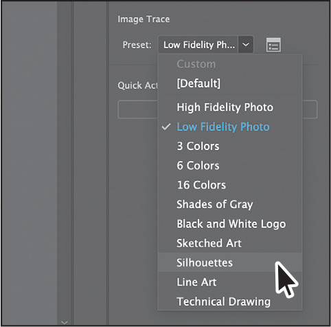
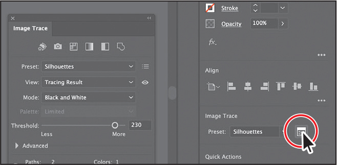
Choose Silhouettes from the Preset menu that’s showing in the Properties panel.
The Silhouettes preset will trace the image, forcing the resulting vector content to turn black. This is useful when you want to get the main shape from the tracing. An image tracing object is made up of the original source image and the tracing result, which is the vector artwork. By default, only the tracing result is visible. However, you can change the display of both the original image and the tracing result to best suit your needs in the View menu you will see in the Image Trace panel you open next.
 Tip
TipThe Image Trace panel can also be opened by choosing Window > Image Trace.
Click the Open The Image Trace Panel button (
 ) in the Properties panel.
The buttons along the top of the Image Trace panel are saved settings for converting the image to grayscale, black and white, and more. Below the buttons at the top of the Image Trace panel, you will see the Preset menu. This is the same menu as in the Properties panel. The Mode menu allows you to change the color mode of resulting artwork (color, grayscale, or black and white). The Palette menu is also useful for limiting the color palette or for assigning colors from a color group.
 Tip
TipYou can deselect Preview at the bottom of the Image Trace panel when modifying values so Illustrator won’t apply the trace settings to what you are tracing every time you make a change.
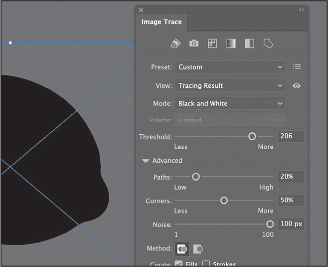
In the Image Trace panel, click the triangle to the left of the Advanced options to reveal them. Change the following options in the Image Trace panel, using these values as a starting point:
Threshold: 206 (Any pixels that are darker than the threshold value are converted to black.)
Paths: 20% (For path fitting. A higher value means a tighter fit.)
Corners: 50% (The default setting—a higher value means more corners.)
Noise: 100 px (Reduce noise by ignoring areas of a set pixel size. A higher value means less noise.)
Close the Image Trace panel.
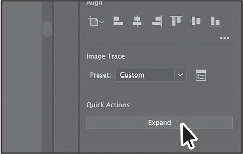
With the lemon tracing object still selected, click the Expand button in the Properties panel.
The lemon is no longer an image tracing object but is composed of shapes and paths that are grouped together.
Cleaning up traced artwork
Since the lemon image has been converted to shapes using the Image Trace command, you can now refine the shapes to make the lemon look better.
With the lemon artwork selected, click the Ungroup button in the Properties panel to break apart the different shapes and edit them separately.
Deselect the artwork by choosing Select > Deselect.
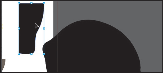
Click the extra shape that was traced. Use the figure as a guide. Press Delete or Backspace to remove it.
Click the lemon shape to select it. To change the color, click the Fill color box in the Properties panel. In the panel that opens, make sure that the Swatches option (
) is selected at the top. Select a yellow color to fill the lemon.To make the edges a little bit smoother, you’ll apply the Simplify command. The Simplify command reduces the number of anchor points that the path is made of without affecting the overall shape too much.
With the lemon selected, choose Object > Path > Simplify.
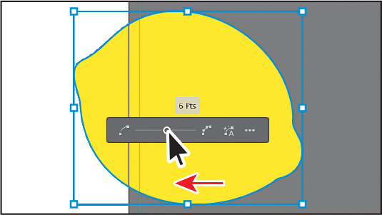
In the Simplify options that appear, by default the Reduce Anchor Point slider is set to an auto-simplified value. Drag the slider to the left to remove a few more points.
You can drag the slider to the left to reduce the anchor points and further simplify the path. The position and value of the slider specify how closely the simplified path matches the curves of the original path. The closer the slider is to the minimum value on the left, the fewer the anchor points there are, but the path will most likely start to look different. The closer the slider is to the maximum value on the right, the closer the precision of the original curve.
Click More Options (
) in the Simplify options to open a dialog box with more options.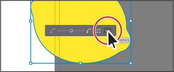
In the dialog box that opens, make sure Preview is selected to see the changes happen. You can see the original number of anchor points (Original) of the lemon and the number of anchor points after applying the Simplify command (New). Drag the Simplify Curve slider all the way to the right (Maximum). This is a great starting point and the artwork will look like it did before you applied the Simplify command.
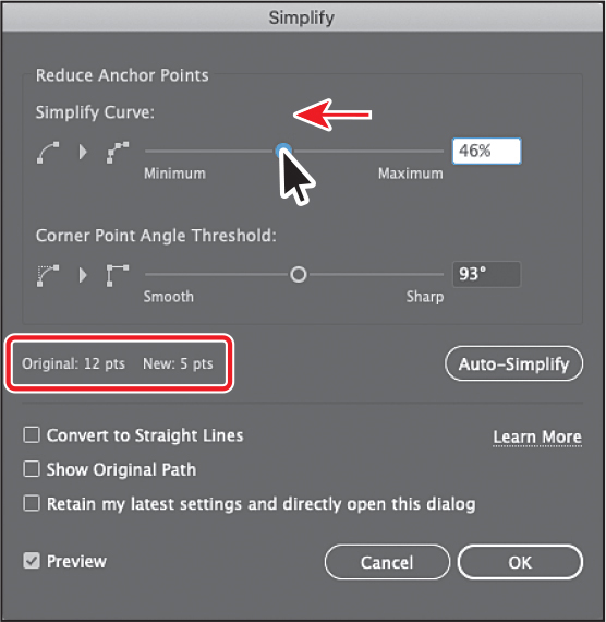
Drag the slider to the left until you see New: 5 pts (circled in the figure). You’ll need to drag a little and then release to see the New value change. Click OK.
NoteIf the Angle Threshold you see is different from the figure, that’s okay. You can change it to match the figure if you like.
For the Angle Threshold, if the angle of a corner point is less than the angle threshold, the corner point is not changed. This option helps keep corners sharp, even if the value for Curve Precision is low.
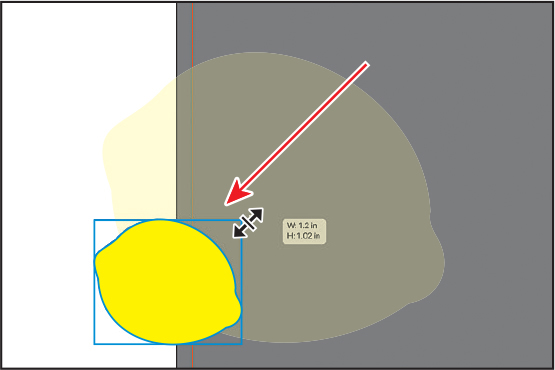
To scale the lemon, press the Shift key, and drag a corner to make it smaller. When you see a width of the approximately 1.2 inches in the tool tip, release the mouse button and then the key.
Drag the lemon into an empty area of the artboard.
Choose File > Save.
Working with drawing modes
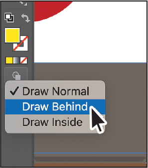
Illustrator has three different drawing modes available that are found at the bottom of the toolbar: Draw Normal, Draw Behind, and Draw Inside. Drawing modes allow you to draw shapes in different ways.
![]() Tip
Tip
You can cycle through the drawing modes by pressing Shift+D.
Draw Normal mode: You start every document by drawing shapes in Normal mode, which stacks shapes on top of each other.
Draw Behind mode: This mode allows you to draw behind all artwork on a selected layer if no artwork is selected. If artwork is selected, the new object is drawn directly beneath the selected object.
Draw Inside mode: This mode lets you draw objects or place images inside other objects, including live text, automatically creating a clipping mask of the selected object. You’ll learn more about masks in Lesson 15.
Placing artwork
Next you’ll place artwork from another Illustrator document that contains text shapes and artwork you will use to create another piece of fruit.
![]() Tip
Tip
The orange group is made of a circle drawn with the Ellipse tool, a star drawn with the Star tool, and a series of lines drawn with the Line Segment tool.
Choose File > Open. In the Open dialog box, select the artwork.ai file in the Lessons > Lesson03 folder on your hard disk, and click Open.
Select the Selection tool (
) in the toolbar. To select all of the content, choose Select > All On Active Artboard. Choose Edit > Copy.Click the Postcard.ai tab to return to the postcard document.
Choose View > Fit Artboard In Window.
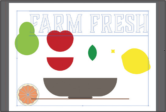
Choose Edit > Paste to paste the “FARM FRESH” text and part of the artwork for an orange.
Choose Select > Deselect.
Using Draw Inside mode
Now you’ll add the artwork of the orange you copied from the artwork.ai file to the inside of the red half-circle using the Draw Inside drawing mode. This can be useful if you want to hide (mask) part of the artwork.
Click the red half-circle copy you made earlier when creating the apple.
Click the Fill color box in the Properties panel on the right. In the panel that opens, make sure that the Swatches option (
) is selected at the top. Select an orange color to fill the shape. I chose the color with the tool tip “C=0 M=50 Y=100 K=0.”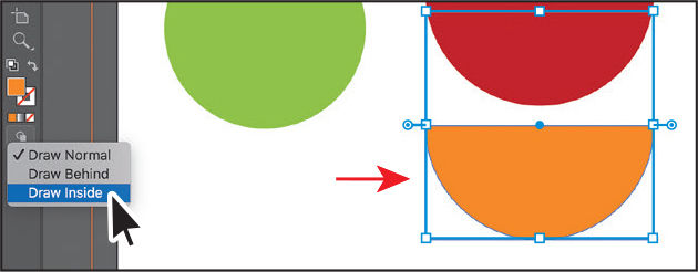 Note
NoteIf the toolbar you see is displayed as a double column, you will see all three of the drawing modes as buttons toward the bottom of the toolbar.
With the orange half-circle selected, choose Draw Inside from the Drawing Modes menu (
 ), near the bottom of the toolbar.
This button is active when a single object is selected (path, compound path, or text), and it allows you to draw within the selected object only. Notice that the orange shape has a dotted open rectangle around it, indicating that Draw Inside mode is still active. You can draw, place, or paste content into a shape with Draw Inside mode active. The shape you are about to add content inside of does not need to be selected.
Select the Selection tool (
), and click the artwork of the orange (the fruit) you pasted to select it. Choose Edit > Cut to cut the selected artwork from the artboard.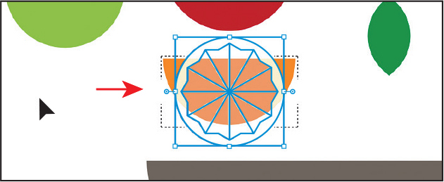
Choose Edit > Paste.
The artwork is pasted within the orange half circle since it was selected when entering Draw Inside mode.
TipYou can separate the artwork again by choosing Object > Clipping Mask > Release. This will make two objects, stacked one on another.
Click the Drawing Modes button (
 ) toward the bottom of the toolbar. Choose Draw Normal.
When you are finished adding content inside a shape, you can choose Draw Normal so that any new content you create will be drawn normally (stacked rather than drawn inside).

Choose Select > Deselect and then choose File > Save..
Editing content drawn inside
Next you’ll edit the orange artwork inside of the shape to see how you can later edit content inside.
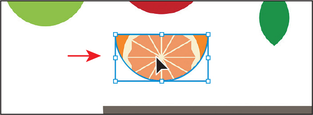
With the Selection tool (
) selected, click to select the orange artwork you pasted. Notice that it selects the half-circle shape instead.The half-circle shape is now a mask, also called a clipping path. The half-circle shape and the orange pasted artwork make a clip group and are treated as a single object. If you look at the top of the Properties panel, you will see Clip Group. As with other groups, if you would like to edit the clipping path (the object containing the content drawn inside it) or the content inside, you can double-click the Clip Group object.
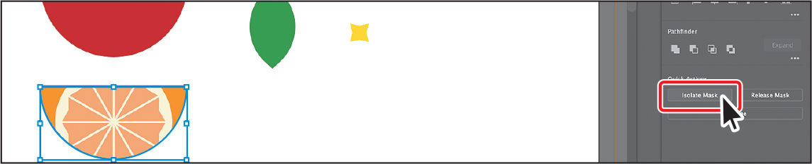
With the clip group selected, click the Isolate Mask button in the Properties panel to enter Isolation mode and be able to select the clipping path (half-circle shape) or the orange pasted artwork within.
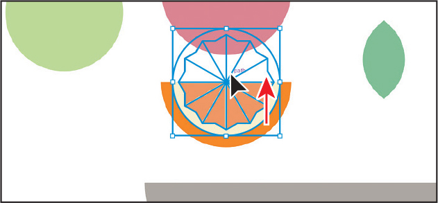
Click the orange pasted artwork within the map boundaries, and drag it to be more centered in the half-circle.
Press the Escape key to exit Isolation mode.
Choose Select > Deselect.
Working with Draw Behind mode
Throughout this lesson, you’ve been working in the default Draw Normal mode (without knowing it!). Next, you’ll draw a rectangle that will cover the artboard and go behind the rest of the content using Draw Behind mode.
![]() Note
Note
If the toolbar you see is displayed as a double column, you will see all three of the drawing modes as buttons toward the bottom of the toolbar.
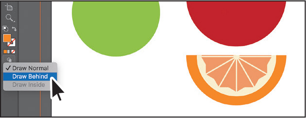
Click the Drawing Modes button (
 ) at the bottom of the toolbar, and choose Draw Behind.
As long as this drawing mode is selected, every shape you create using the different methods you’ve learned will be created behind the other shapes on the page. The Draw Behind mode also affects placed content (File > Place).
Press and hold on the Line Segment tool (
) in the toolbar, and select the Rectangle tool ().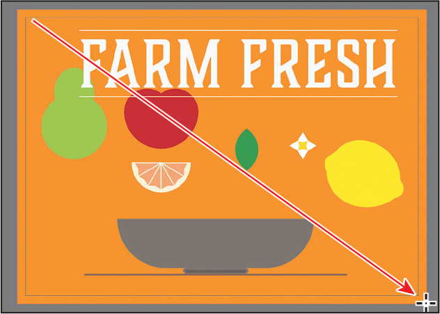
Move the pointer off the upper-left corner of the artboard where the red bleed guides meet. Press and drag to the lower-right corner of the red bleed guides.
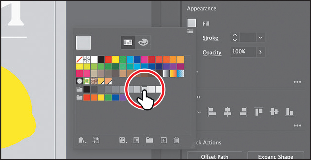
With the new rectangle selected, click the Fill color box in the Properties panel. Make sure that the Swatches option (
) is selected, and then change the fill color to a gray color with the tool tip “C=0 M=0 Y=0 K=20.”Press the Escape key to hide the panel.
Choose Object > Lock > Selection to lock the rectangle.
Click the Drawing Modes button (
) toward the bottom of the toolbar. Choose Draw Normal.
Finishing up
To finish the postcard, you’ll move the artwork into position on the artboard, rotate some, and make copies.
Choose View > Fit Artboard In Window to see the entire artboard, if necessary.
Select the Selection tool (
) and click one of the red shapes in the apple. Press the Shift key, click the remaining two shapes, and then release the key.Click the Group button in the Properties panel to group the apple shapes together.
Drag each piece of fruit and the text into position.


Make copies of the fruit and leaf artwork. To do so, click each piece of artwork, and choose Edit > Copy and then Edit > Paste.
To rotate a group, you can move the pointer just off a corner of the selected artwork and drag when you see the rotate arrows (
). Note
NoteIf you don’t see the Arrange button in the Properties panel, you can also choose Object > Arrange and choose an arrangement option.
To bring artwork in front of other artwork, click the artwork to select it. Click the Arrange button in the Properties panel, and choose Bring To Front.
Artwork that is behind other artwork was created first.
Choose File > Save.
To close all open files, choose File > Close a few times.
Review answers
1 You can set up a document for different kinds of output, such as print, web, video, and more, by choosing a category. For example, if you are designing a web page mockup, you can select the Web category and select a document preset (size). The document will be set with the units in pixels, the color mode as RGB, and the raster effects to Screen (72 ppi)—all optimal settings for a web design document.
2 There are five shape tools in the Essentials workspace: Rectangle, Ellipse, Polygon, Star, and Line Segment (the Rounded Rectangle and Flare tools are not in the toolbar in the Essentials workspace).
3 After you draw a rectangle, ellipse, or polygon (or rounded rectangle, which wasn’t covered) using a shape tool, you can continue to modify its properties, such as width, height, rounded corners, corner types, and radii (individually or collectively). This is what is known as a Live Shape. The shape properties, such as corner radius, are editable later in the Transform panel, in the Properties panel, or directly on the art.
4 Draw Inside mode lets you draw objects or place images inside other objects, including live text, automatically creating a clipping mask of the selected object.
5 You can convert a raster image into editable vector shapes by selecting it and then clicking the Image Trace button in the Properties panel. To convert the tracing to paths, click Expand in the Properties panel, or choose Object > Image Trace > Expand. Use this method if you want to work with the components of the traced artwork as individual objects. The resulting paths are grouped.