
Things you will learn in this chapter are as follows:
- Electricity
- Current
- Voltage
- Resistors
- Capacitors
- Series and parallel connections
- Sensors
- Physics behind sensors
- Common sensors to be used in the projects
- Making your own sensor
When was the last time you spotted lightning? Have you ever felt a jolt while getting out of your car, during winters? How do you think the lights go on immediately after you press the switch?
From static electricity to electric current to the lightning in the sky, these are all examples of various effects of electricity.
Electricity is a physical phenomenon that occurs due to the presence and flow of the electric charge (the unit by which charge is measured is coulomb). Electricity causes many effects that we come across everyday.
All electronic devices-be it our phones, headphones, watches and clocks-all operate on the exact same power source, that is movement of electrons. We know now that the movement of charge (or electrons) causes electricity.
Voltage is the charge difference between two points on a circuit (a circuit is a closed loop where the charge flows from one point to another, usually from a higher charge potential to a lower charge potential).
In similar terms, current is defined as the rate at which the charge follows. Resistance is the tendency of this material to resist the flow of charge. Therefore, whenever we talk about these terms, we are really just talking about the flow of electrons (charge).
We will learn about all of these principals in detail now.
Before we dig into the intricacies of voltage, let's first go through an exercise.
Note
Make a list of five gadgets around you. Under the supervision of an adult, collect the power chord or chargers of these gadgets. Find the sticker on it that shows various numbers. Can you spot it? Use someone's help to do so. Now make a table, and write down the names of the gadgets in one column and numbers that end in a V sign in the other column in your notebook.
What you did above was to write down the voltage rating of the gadgets around you. You will always use this information to identify and understand what the gadgets need to run safely. So, our question arises: what is voltage?
Voltage is the difference in amount of charge between two points in a circuit; this can also be defined as the amount of potential energy between two points on a circuit (or the potential difference between two points). One point has more charge (electrons) than the other. Voltage is scientifically represented by the symbol V, and the unit is volt, named after Alessandro Volta, the inventor of first chemical battery.
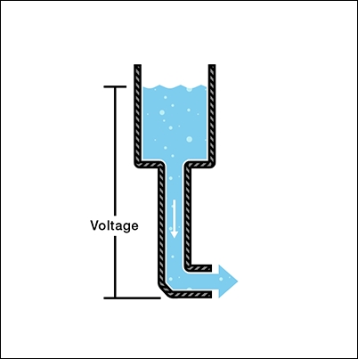
The best way to understand voltage, current, and resistance is through the water tank example.
Look at the water tank in the following image.
In this example, water represents charge, the pressure of water inside the tank represents voltage, and the flow of water represents current.
The water tank in this case is at a height above the ground. There is an opening or a hose at the bottom of the tank. When you open the hose, the pressure at the hose end can represent voltage. The amount of water in the tank is directly proportional to the pressure at the hose. The more the water, the more the pressure; similarly, the more the charge, the more the voltage.
As the amount of water in the tank decreases, the pressure and the rate of flow of water at the tap also decreases.
The same logic applies to batteries that hold charge: the more we use the charge of the batteries, the less the voltage becomes, and hence, the current flowing through it also decreases.
You might have faced this at home, in TV remotes, watches, or gaming consoles that run on batteries. This is significantly visible in flashlights, where the light from the bulb significantly decreases with the drop in voltage. Let's talk about current now.
Before we move on to understanding current, let's go back to the previous exercise and add something more to it.
What you marked now was the current ratings of the gadgets. Voltage and current ratings written on the devices are also known as power ratings. Simply put, power rating is the highest power inputs (read voltage and current) the appliance is safe to function in.
Let's understand more about current now.
Electrons flow from the negative terminal of the battery (more number of electrons) to the positive terminal terminal of the battery (less number of electrons), just like water flowing from a tank at a higher altitude to a tank at sea level or for a better analogy overhead tank in your house to water tap in your kitchen. Current is caused by the flow of charge (electrons), but conventionally, the direction of current is the opposite direction of the flow of electrons, i.e. positive to negative.
It is important to note that whenever you see a circuit, the flow of current will start from the positive terminal of the battery and end at the negative terminal of the battery.
In the preceding diagram, the amount of water flowing through the tap can be thought of as current. The more the pressure, the more the water flow; this implies that the more the voltage, the more the current.
With water, we would measure the volume of water flowing over a period of time; with charge however, we would calculate the charge flowing through the circuit for a period of time. Since charge is measured is coulombs, current (written as I) will be measured as coulombs per second or Ampere (Amp) after André-Marie Ampère.
Say we have two tanks of the same volume, but the hose in one tank is bigger than the other; water flowing through the one with the bigger hose will be more in quantity than the other. The size of the hose here restricts the amount of water that can flow out.
It should be noted that the water pressure at both the hoses will be the same since the capacity to store charge for both the tanks is the same when the water is not flowing. When the water starts flowing though, the narrower hose will show less flow of water than the wider one as shown in the following diagram:

In the current analogy, the current flowing through the narrower hose will be less than the wider one. If we want the current to be the same at both the hoses, we will have to increase the voltage in the tank with the narrower hose as shown in the following diagram:

When the pressure (voltage) increases at the end of the narrow hose, it pushes out more water (current). Through this example, we can see that there is a relationship between current and voltage. The voltage in a circuit is directly proportional to the current, but there is also a very important third factor: the size of the hose or resistance. We can now add another term here; the size of the hose is equivalent to the resistance. We will have a look at it in the following sub-section.
Has it ever happened that your parents asked you to clean your room, but you did not want to? You just wanted to sit and play games instead. That force inside you that doesn't want you to do something is called resistance. Speaking in terms of electronics, resistance is the very basic property of any material that does not want the charge to flow.
Let's consider two water tanks again, one with a wider hose and another with a narrower hose. From the following diagram, we can clearly see that the narrower pipe offers more resistance to the flow of water than the wider hose. We cannot fit as much volume of water in the narrower pipe as we can in the wider pipe, as shown in the following diagram:
In electrical analogy, we can state that the preceding example is of two circuits with the same voltage (pressure on hose) but different resistances (area of cross section of the hose). The circuit that has a higher resistance shows less amount of charge flow (current) through it. You can understand this better with the following diagram:

Resistance (represented as R) is measured in Ohm (Ω) after Georg Simon Ohm. Thus, 1 Ohm is the resistance between two points in a circuit when 1 volt of voltage applied across both the points results in 1 ampere of current flowing through the circuit. It is represented by Ω, which is called omega and pronounced Ohm.
The following is the image of what a resistor looks like:

Image source: http://p.globalsources.com/IMAGES/PDT/B1053091783/14W-to-5WS-Carbon-Film-Resistor.jpg
The following table explains the learnings from preceding water diagrams:
|
Voltage (Pressure) |
Current (Flow of water) |
Resistance (restriction) |
|
Increases |
Increases |
Same |
|
Same |
Decreases |
Increases |
|
Decreases |
Same |
Decreases |
To remember the relationship more easily, just fill in the blanks with the contents from the same row.
Voltage (pressure) ________ and current (flow of water)_______ when resistance (restriction) ____________.
Now we move on to another interesting component of electricity, the capacitor.
A capacitor is a two-terminal component that has the ability to store electrical energy; they can be compared to a fully charged electric battery. A capacitor only stores charge for a very small time in an electric field. A capacitor's capacity or capacitance (the ability of the component to store charge) is measured in Farad (F), named after Michael Faraday. Capacitance is defined as the ratio of electric charge (Q) on each conductor to the potential difference (V) between both.
You can think of a capacitor as a stretchable membrane (like a balloon or spandex) that is kept between the two ends of a water pipe. Please refer to the following diagram:

The pump in the system can be compared to a battery.
Initially, the membrane is not stretched, hence the membrane, by itself, has no force in it. As the water starts starts flowing from the pump, it pushes against the membrane and starts stretching it.
While the membrane is stretching, it will push the water on the other side to move a little making it look like water is flowing.
When the membrane reaches its maximum limit, it will exert a pressure equal to the pump’s pressure. At this point, the water flow will stop .
This is exactly how capacitors work in electric circuits as well.
The image below shows what a capacitor looks like:

Image source: http://hansenhobbies.com/products/eleccomps/cap_330uf_25v_alu_rad/img1_big.jpg