We all know what a switch is don't we. We just read about it in the previous chapter. We know how it works conceptually. Let's see how it works practically and in circuits.
In this project, we will use a push button switch. This is how it looks.

Image source: https://www.sparkfun.com/products/97
The working principle of the switch is rather simple. You press it, circuit connection is formed hence the circuit works, if you release it, the circuit breaks, so the circuit doesn't work.
At the stage when the pushbutton is un-pressed, we will call the state of pushbutton to be open. When the pushbutton is pressed, we will call that state as closed.
We will use the following components:
- Resistor - 10KOhm
- Push button switch
- Breadboard
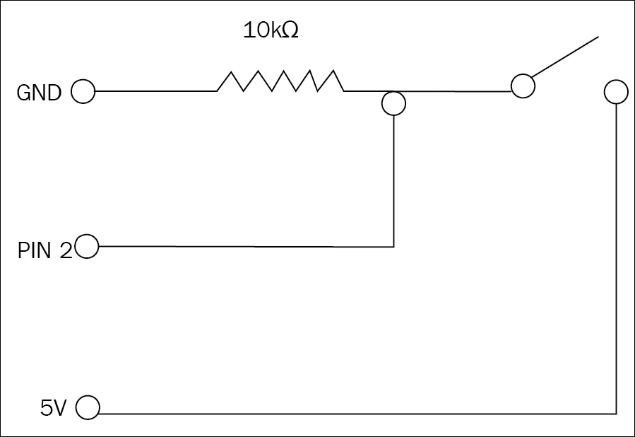
The following diagram explains how the circuit looks:
To make the above circuit connections, we are going to use a breadboard.
Note
Do you know what a breadboard is? Find out what a breadboard is how it works using the internet. You could use: https://learn.sparkfun.com/tutorials/how-to-use-a-breadboard to learn more about it. Return to this section once you have learned about the breadboard.
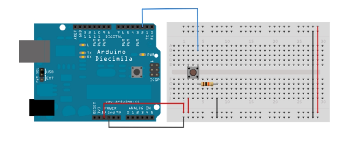
The above circuit shows the components in place. We will use the side rails on the extreme to run +5V in one line and GND on the other line.
We will proceed by connecting three wires to the board. The vertical rows will supply 5V and Ground. We will use Red wire and connect it to one of the vertical lines, this is the 5V line, black wire to the other vertical line. This will be our Ground line.
Digital pin 2 will be connected to one leg of the pushbutton using third wire, we will connect this to ground through a (10K Ohm) pull down resistor.
A pull down resistor brings any state which is not HIGH to LOW. More often than not, while working with switches, it was noticed that switches don't stay in the just open and closed state. There are times when the switch is released after pressing, but switch is neither completely open nor completely closed. This state is called a bouncing state. As the name suggest, switch is basically bouncing between states. So the pull down resistor is used to de-bounce the switch to a definite value of low.
The other leg of the button is connected to the 5 volts line. Let's look into details of what happens while the pushbutton is open or un-pressed. There is no connection between the two legs of the pushbutton, therefore the pin is connected to ground (remember we put the pull-down resistor?) and we read a LOW. Now, when the button is closed or pressed, it makes a connection between its two legs. This time, both the legs are connected to 5 volts, hence we read a HIGH.
If you disconnect the digital I/O pin from everything, the LED may blink erratically. This is because the input is floating - that is, it will randomly return either HIGH or LOW because the value is never absolute, it's like a balloon in a room that is neither touching the ceiling, not coming down to the ground. That's why you need a pull-up or pull-down resistor in the circuit.
Here is how the code looks like:

Code:
const int buttonPin = 2; //the number of the pushbutton pin
const int ledPin = 13; //the number of the LED pin

//variables will change:
int buttonState = 0; //variable for reading the pushbutton status

void setup() {
  // initialize the LED pin as output:
  pinMode(ledPin,OUTPUT);
  //initaliize the pushbutton pin as an input
  pinMode(buttonPin,INPUT);
}

void loop() {
  // read the state of the pushbutton value:
  buttonState = digitalRead(buttonPin);

  //check if the pushbutton is pressed
  //if it is, the buttonState is HIGH:
  if(buttonState == HIGH){
    //turn LED on:
    digitalWrite(ledPin,HIGH);
    }else{
      //turn LED off:
      digitalWrite(ledPin,LOW);
    }
  }
On the press of the button now, the LED should turn on and off otherwise. We will save this code for now and move on. Remember, every problem is like a jig saw puzzle. We know this part of the puzzle is in the right place. We don't have to necessarily re-use this code, we just have to understand the concept here. Let's work on the other parts now.
Till now, we have got our LED working, and with a little bit improvement on the code, we have our LED working on the push of a button. Let me rephrase that. An external influence (button) is triggering an action (LED on/off). Now let's think about what we wanted our external influence to be. We wanted a light sensitive bot right?
The only part of the puzzle that is left now is to create light sensitivity. Let's work on that now.