
Things you will learn about in this chapter are as follows:
- Microcontroller
- The process of coding a microcontroller
- Power supply
- Integrated Development Environment for Arduino
- Inside the working of a microcontroller
- Open-source software and hardware
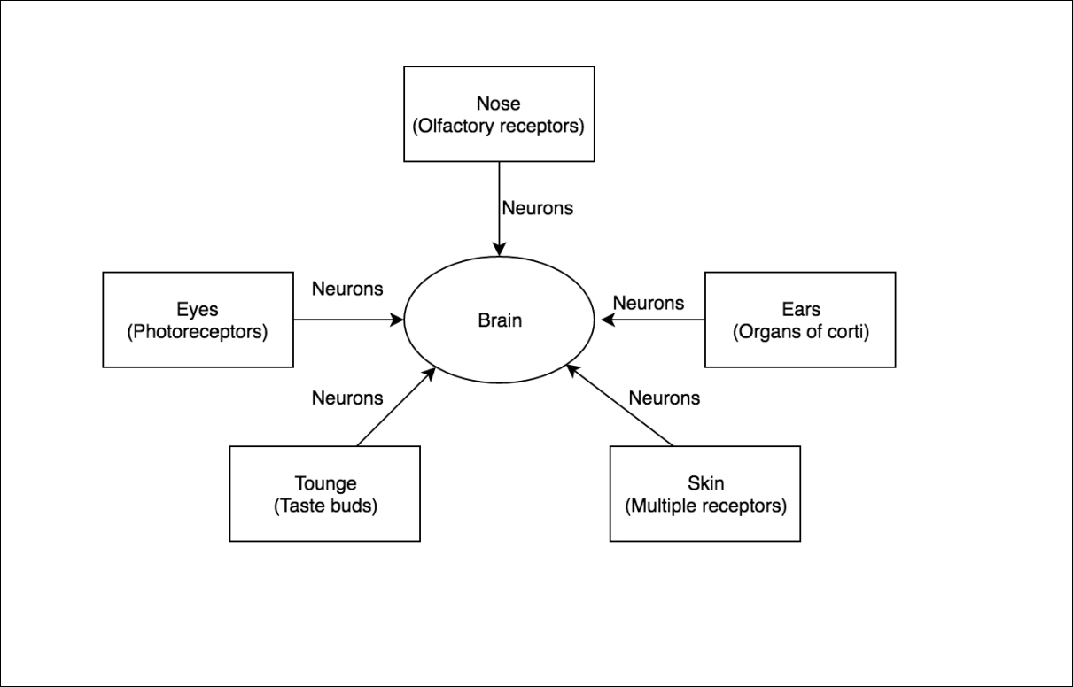
We will start exploring the microcontroller by comparing it to something we already know about: our brain. Let's refer to the following diagram. You have already seen this diagram in the last chapter, but this one has more clues to demystify the microcontroller:
Microcontrollers are a fascinating piece of technology created by our species. They consist of three major parts; they are:
- Processor core: This processes everything; it is is the brain of the microcontroller
- Program memory: This consists of instruction and acts as memory for the controller, just as our brain has memory.
- Inputs and Outputs: This is used to process external data. This is also where external devices connect all of which are controlled by the micro controller.
We will learn about these in detail. But before that, there is something you should know. A microcontroller is basically a miniaturization of our own brains! Let that sink in for a moment. Got goosebumps yet? Do you want to how our microcontrollers are inspired from the brain? Let's talk about it.
The brain of a microcontroller is its processor core. The bigger the processor core, the more efficiently it will function and execute the instructions given to it. A brain itself has various parts. Here is what we know about our brains.
Every morning when you get up and go to brush, take a bath, and get ready, have you ever wondered how you do most of these activities without really thinking about them? Do you learn to do these activities every day, or do you somehow just know how to do them? When you meet new people, you ask for their names, and soon after, you remember their names, don't you? You somehow know how to walk, how to talk, how to shake hands, how to read, right? Ever thought about how you just remember these things?
A part of our brain is responsible for storing information; we call it memory. Very similar to our brains, microcontrollers also have a tiny space where the code we write is stored.
Here is another question to you: ever thought about how you just wake up in the morning and fall asleep at night? Doesn't it feel like our bodies have a clock of its own? Somehow it knows what to do when. While we look at clocks and watches, our bodies have their own system.
This ability of our body to do things at certain points in time is sometimes loosely termed as our biological clock, too, and a part of our brain is dedicated to keeping track of everything we do, time-wise. Microcontrollers also need a system through which they can keep a check on everything they are working on. We call these clocks timers. You know, one of the many things I love about microcontrollers is that they are never late! One thing for you to remember here is that a micro controller is going to be late only if you make it.
You might have friends or family who are really good at Math and doing quick calculations. Did you know that the left part of our brain is responsible for that? We call this part the logical part of the brain. The right part of our brain controls all the creative things we do; painting, music, and a lot more creative activities are controlled by this part of our brain.
Microcontrollers, as we know by now, need to do a lot of calculations too. The section inside the microcontrollers that controls these activities is called the Arithmetic and Logic Unit or ALU.
The microcontrollers understand only binary that is 1s and 0s which is called the Digital format. So anything that we want out micro controller to understand needs to be broken down to 1s an 0s. It could be the color of the sky or temperature of water or just a simple multiplication. (I encourage you to learn how to convert out analog world to binary using the power of the internet. For example what is the binary(or digital format) of the number 20?) Our world however is Analog(we will learn more about it in the next few lines). When we work with sensors that read the physical world, we have to convert that into a format that our microcontroller understands.
For this, our microcontrollers are equipped with Analog to Digital Converters. We have Analog pins labeled A0 to A5 that can read the analog input voltage and convert that into a digital signal. Refer back to Chapter 3, Components and connections,voltage section. A micro-controller denotes 1 as a high voltage (usually 5V in Arduino) and 0 as low voltage (usually 0V in Arduino). The highest value ADC that can count at 5V is 1023; at 0V it is close to 0. So, if an input signal is of 2.9 volts, we use the ADC to find the value closest to either 0 volts or 5 volts for the system to understand.
The following diagram shows how I would do it:

In nature, when we work with signals in their natural form, this is exactly how they exist too, in a wavy form. It's not exactly the wave I made, but you get the idea, right?
The length and the style of these waves are very different from each other. When we want to read these values using a microcontroller, we will have to covert these waves in the format our micro controllers understand, which consists of 1s and 0s.
The following diagram shows how we can consider values low and high on ADC values:
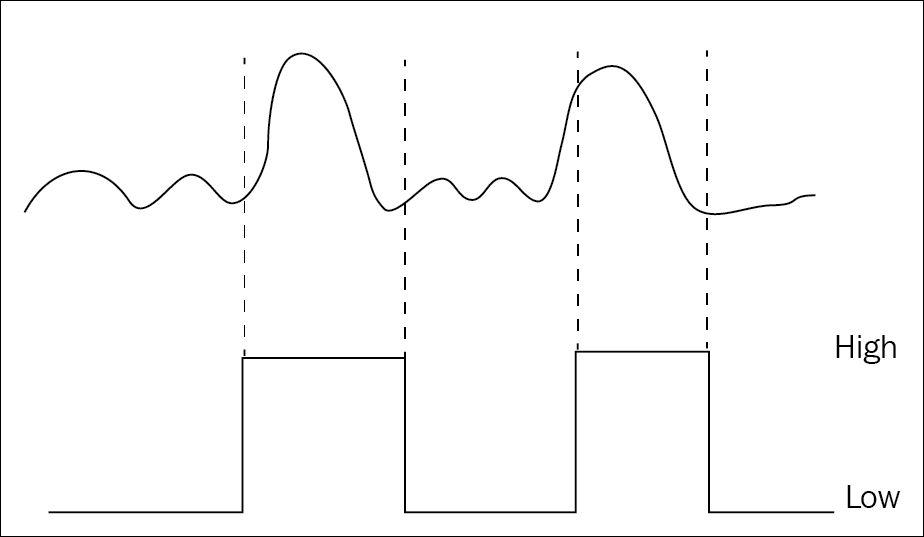
You will notice that anything in the preceding wave that is higher than the rest is considered high, and everything else is considered low.
The following image shows the Analog Pins on an Arduino Uno:
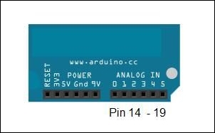
(http://cdn.instructables.com/FR2/B8NP/G0AMJ75C/FR2B8NPG0AMJ75C.MEDIUM.jpg)
Neurons in our brain carry input signals form the sense organs and output signals to respective part of the body. When I see my friends, I wave my hands to greet them. Neurons take signals from my eyes to the brain, and then the brain sends signals to my hands to wave. Similarly, microcontrollers have input and output lines to connect to sensors to read the inputs and various output lines to connect to the motors or anything else that we want to actuate.
You could also consider input lines as the entry gates to a mall and output lines as exit gates. More often than not, entry gates and exit gates are different from each other.
Registers are very similar in nature to memory. Registers in microcontrollers have very specific hardware-related functions in addition to memory. Hardware registers are used to act like an interface between software and peripherals. They can be imagined as tiny slots that can be used to give data to or take data from. Some registers are used for storing data temporarily, and they might not be physically connected to the pins, but other are physically connected to input/output pins, serial ports, and so on. Talking to these registers is how we perform operations such as running a motor or reading a value from a sensor.
There are three kinds of registers connected to every pin in Arduino: one register is for providing data direction, which means either input or output. You will see this being used at the pinMode() declaration in the code.
The second register is called the PORT register. When a pin has been set up as output, the PORT register is used. This is used when we use the digitalWrite() function.
The third register is called the PIN register. When a pin has been set up to read values, it uses the PIN register to read values. This is used during the digitalRead() function.
To break this down, all we need to remember is that Arduino has three different slots that interface the hardware (all input / output pins, memory, ALU, and so on) to the software being written in the micro controller.