
Now, it may have become apparent after explaining how ADC's work, that the Arduino can measure only an analog voltage. But our LDR changes its resistance depending on the amount of light falling on it. So how can we effectively change the voltage across the Arduino depending on the change of the resistance of the LDR?
We use a voltage divider!
A voltage divider is a very fundamental and simple circuit which basically divides a larger voltage into a smaller one depending on the values of the resistors in its circuit.
A voltage divider uses two resistors in series with an input voltage and can output an output voltage that is a fraction of the input.

A voltage divider
Image source: https://cdn.sparkfun.com/r/600-600/assets/4/0/3/a/e/511948ffce395f7f47000000.png
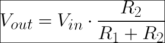
The output voltage depends on the resistances and the input voltage by the following equation:
Now, using this circuit, along with our LDR, we can manipulate the voltage input into our Arduino. All we have to do, is keep one of the two resistors of the voltage divider a constant, and the other resistor will be our LDR as shown in the following figure. Depending on the amount of light falling on the LDR, its resistance will change, and in turn, will vary the voltage flowing into the Arduino. This change in voltage will allow us to figure out whether there is light falling on the LDR or not.
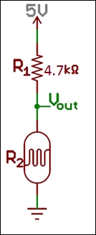
A voltage divider using a fixed resistor and a LDR
In this image, we have used a resistor of 4.5 kOhms because it is somewhere between the maximum and minimum resistance of the LDR. This is done so that we get a good variation in output voltages depending on the changing resistance of the LDR that follows the equation discussed earlier.
Now that we understand all there is to know to get our LDR to work, let's write a simple program to read voltage from an analog pin of our Arduino and output to the serial port.
Let's cut straight to the chase!
Start by hooking up our circuit as shown in the following screenshot, you will need a fixed 4.7k Ohm resistor along with your LDR and Arduino to get it to work.
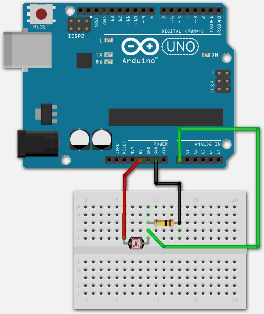
After connecting the sensor to the Arduino as shown, and uploading your sketch, start your Arduino IDE's Serial Monitor to see a stream of information.
int lightPin = A0;  //define a pin for Photo resistor

void setup()
{
    Serial.begin(9600);  //Begin serial communication
}

void loop()
{
   int level = analogRead(lightPin);
   Serial.println(level);  //Write the value of the photoresistor to the serial monitor.
   delay(10); //short delay
}
After connecting the sensor to the Arduino as shown, and uploading your sketch using the Arduino IDE, start your Arduino IDE's Serial Monitor to see a stream of information.
This is the stream of information from the sensor! Cover the LDR with your hands preventing light falling on it and see how the values change. Shine a torch and see how it affects the values.
Now let's walkthrough this code. The following line initializes a variable that represents the Arduino pin we have connected our LDR to. Notice the A in front of the number, this corresponds to the analog pins on the left side of the Arduino:
int lightPin = A0
In the following code lines, we initialized the serial communication required for the serial communication between the Arduino and the Arduino IDE's Serial Monitor:
void setup() {
 Serial.begin(9600);
}
In the following line, we initialized an integer called level that will hold the value of the reading on the analog pin:
int level = analogRead(lightPin);
The following line prints the value stored in level:
Serial.println(level);
This was just a glimpse! Have you heard of the phrase, there's always light at the end of the tunnel? We'll see just that, there is!