Chapter 3
A Lap around the CAD Track
IN THIS CHAPTER
![]() Setting up a simple drawing
Setting up a simple drawing
![]() Drawing some objects
Drawing some objects
![]() Zooming and panning in a drawing
Zooming and panning in a drawing
![]() Editing some objects
Editing some objects
![]() Plotting a drawing
Plotting a drawing
Chapters 1 and 2 introduce you to the AutoCAD world and to the AutoCAD interface. Other chapters in this book present the techniques that underlie good drafting practice. By now, you’re probably eager to start moving the cursor around and drawing something. This chapter leads you on a gentle tour of the most common CAD drafting functions, including setting up a new drawing, drawing and editing objects, zooming and panning the view, and plotting (or printing) a drawing. I don’t go into full detail about every option of every command, but I give you a feel for what it can do. Go ahead and slam the tires, and don’t worry about putting a dent in the doors!
In this chapter, you create a drawing of an architectural detail of a base plate and column. Even if you don’t work in architecture or building construction, this exercise gives you some simple shapes to work with and demonstrates commands you can use in most drafting disciplines.
Throughout this book, I show AutoCAD running in the Ribbon-based Drafting & Annotation workspace that is present in both AutoCAD and AutoCAD LT. Likewise, I tell you where to find commands and what to select by using the Ribbon.
Although the drafting example in this chapter is simple, the procedures that it demonstrates are real, honest-to-CAD-ness, proper drafting practices. I emphasize from the beginning the importance of proper drawing setup, putting objects on appropriate layers, and drawing and editing with due concern for precision. Some of the steps in this chapter may seem a bit strange at first, but they reflect the way that experienced AutoCAD users work. My goal is to help you develop good CAD habits and do things the right way from the start.
 The steps in this chapter, unlike the steps in most chapters in this book, form a sequence. You must complete the steps in order. Figuring out how to use AutoCAD is a little like figuring out how to drive, in which parallel parking comes before Indy car racing, except that with AutoCAD you’re free to stop in the middle of the street and take a break. If things get away from you, press Esc two or three times to terminate any command that’s in progress, and type the letter U and then press the Enter key to undo the last thing you did. Incidentally, U and UNDO are two similar commands and between them are probably the most-often-used commands in AutoCAD.
 If you find that selecting and editing objects work differently from the way I describe in this chapter, you have (or someone else has) probably changed the configuration settings on the Selection tab in the Options dialog box. Chapter 24 describes these settings and how to restore the AutoCAD defaults.
A Simple Setup
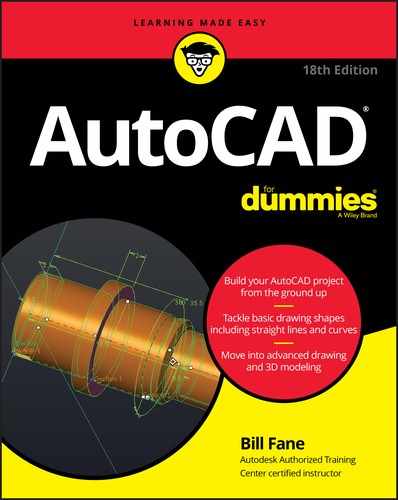
In this chapter, I walk you through the steps to create, edit, view, and plot a new drawing. See Figure 3-1 to get an idea of what the finished product looks like. I use Imperial units in this chapter (you know — inches and feet, for example). I describe how to set imperial units versus metric units in Chapter 4.
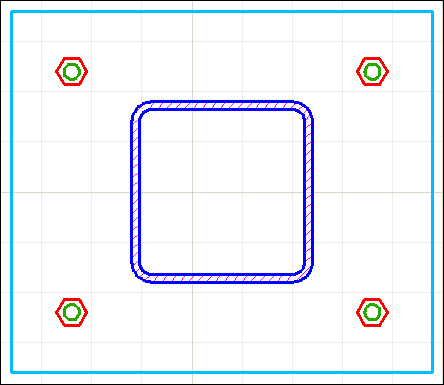
FIGURE 3-1: How base is my plate.
In the following exercise, you use several of the status bar buttons at the bottom of the screen. I don’t like the icons that AutoCAD displays, and I grew bored from hovering the mouse cursor over each button until the tooltip appeared. Earlier versions of AutoCAD allowed us to switch from icons to Text mode, wherein each button had a text label instead of an icon. Unfortunately, AutoCAD no longer supports this feature, so I have to refer to each button by its tooltip description along with the relevant icon in the margin. The good news is that you can toggle ten settings by using the F keys (such as F3), which I reference in the text in parentheses, as in (F3). A gray icon indicates that the button’s function is Off, while a light blue icon indicates On. (Your screen will show icons against a dark gray background, but I used a white background for a clearer image on the printed page.)
You can find the files I use in this sequence of steps at this book’s companion website: Go to www.dummies.com/go/autocadfd18 and download afd03.zip. The Zip file contains imperial and metric versions of the base plate exercise at various stages, and the Read Me file on the Downloads tab describes the files in details.
Pay attention to feedback from AutoCAD. Glance at the messages the program sends after each step via the command line at the bottom of the screen or the Dynamic Input tooltip near the cursor so that you become familiar with the names of commands and their options. If you don’t see messages next to the cursor as you use the program, click the Dynamic Input (F12) button on the status bar so that its icon is light blue rather than gray.
In this first set of steps, you create a new drawing from a template, change a few settings to establish a 1:10 scale (that is, 1 inch on the drawing is equivalent to 10 inches on the real object), and save the drawing:
-
Start AutoCAD.
As indicated in Chapter 1, the startup procedure can vary depending on your version of Windows and how it is set up.
- Start a new drawing that uses AutoCAD’s Imperial template.
-
Click the Templates bar at the bottom of the big Start Drawing icon.
 Don’t click the big Start Drawing icon itself or the New button on the Quick Access toolbar. You must use the down arrow. I explain why in Chapter 4 — humor me for now. Have I lied to you recently?
A list of drawing templates (DWT files) appears. Templates in AutoCAD are similar to templates in Microsoft Word and other programs. Chapter 4 describes how and why to create and use custom drawing templates.
-
Select
acad.dwt, as shown in Figure 3-2. (In AutoCAD LT, selectacadlt.dwt.)See Figure 3-2. AutoCAD creates a new, blank drawing that uses the settings in
acad.dwt. Theacad.dwttemplate (acadlt.dwtin AutoCAD LT) is AutoCAD’s default, plain-Jane (or should that be plain-Pat to be gender-neutral?) template for creating drawings that use imperial units (units expressed in inches or feet or both). Chapter 4 contains additional information about these and other templates.
-
-
Check your workspace.
 The workspaces in AutoCAD look similar. To make sure that you’re using the same workspace as I am in this chapter (and in most of this book), click the gear icon, near the right end of the status bar (and shown in the margin). If the check mark in the drop-down list isn’t beside Drafting & Annotation, click Drafting & Annotation.
 -
Set up the initial working environment.
Make the following settings:

 Click all the buttons on the left half of the status bar as necessary until they look gray, except Dynamic Input (F12) and Ortho (F8), which should be blue.)
-
 Turn the background grid (F7) on or off.
Most beginners seem to like it turned on, and most experienced users turn it off.
Some of the other settings can make point selection difficult. Start with them all turned off, and then toggle them on and off as needed. I tell you which ones to use in the remaining steps.
-
Set the drawing limits that define the working area.
-
Type LIMITS and press Enter.
(I explain drawing limits in more detail in Chapter 4.)
- For now, ignore the Dynamic Input tooltip next to the cursor, and look at the command line. AutoCAD echoes the command name and replies to it. Set the limits of the drawing area by responding to the prompts:
Specify lower left corner or [ON/OFF] <0.0000,0.0000>: Press EnterSpecify upper right corner <12.0000,9.0000>: 100,50
Don’t add a space before or after the comma of a coordinate value. It’s the final frontier. If you press the spacebar before you enter the entire coordinate value, AutoCAD will process only the text you've typed. -
-
Display the defined working area.
-
Start the Zoom command.
The Zoom command is hidden away in the Ribbon, so it is usually far faster and easier to simply type Z and press Enter.
ZOOM Specify corner of window, enter a scale factor (nX or nXP), or [All/Center/Dynamic/Extents/Previous/Scale/Window/Object] <real time>:… -
Type A and press Enter.
AutoCAD zooms so that the screen shows the limits (that is, All) of your drawing.
I use a special fontto show you what AutoCAD is saying. You either type the characters in bold and press Enter, or just press Enter (such as in Step 4a) to accept AutoCAD’s default option or recent value. For simplicity, rather than show AutoCAD’s complete response, I often show only what’s necessary for you to understand what’s going on. -
-
Establish the snap and grid drafting settings.
-
 Right-click the Display Drawing Grid button near the left end of the status bar and then choose Settings.
The Snap and Grid tab in the Drafting Settings dialog box appears, as shown in Figure 3-3. Note that AutoCAD LT lacks some options that are present in the full version of AutoCAD.
- Change the values in the Drafting Settings dialog box to match those in Figure 3-3, and click OK when you’re finished:
- Snap On: When selected, constrains the cursor to moving in an invisible grid of equally spaced points (0.5 units apart, in this case).
- Grid On: When selected, displays a visible grid of little dots or grid lines on the screen (5 units apart, in this case), which you can use as reference points. The grid doesn’t appear on printed drawings.
- Snap X Spacing: 0.5
- Snap Y Spacing: 0.5
- Grid X Spacing: 5
- Grid Y Spacing: 5
You see a network of grid lines, 0.5 units apart, with brighter lines every 5 units, in the drawing area. If you move the mouse pointer around and watch the coordinate display area at the left side of the status bar, you notice that the values still change in tiny increments, just as they did before. I have more information on snap mode and grid display in Chapter 4.
-
- Save your work:
-
Click the Save button on the Quick Access toolbar, or press Ctrl+S.
Because you haven’t saved the drawing yet, AutoCAD opens the Save Drawing As dialog box. Navigate to a suitable folder by choosing from the Save In drop-down list or double-clicking folders in the list of folders below it.
I remembered to remind you to remember where you save the file so that you can find it later. (And remember the three signs of old age: The first is loss of memory … I forget the other two.) -
Type a name in the File Name text box.
For example, type My Plate Is Base. Depending on your Windows Explorer or File Explorer settings, you may or may not see the
.dwgextension in the File Name text box. In any case, you don’t need to type it — AutoCAD adds it for you. -
Click Save.
AutoCAD saves the new DWG file to the folder you specified.
-
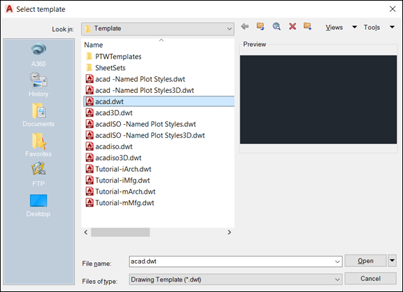
FIGURE 3-2: Starting a new drawing from a template.
FIGURE 3-3: Snap and Grid settings.
If you forget the name of the file later, simply click the Start tab in the upper-left corner of the drawing or check the Recent Documents list of the Application menu.
The good news is that it isn’t necessary to complete all these steps for every new drawing. Chapter 4 goes into more detail about drawing setup, describes why all these gyrations are necessary, and tells you how to avoid doing them more than once by defining your own template files.
Drawing a (Base) Plate
When your drawing is properly set up, you’re ready to draw some objects. In this example, you use the Line command to draw a steel base plate and column, the Circle command to draw an anchor bolt, and the POLygon command to draw a hexagonal nut.
AutoCAD, like most CAD programs, uses layers as an organizing principle for all objects you draw. Chapter 9 describes layers and other object properties in detail. For now, think of layers as sheets of transparent plastic lying on top of the drawing. You can hide or display individual drawing elements by simply removing or replacing their particular sheet of plastic.
In this example, you create separate layers for the base plate, column, anchor bolts, nuts, and crosshatching. This might seem like layer madness, but when you’re creating complex drawings, you need to use layers properly to keep everything organized.
The following steps demonstrate how to create and use layers, as well as how to draw lines, circles, rectangles, and polygons. You also see how to move, copy, mirror, offset, and apply fillets.
- Complete the drawing setup in the earlier section “A Simple Setup.”
-
Prepare to create the five layers you will use to organize the objects that will make up the base plate example by invoking the LAyer command.
Do one of the following:
-
 On the Layers panel of the Home tab, click the Layer Properties button.
The Layer Properties button is at the left edge of the Layers panel.
-
Enter LA from the keyboard.
As you type, a list of commands that start with LA appears near the cursor. The full command name is LAYER, but as soon as LA is highlighted, press Enter.
The LAyer command starts and AutoCAD displays the Layer Properties Manager palette, as shown in Figure 3-4. If you want to move any palette to a different screen location, just move the cursor to the vertical bar on the palette's left edge and then drag the palette to a new location.
-
- Follow these steps to create the needed layers:
-
Click the New Layer button.
It’s the leftmost of the group of four buttons that include the green check mark and the red X. AutoCAD adds a new layer to the list and gives it the default name Layer# where # is a number. For the first layer, the default name is Layer1 (see Figure 3-4).
-
Name That Layer.
Type Plate as the name of the first layer on which you’ll draw the base plate, and press Enter.
-
Click the color swatch or name (white) in the Color column of the new Plate row.
The Select Color dialog box appears, as shown in Figure 3-5.
-
Click the fourth color square (cyan/light blue, index color 4), for the first layer in the single, separate row to the left of the ByLayer and ByBlock buttons, and then click OK.
The Select Color dialog box closes, and the color for the Plate layer becomes cyan.
- With the Layer Properties Manager still open, repeat Steps 3a through 3d to create four more layers with these names and colors:
Layer Name
Color
Column
5 (blue)
Anchor Bolts
3 (green)
Nuts
1 (red)
Hatch
6 (magenta)
-
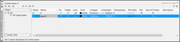
FIGURE 3-4: Creating a new layer.
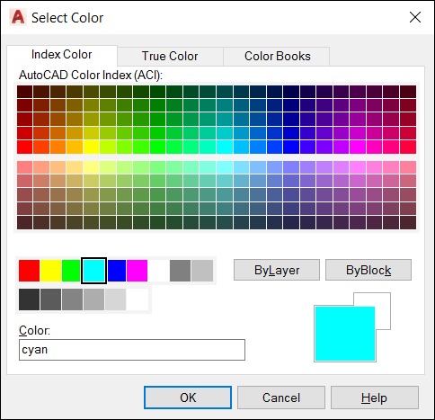
FIGURE 3-5: Select Cyan from the standard color tiles.
You don’t have to create a separate layer for every type of object you draw. For example, you can draw both the anchor bolts and nuts on a Hardware layer. Layer names and usage depend on industry and office practices, in addition to a certain amount of individual judgment. Having too many layers is better than having too few, because lumping together two or more layers is much easier than dividing the objects on one layer into two or more layers. I cover working with layers in more detail in Chapter 9.
Start with the objects that will be drawn on the Plate layer by following these steps:
- Make the Plate layer current before drawing the objects that make up the plate.
-
Double-click the Plate layer name.
A green check mark appears beside the layer name, indicating that it’s current. Anything you draw now will be on the Plate layer and will inherit its color.
-
Click the Close button (the X at the upper-left corner of the palette shown in Figure 3-4) to close the Layer Properties Manager palette.
The Layer Properties Manager palette can be left open on the screen or reduced to a vertical bar, but you might as well close it because you won’t need it again in this drawing session.
-
- Draw the base plate.
- Start the Line command by clicking its button on the Draw panel of the Ribbon’s Home tab or by typing L and pressing Enter.
- Draw three lines by responding to AutoCAD’s prompts:
LINESpecify first point: 68,7 and press Enter.Specify next point or [Undo]: Move the cursor to the left and then enter 36 You don’t need to enter a negative value for the second point. AutoCAD knows which way to draw the line because the cursor is located to the left of the first point. Because the Ortho (F8) button is turned on, AutoCAD constrains the cursor to move only exactly horizontally or vertically. In this case, a horizontal line exactly 36 units long is drawn, no matter how far away the cursor is from the first point. Specify next point or [Undo]: Move the cursor up and then enter 36Specify next point or [Undo]: Move the cursor to the right and then enter 36Specify next point or [Undo]: CEntering C (uppercase or lowercase) closes the line back to the starting point.
If you didn’t complete the previous steps, start from this point by using drawing afd03a-i.dwg, available in the afd03.zip download at www.dummies.com/go/autocadfd18. Download it to a suitable location, click the Application button, and then click Open. Browse to the file.
Time to add a bolt. You first need to change to the Anchor Bolts layer, and then draw the bolt:
- Go to the Layers panel of the Home tab.
-
Click the arrow at the right-hand end of the Layer drop-down list.
The current entry (from the running example) is Plate.
-
Choose the Anchor Bolts entry to set the Anchor Bolts layer as the current layer.
Using the Layer drop-down list, in the upper-right corner of the Layers panel of the Home tab of the Ribbon, saves you from having to open the Layer Properties Manager, select the layer, click the Set Current button, and close the Layer Properties Manager when you want to change to a different layer. Becoming an AutoCAD master is all about efficiency. The real heart of all human progress is laziness — we will work hard at finding ways to avoid work. - Draw the bolt:
- Start the Circle command, either from the Draw panel or by simply typing C and pressing Enter.
- Draw a circle by responding to AutoCAD’s prompts this way:
CIRCLESpecify center point for circle or [3P/2P/Ttr (tan tan radius)]: intOf: Move the cursor until it is close to the lower-left corner of the rectangle and then click when a green X appears at the intersection of the two lines.Specify radius of circle or [Diameter]:AutoCAD defaults to the radius of a circle, but you want to specify the diameter, so enter D.Specify diameter of circle: 1.5
-
Save your drawing.
AutoCAD automatically backs up your work, but you could still lose the last ten minutes or so. Now is a good time to press Ctrl+S.
Now add a hexagon nut for the bolt:
- Make the Nuts layer current by using the Layer drop-down list from the Layers Ribbon panel.
-
Start the POLygon command.
Its button is either in the upper-right corner of the Draw panel or on the drop-down list with the RECtangle button, depending on which command you last used. You can also type POL and press Enter.
- Draw a hexagon.
- Respond to these AutoCAD prompts:
POLYGON Enter number of sides <4>: 6Specify center of polygon or [Edge]: cenOf: Click anywhere on the circle.Enter an option [Inscribed in circle/Circumscribed about circle] <I>: C The Inscribed option draws a polygon whose corners touch the circumference of the imaginary circle. The Circumscribed option draws a polygon whose sides are tangent to the circumference of the circle and has nothing to do with a medical procedure. Bolt heads and nuts are normally specified by the width across the flats (unless you own a vintage British car such as a 1937 Rolls-Royce, where Whitworth wrenches are arbitrarily defined by the diameter of the thread), so choose the C option. -
Move the cursor.
The hexagon rotates about its center. You should still have ORTHO turned on, so AutoCAD shows only two possible choices for the vertex of the polygon: horizontal or vertical from the center of the imaginary circle.
- Move the mouse until a vertex is horizontal from the center of the circle.
- Respond to this AutoCAD prompt:
Specify radius of circle: 1.5 - Press Enter, and AutoCAD draws the hexagon.
- Respond to these AutoCAD prompts:
Okay, suppose that you draw the circle and the hexagon in the wrong location. Easy enough. Just move objects to another location as follows:
-
Start the Move command, which is on the Modify panel.
When AutoCAD prompts you, respond this way:
MOVESelect objects: Click the circle or the hexagon. 1 foundSelect objects: Click the hexagon or the circle. 1 found, 2 totalSelect objects: Press Enter.Specify base point or [Displacement]: 6,6Specify second point or <use first point as displacement>: Press Enter.Like magic, AutoCAD moves the hexagon and the circle six units to the right and six units up.
-
Take a break.
Press Ctrl+S to save the drawing. It may be time for a hydraulic break; remember that the mind can’t hold more than the bladder.
There are several different ways to produce additional nuts and bolts. The next two procedures combine to demonstrate one method:
- Start the COpy command, which is on the Modify panel. Then follow these prompts.
COPYSelect objects: p Selects the Previous selection set, being the objects you selected to move. 2 foundSelect objects: Press EnterCurrent settings: Copy mode = MultipleSpecify base point or [Displacement/mOde] <Displacement>: 0,24Specify second point or [Array] <use first point as displacement>: Press Enter.Presto! AutoCAD creates a copy of the circle and the hexagon 24 units above the first set.
- Start the MIrror command, found on the Modify panel. Then follow the prompts.
MIRRORSelect objects: p Selects the Previous selection set, being the first nut and bolt. 2 foundSelect objects: Click the upper circle or the upper hexagon. 1 foundSelect objects: Click the upper hexagon or the upper circle. 1 found, 4 totalSelect objects: Press Enter.Specify first point of mirror line: midof: Select the upper horizontal line.Specify second point of mirror line: Make sure Ortho (F8) is still on and pick a point above or below the upper line.Erase source objects? [Yes/No] <N>: Press Enter.That was a little faster than drawing four circles and four hexagons by hand, wasn’t it?
-
Draw the column. Start by selecting Column to set it as the current layer.
-
On the Layers panel of the Home tab, click the Layer drop-down list to display the list of layers. Select Column to set it as the current layer.
Now you’re ready to create the hollow column, starting with its outside profile. Be sure to keep the cursor in the drawing area during this step and the next one.
- Start the RECtang command, found on the Draw panel.
RECTANGSpecify first corner point or [Chamfer/Elevation/Fillet/Thickness/Width]: 44,16Specify other corner point or [Area/Dimensions/Rotation]: @12,18A rectangle is drawn in the middle of the square base plate.
-
Start the FILlet command, on the Modify panel, and watch the command line closely.
In this step, you round the corners of the column with the FILlet command and then use OFFset to give it a wall thickness.
FILLETCurrent settings: Mode = TRIM, Radius = 0.0000Select first object or [Undo/Polyline/Radius/Trim/Multiple]: rSpecify fillet radius <0.0000>: 2Select first object or [Undo/Polyline/Radius/Trim/Multiple]: pSelect 2D polyline or [Radius]: Move your cursor over the new rectangle and observe how AutoCAD shows you a preview. Click the rectangle.4 lines were filletedYou can pick the lines at each corner that need to be filleted (that’s eight picks), but because the column is a continuous polyline, a more efficient method in this case is to use the FILlet command’s Polyline option to fillet all four corners in one fell swoop. I discuss polylines in Chapter 6 and fillets in Chapter 11.
- Now give the column a ¾-inch wall thickness. Start the OFFset command. Once again, it’s a Modify item.
OFFSETCurrent settings: Erase source=No Layer=Source OFFSETGAPTYPE=0Specify offset distance or [Through/Erase/Layer] <Through>: .75Select object to offset or [Exit/Undo] <Exit>: Click the filleted rectangle. Make sure that the Object Snap (F3) status bar button is toggled off for these next prompts, or AutoCAD may offset the object back on top of itself:Specify point on side to offset or [Exit/Multiple/Undo] <Exit>: Move your cursor over the new rectangle and observe how AutoCAD shows you a preview. Click inside the rectangle.Select object to offset or [Exit/Undo] <Exit>: Press Enter.
There you go! You created a hollow structural shape with wall thickness and radiused corners (see Figure 3-6) in just four simple steps.
-
-
Press Ctrl+S to save the drawing.
AutoCAD saves the drawing and renames the previously saved version
drawingname.bak— for example,My Plate is Base.bak. AutoCAD uses the filename extension.bakfor a backup file. When (not if) things get out of hand, you can always rename the.bakfile to.dwgto return to the most recent version.
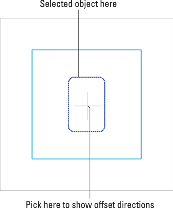
FIGURE 3-6: Give the column some thickness with OFFSET.
Now that you’ve given Dynamic Input a test drive, turn it off for the rest of this chapter by clicking its button on the status bar so that the button looks dimmed or by pressing F12. If you like using Dynamic Input, toggle it back on.
The drawing afd03b-i.dwg contained in the afd03.zip download includes the base plate and column and one anchor bolt.
Taking a Closer Look with Zoom and Pan
The drawing example in this chapter is uncluttered and manageable, but most real CAD drawings are neither — technical drawings are usually jam-packed with lines, text, and dimensions. CAD drawings are often plotted on sheets of paper that measure 2 to 3 feet on a side (in the hundreds of millimeters, if you’re a metric maven). Anyone who owns a monitor of that size probably can afford to hire a room full of drafters and therefore isn’t reading this book. You need to zoom and pan in drawings — a lot. I cover zooming and panning in detail in Chapter 5. These quick definitions should suffice for now:
- Zoom: Change the magnification of the display. When you zoom in, you move closer to the drawing objects so that you can see more detail; when you zoom out, you move farther away so that you can see more of the drawing area. Zooming does not change the size of the objects in the file. You can think of zoom in AutoCAD like the zoom function on your camera: You get closer, but you see less.
- Pan: Move from one area to another without changing the magnification. If you’ve used scroll bars in an application, you’ve panned the display. Panning does not change the location of objects in the file.
Frequently, zooming and panning let you see details better, and draw more confidently because you can see what you’re doing, and edit more quickly because object selection is easier when a bazillion objects aren’t on the screen.
Fortunately, zooming and panning in AutoCAD are as simple as they are necessary.
If you have a wheel mouse, you can zoom by simply rolling the wheel back and forth. To pan, press and hold the wheel (yes, the wheel is also a button) and drag the view around. These actions can be performed even when another command is active. If you don’t have a wheel mouse, run out and buy one. The small amount you’ll pay ($20 for cordless or $5 for a USB corded version) is easily recovered by your new operating efficiency. (Disclaimer: I have no financial interest in any mouse company or wheel company.)
Meanwhile, until you buy a wheel mouse, check out Chapter 5 to see how to use AutoCAD’s Zoom and Pan Realtime features.
The fastest way to return to a full view of the entire drawing is to type, at the command line Z A, which is short for Zoom All. Note the space between the two letters, and remember to press Enter or the spacebar after you type each letter.
Modifying to Make It Merrier
When you have a better view of the base plate by zooming, which I talk about in the preceding section, you can edit the objects on it more easily. In the following few sections, you use the Hatch command to add crosshatching to the column and use the Stretch command to change the shape of the plate. As always, I cover these commands in detail later in this book.
The drawing afd03c-i.dwg contained in the afd03.zip download adds the remaining anchor bolts.
Crossing your hatches
The next editing task is to add crosshatching to the space between the inner and outer edges of the column. The hatch lines indicate that the drawing shows a cross section of the column. To do so, follow these steps:
 Turn off Object Snap (F3), Ortho (F8), and Snap (F9) modes by clicking their respective buttons on the status bar or by pressing the indicated function key until the icons look dimmed.
- Select the Hatch layer from the Layer drop-down list at the top of the Layers panel on the Home tab.
-
 On the Home tab’s Draw panel, click the Hatch button (shown in the margin) or type Hatch at the keyboard.
The Hatch Creation tab appears on the Ribbon. For more information on this tab, and on hatching in general, see Chapter 15. Note that the Ribbon now has a light blue line around it and all the panels now show actions related to creating and formatting crosshatching.
-
On the Hatch Creation tab’s Pattern panel, select ANSI31.
Depending on your screen resolution, the panels may show more or less information. If you don’t see an ANSI31 sample swatch, click the down arrow at the bottom of the lower-right corner of the Pattern panel. A scrollable list of all available patterns will appear.
The ANSI31 swatch is the American National Standards Institute (ANSI) standard pattern number 31 (ANSI 31) and not ANS 131. -
Move the cursor over the drawing objects.
A live preview shows you the result if you click at the current crosshair position. AutoCAD prompts you:
Pick internal point or [Select objects/Undo/seTtings]: Move the cursor so it's between the inside and outside edges of the column. Zoom in if you need to get closer.The live preview shows the ANSI31 hatch pattern filling the space between the two filleted rectangles. Live preview not only shows you the pattern but also lets you preview the hatch angle and scale. In this case, it looks like the hatch pattern may be too fine.
- In the Scale window in the lower-right corner of the Hatch Creation tab’s Properties panel, change the value to 5 and press Tab to confirm it.
- Move the cursor back to the area between the two filleted rectangles to preview the hatch again. If it looks okay, click within the hatched area to confirm the hatch object, and then press Enter to finish the command.
The finished column and base plate should look much like the one shown in Figure 3-7.
-
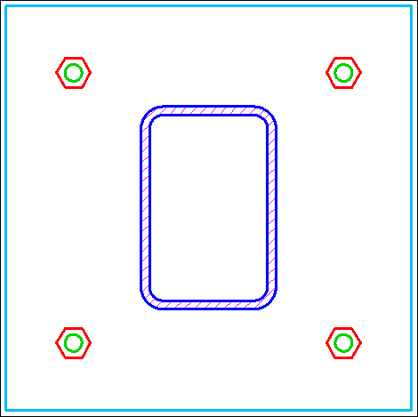
FIGURE 3-7: Button-downed base plate.
Perfect! But suppose that the nutty engineer (hey, I resemble that remark!) has decided that the column needs to measure 18 x 18 inches rather than 12 x 18 inches. Therefore, the base plate is too small, and the anchor bolts are in the wrong place. If you were drafting from paper on the drawing board, you’d pull out the eraser right about now to rub out half your effort — and if you were lucky, you’d have an electric eraser. At some point, you simply tore up the paper and started over, or labeled the appropriate dimensions as NTS (Not To Scale). It’s AutoCAD to the rescue.
Now that’s a stretch
The Stretch command is powerful: It can stretch or move objects, or stretch some and move others at the same time, depending on how you select them. The key to using Stretch is specifying a crossing selection box properly. Chapter 10 gives you more details about crossing selection boxes and how to use them with the Stretch and other editing commands.
Begin with the drawing from the previous section open in AutoCAD, or open the file afd03c-i.dwg contained in the afd03.zip download.
-
 On the Modify panel of the Home tab click the Stretch button (shown in the margin).
The Stretch command starts, and AutoCAD prompts you to select objects. This is one of those times and one of those command that requires you to watch the command line.
- Follow the command line instructions to click points from right to left to define a crossing selection box.
Select objects to stretch by crossing-window or crossing-polygon…Select objects: Click a point above and to the right of the upper-right corner of the plate (Point 1 in Figure 3-8).Specify opposite corner: Move the cursor down and to the left. Click a point below the plate, roughly under the center of the column (Point 2 in Figure 3-8).The pointer changes to a dashed rectangle enclosing a rectangular green area, which indicates that you’re specifying a crossing selection box. The crossing selection box must cut through the plate and column for the Stretch command to work (see Figure 3-8). You see the following:
11 foundSelect objects: Press Enter. - If these drafting settings aren’t already set this way, turn off Snap (F9) and turn on Ortho (F8) and Object Snap (F3). Then set a base point for the stretch operation.
Specify base point or [Displacement] <Displacement>: Move the mouse pointer over the lower-right corner of the plate, and click when you see a square box with an Endpoint tooltip.This point serves as the base point for the stretch operation. (Chapter 11 describes base points and displacements in greater detail.) As before, if you can’t get the cursor to snap to the endpoint, right-click the Object Snap (F3) button and select Endpoint.
-
Specify a displacement for the stretch operation.
AutoCAD prompts you at the command line:
Specify second point or <use first point as displacement>:Move the cursor horizontally to the right, type 6, and press Enter, as shown in Figure 3-9.
AutoCAD stretches the plate and column with its hatching, and moves the anchor bolts by the distance you indicated (see Figure 3-9).
-
Enter Z A at the command line to see the entire drawing.
If the first stretch didn’t work properly, press Ctrl+Z to undo, and then try again. Stretch is an immensely useful command that makes you wonder how drafters used to work with only erasers and pencils. - When the stretched drawing is as you want it, press Ctrl+S to save the drawing.
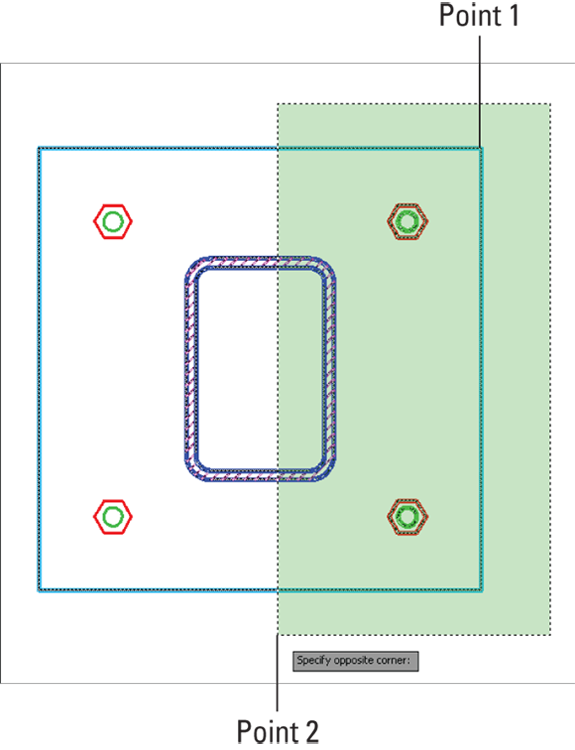
FIGURE 3-8: Specifying a crossing selection box for the Stretch command.
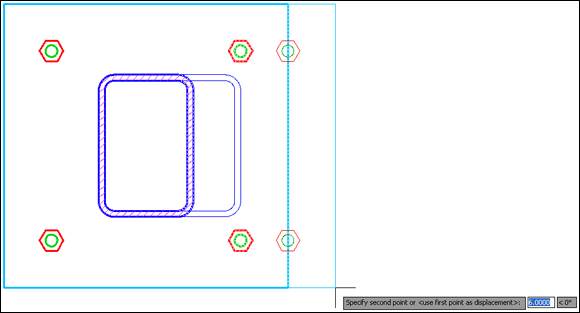
FIGURE 3-9: Stretching the base plate.
The drawing afd03d-i.dwg contained in the afd03.zip download is the stretched version of the base plate. How does it compare with your version?
After some drawing and editing, you may wonder how you’re supposed to know when to turn off or on the various status bar modes (Snap, Grid, Ortho, Object Snap, and others). Rest assured that you eventually begin to develop an instinctive sense of when they’re useful and when they’re in the way. If a mode is in your way or you realize that you need one, you can click the buttons or press the F keys at any time while using the editing and drawing commands. Later in this book, I give you more-specific guidelines.
Following the Plot
Looking at drawings on a computer screen and exchanging them with others via email or websites is all well and good, but sooner or later, someone — maybe you — will want to see the printed versions. Plotting drawings in AutoCAD (as CAD geeks refer to printing in AutoCAD) is a little more complicated, however, than printing a word processing document or a spreadsheet. You have to address issues such as drawing scales, lineweights, title blocks, and weird paper sizes. I delve deeper into plotting in Chapter 16, but this section describes an abbreviated procedure that can help you generate a recognizable printed drawing.
The steps in the following section show you how to plot the model space portion of the drawing. As Chapter 12 describes, AutoCAD includes a sophisticated feature — paper space layouts — for creating arrangements, usually including a title block, of the drawings you plot. Because I promised you a gentle tour of AutoCAD drafting functions, I save the discussion of paper space layouts and title blocks for later in this chapter. When you’re ready for the whole plotting enchilada, turn to Chapter 12 for information about how to set up paper space layouts and see Chapter 16 for full plotting instructions.
Plotting the drawing
The following steps should produce a satisfactory plot in almost all circumstances, though specific brands and models of plotter or printer might sometimes vary the result. Writers call this introduction the CYA, or Cover Your Backside, statement.
Follow these steps to plot a drawing:
-
 Click the Plot button on the Quick Access toolbar or press Ctrl+P.
The Quick Access toolbar is at the left end of the program’s title bar, just to the right of the Application button. The Plot icon looks like an ordinary desktop printer.
AutoCAD opens the Plot – Model dialog box, with the title bar showing what you’re plotting (Model, in this case). See Figure 3-10.
If you don’t see all the option windows shown down the right side of the dialog box in Figure 3-10, click the arrow in the lower-right corner.
-
In the Printer/Plotter section, select a printer from the Name drop-down list.
If in doubt, the Default Windows System Printer usually works.
-
In the Paper Size section, use the drop-down list to select a paper size that’s loaded in the printer or plotter.
Anything Letter size (8½ x 11 inches) [A4 (210 x 297mm)] or larger works for this example.
-
In the Plot Area section, select Limits from the What to Plot drop-down list.
This is the entire drawing area, which you specified when you set up the drawing in the section “A Simple Setup,” earlier in this chapter.
-
In the Plot Offset section, select the Center the Plot check box.
Alternatively, you can specify offsets of 0 or other amounts to position the plot at a specific location on the paper.
-
In the Plot Scale section, deselect the Fit to Paper check box and choose 1:10 from the Scale drop-down list.
You receive no prize for guessing the metric equivalent of 1:10.
-
In the Plot Style Table (Pen Assignments) section, click the drop-down list and choose
monochrome.ctb.The
monochrome.ctbplot style table ensures that all lines appear in solid black rather than as different colors or weird shades of gray. See Chapter 16 for information about plot style tables and monochrome and color plotting. -
Click Yes when the question dialog box appears, asking Assign This Plot Style Table to All Layouts?
You can leave the remaining settings at their default values as shown in Figure 3-10.
-
Click the Preview button.
If the plot scale you entered in the Plot dialog box is out of sync with the drawing’s annotation scale, the Plot Scale Confirm dialog box appears, advising you that the annotation scale isn’t equal to the plot scale. This drawing doesn’t contain text or dimensions, and you didn’t make the hatch annotative, so you can click Continue to generate the plot.
 Annotative scaling controls the printed size of text, dimensions, hatching, and other types of annotation objects at plot time — as long as the drawing’s annotation scale matches the plot scale. I explain annotative objects in Chapters 13 and 14.
The Plot dialog box disappears temporarily, and AutoCAD shows how the plot will look on paper
- Right-click in the preview area and choose Exit.
- If the preview doesn’t look the way you want, adjust the settings in the Plot dialog box and click the Preview button again. Continue to adjust the settings until the plot looks right.
-
Click OK.
The Plot Scale Confirm dialog box pops up again. You may be tempted to click Always Continue Under These Conditions, but I recommend against it until you’re more familiar with annotative objects.
The Plot dialog box closes. AutoCAD generates the plot and sends it to the printer. AutoCAD then displays a Plot and Publish Job Complete balloon notification from the right end of the status bar. A link labeled Click to View Plot and Publish Details displays more information about the plot job.
-
Click the Close (X) button in the Plot and Publish Job Complete balloon notification.
The balloon notification disappears.
If you’re not happy with the lineweights of the lines on your plot at this point, fear not: You can use the lineweights feature (see Chapter 9) or plot styles (see Chapter 16) to control plotted lineweights. -
Press Ctrl+S to save the drawing.
You successfully executed your first plot in AutoCAD. Chapter 16 tells you much more about AutoCAD’s highly flexible but occasionally perplexing plotting system.

FIGURE 3-10: The Plot dialog box, with the More Options area visible.
Today’s layer forecast: Freezing
Oops — the nutty engineer is back. Now the requirement is a shop drawing of the base plate alone with its four holes but no column and no nuts. No problem.
Expand the Layer drop-down list from the Layers tab and click the sunshine icons beside the Column, Hatch, and Nuts layers. As you do so, each sunshine turns to a snowflake and everything on the corresponding layer disappears. Frozen layers cannot be seen, edited, or plotted. Click a snowflake, and its layer thaws to sunshine. I discuss layers in Chapter 9.
Congratulations! You have now used the few commands that will account for the majority of your long and prosperous AutoCAD career!