Chapter 13
Text with Character
IN THIS CHAPTER
![]() Creating annotative text
Creating annotative text
![]() Employing text styles to control text appearance
Employing text styles to control text appearance
![]() Placing single-line and multiline text
Placing single-line and multiline text
![]() Using fields and background masks with text
Using fields and background masks with text
![]() Making numbered and bulleted lists
Making numbered and bulleted lists
![]() Working with columns and paragraphs
Working with columns and paragraphs
![]() Editing text contents and properties
Editing text contents and properties
![]() Creating tables
Creating tables
![]() Drawing multileaders
Drawing multileaders
It has been said that “a word is worth one-one-thousandths of a picture.” On the other hand, the opposite is often true as well. Adding a few words to your drawing can save you from having to draw thousands of lines and arcs. It’s a lot easier to write Simpson A35 framing clip next to a simple, schematic representation of a clip than to draw one in microscopic detail and hope that the contractor can figure out what it is.
Most CAD drawings include some text in the form of explanatory notes, object labels, and titles. This chapter shows you how to add general drawing text and leaders (descriptive notes with arrows that point to specific drawing objects) to your drawings. In this chapter, I show you how to take advantage of AutoCAD’s annotative text objects and text styles, how to find specific text, and how to check for speling erors. Chapter 14 covers text that’s connected with dimensions.
 In most cases, adding text, dimensions, and other descriptive symbols is a task that you should do later in the drafting process, after you’ve drawn at least some of the geometry. In CAD drawings, text and other annotations are usually intended to complement the geometry, not to stand alone. You generally need to have the geometry in place before you annotate it. Many drafters find that it’s most efficient to draw as much geometry as possible first, and then to add text annotations and dimensions to all the geometry at the same time. In this way, you develop a rhythm with the text and dimensioning commands instead of bouncing back and forth between drawing geometry and adding annotations.
As I mention in Chapter 4, AutoCAD’s annotative objects present a streamlined way to add notes, dimensions, and other annotations to drawings. This chapter introduces annotative text, and subsequent chapters cover annotative dimensions and hatches. See the “Annotatively yours” sidebar later in this chapter for some background.
Getting Ready to Write
In AutoCAD, adding text to a drawing is similar to adding it to a word processing document. Here are the basic steps, which I explain in more detail in the sections that follow:
-
Select an existing AutoCAD text style, or create a new style that includes the font and other text characteristics you want to use.
Just like a word processor, AutoCAD uses styles — collections of formatting properties — to control the appearance of drawing text. I explain text styles in the next section.
-
Make an appropriate layer current.
To make your AutoCAD drawing efficient and easy to edit for you and others, create text on its own layer. Most drafting offices already have a set of CAD standards that establish specific layers for text and other object types. - Run one of these commands to draw text:
- TEXT: Places single-line text
- mText: Places paragraph text, also called multiline text
- Specify the text alignment points, justification, and (if necessary) height.
- Type the text.
- (Optional) For annotative text, assign additional annotation scales to the text you just typed, if desired.
In the next few sections of this chapter, I review the particularities of AutoCAD text styles, the two kinds of AutoCAD text, and ways to control height and justification.
Creating Simply Stylish Text
AutoCAD assigns text properties to individual lines or paragraphs of text based on text styles. These text styles are similar to the paragraph styles in a word processor: They contain font settings and others that determine the look and feel of text. An AutoCAD text style includes
- The font, or basic shape style of the characters
- A text height, which you can set to a specific value or leave at 0 for later flexibility
- Special effects, depending on the font, such as italic, bold, and bold italic
- Truly special effects, such as vertical and upside down, which have highly specialized applications
Before you add text to a drawing, use the Text Style dialog box to select an existing style or create a new one with settings that are appropriate to your purpose.
You can assign the annotative property to text styles in old drawings by opening the Text Style dialog box in the drawing, choosing the individual text style you want to update, selecting the Annotative check box, and then saving the drawing.
Most drawings require only a few text styles. You can create one style for all notes, object labels, and annotations, and then create another text style for special titles. You may also want to create a unique text style for dimensions. See Chapter 14 for more on dimension text. A title block may require one or two additional fonts, especially if you want to mimic the font used in a company, client, or project logo.
As with layers, your office should have its own standards for text styles. If so, you’ll make everyone happy by following those standards. One of the best ways to make sure your use of text styles is efficient and consistent is to organize them into a template drawing that you use to start every new drawing. If your office is well organized, it should already have one or more template drawings with company-approved styles defined in it. See Chapter 4 for information about creating and using templates. Another technique is to copy existing text styles from one drawing to another by using the DesignCenter palette, but this strategy is isn’t always desirable.
Font follies
When you create a text style in AutoCAD, you have a choice of a huge number of fonts. AutoCAD can use two different kinds of fonts: native AutoCAD SHX (compiled shape) fonts and Windows TrueType fonts:
- SHX: In the Text Style dialog box, SHX font names appear with a drafting compass to the left of the name and display the
.shxfile extension. SHX fonts usually provide better performance because they’re optimized for AutoCAD’s use. SHX fonts are the only fonts you will find in very old drawings created before Windows and TrueType came along. - TrueType: In the Text Style dialog box, TrueType font names appear with a
TTsymbol to the left of the name and no file extension. TrueType fonts give you more and fancier font options, but they can slow down AutoCAD when you zoom, pan, or select and snap to objects. TrueType fonts also can cause greater complications when you exchange drawings with other AutoCAD users.
AutoCAD defaults to using Arial, a TrueType font. AutoCAD and TrueType fonts are available also with specialized mathematical, astronomical, and astrological characters.
Avoid complicated, thick fonts. They can slow down AutoCAD, and they’re usually more difficult to read than the simpler fonts. Remember that it’s CAD — not fancy graphical design or reproductions of medieval manuscripts! Unless, of course, that is exactly what you are doing. The best advice, however, is to stick with whatever font is standard for your office, your company, or your clients.
 Whenever possible, avoid font files not supplied with AutoCAD or Windows. AutoCAD doesn’t embed font files in drawings but must refer to the font files installed locally for either AutoCAD (for SHX fonts) or Windows (for TrueType fonts). If you use a custom font of either type, exchanging drawings with other people becomes more complicated. It’s far less hassle to avoid custom fonts altogether. See Chapter 20 for additional information about how to deal with fonts when you send and receive drawings.
Get in style
The steps in this section describe how to create a new text style for use with text in a drawing. If you want to experiment with an existing drawing that contains a variety of text styles, download the AutoCAD sample drawings from www.autodesk.com/autocad-samples. Look for the architectural_-_annotation_scaling_and_multileaders.dwg file.
Commonly, you create a text style once in a drawing template so it can be used in all future drawings. After a text style is created and before you add text to a drawing, you set the text style current that you want to use with the Text Style drop-down list on the Text panel of the Annotate tab on the Ribbon.
The Text panel on the Annotate tab is different from the Text button on the Annotation panel of the Home tab.
-
 Start the STyle command: On the Ribbon’s Home tab, click the Annotation panel’s label to open the slideout and then click Text Style.
The Text Style dialog box appears, as shown in Figure 13-1.
-
From the Styles list, select each style in turn to examine the properties of the text styles that have been created in this drawing.
Note the font name and look at the Preview panel in the lower-left corner of the dialog box to get a feel for what the different fonts look like.
-
Click the New button to create a new style.
 Pay attention to the style that’s current when you click New. If it’s an annotative style, the new style is also annotative; if the current style isn’t annotative, the new style isn’t, either. It’s easy enough to select or deselect the Annotative check box, but you may overlook this action at first.
The New Text Style dialog box appears, with a text box for you to type a name.
-
Type a name for the new text style and then click OK.
The new text style is added to the Styles list and becomes the current style.
-
Choose a font from the Font Name list.
The best all-purpose font for most drafting work is
Romans.shx. If you want to use a different font, review the font suggestions and warnings in the preceding section.The font that you choose becomes the font that’s assigned to the new text style.
-
To create an annotative text style, select the Annotative check box. Deselect the check box for non-annotative text.
Annotative is almost always the best choice for new drawings because it automates the process of setting the text height.See the “Annotatively Yours” sidebar, earlier in this chapter, to find out more.
-
Adjust the remaining text style settings.
The text style shown earlier (refer to Figure 13-1) has the following setup:
- Paper Text Height (just Height for non-annotative styles) =
0.0 - Width Factor =
1.0 - Oblique Angle =
0 - All check boxes other than Annotative are deselected.
A text style height of
0.0makes the style of variable height, which means that you have to specify the height separately for each text object as it’s created. Assigning a fixed (that is, nonzero) height to a text style forces all text that uses the style to be the same height. Variable height styles are more flexible, but fixed height styles usually make it easier to draw text of consistent height. The decision to use styles of variable height versus fixed height is another aspect of text that depends on office practice; if you work with other AutoCAD users, ask around. Most drawings require only two or three text sizes, such as a Normal (1/8-inch) for general notes, Larger (1/4-inch) for view and detail labels, and Large (1/2-inch) for section line identifiers. The best way is to create several appropriate fixed-height styles. In certain cases, the fixed height value isn’t the final text size. It needs to be corrected by the drawing scale factor, as covered in the section “Calculating non-annotative AutoCAD text height,” later in this chapter. Dimensions use text styles to format the appearance of the dimension text. When you create a text style that you think you might use for your dimensions, you must set the height to 0. Otherwise, the setting that controls the dimension text won’t work, and the dimension text is likely to be either enormous or microscopic. This paragraph should have an extra Warning icon because this is one of the most common mistakes made by new AutoCAD drafters. The best practice is to create a Dimensions text style. - Paper Text Height (just Height for non-annotative styles) =
-
Click Apply and then click Close.
The Text Style dialog box closes, and the text style you selected or created is now the current style for new text objects.
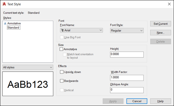
FIGURE 13-1: Text — with style.
Taking Your Text to New Heights
Drawing scale is the traditional way to describe a scale with an equal sign or colon — for example, 1/4" = 1'-0", 1:20, or 2:1. The scale factor represents the same relationship with a single number, such as 48, 20, or 0.5. The drawing scale factor is the multiplier that converts the first number in the drawing scale into the second number.
You must determine the scale factor of a drawing before you add non-annotative text to it.
Plotted text height
Most industries have plotted text height standards, which AutoCAD refers to as paper text height. A plotted text height of 1/8" or 3mm is common for notes. Some companies use slightly smaller heights (for example, 3/32" or 2.5mm) to squeeze more text into small spaces.
Calculating non-annotative AutoCAD text height
To calculate non-annotative text height, you need to know the drawing scale factor, the desired plotted text height, and the location of the multiplication button on your calculator. Follow these steps to calculate the text height:
-
Determine the drawing scale factor.
Drawing scale is based on the size of the object you’re drawing versus the size of the sheet of paper on which it will be printed. For example, a house floor plan would have to be scaled down 1:96 (1/8″=1′) to fit an A-size sheet, whereas a watch gear would have to be scaled up 50:1 to appear as more than a dot in the middle of the sheet. As noted, the drawing scale factor is the inverse of the drawing scale: 96 for the house plan, and 1/20 or 0.05 for the watch gear.
You shouldn’t select a scale factor at random. Different industries have lists of “preferred” (which you should read as “mandatory”) scale factors, and individual companies in turn may have a short list within the preferred values. When you edit an existing drawing, it should have a bar scale or text note indicating the drawing scale. If not, and if the drawing dimensions are in model space, you can check the value of the DIMSCALE variable (the system variable that controls dimension scale), as described in Chapter 14, or work backward from existing text sizes. -
Determine the height at which notes should appear when you plot the drawing to scale.
See the earlier section “Plotted text height” for suggestions.
-
Multiply the numbers resulting from Steps 1 and 2.
After you know the AutoCAD text height, you can use it to define the height of a text style or of an individual text object.
If you assign a nonzero height to a text style (refer to Step 7 in the earlier section “Get in style”), all text that you create in that style uses the fixed height. If you leave the text style’s height set to 0 (zero), AutoCAD asks you for the text height every time you draw single-line text objects, which soon becomes a real nuisance.
This discussion of text height assumes that you’re adding non-annotative text in model space. In addition to annotative text in model space, you have a third alternative: Add annotative or non-annotative text to a paper space layout — for example, when you draw text in a title block or add a set of sheet notes that doesn’t directly relate to the model space geometry. When you create text in paper space, you specify the actual, plotted paper height instead of the scaled-up height. (I cover paper space in Chapter 12.)
Entering Text
AutoCAD offers two different kinds of text objects and two corresponding text-drawing commands:
 Single-line text: TEXT (DT). Designed to create single lines. Although you can press Enter to create more than one line of text, each line becomes a separate text object. Text doesn’t wrap if you add or remove anything.
 Paragraph text: MTEXT (T): Designed to create multiple lines, with word-wrapping. AutoCAD groups multiple lines as a single object. Other special formatting, such as on a numbered or bulleted list or column, is possible. The mText command basically launches a small word processor.
Although you may be inclined to ignore the older, single-line text option, you should know how to use both kinds of text. The TEXT command is quite a bit simpler to use than the mText command, and it’s still useful for entering short, single-line pieces of text such as object labels and one-line notes. It’s also the command of choice for CAD comedians who want to document their one-liners!
Both the TEXT and mText commands offer a full array of text justification options — the way the text flows from the point or points that you pick in the drawing to locate it. For most purposes, the default left justification (for single-line text) or top-left justification (for paragraph text) works fine. Occasionally, you may want to use a different type of justification, such as center, for labels or titles. Both commands provide options for changing the text justification.
Using the Same Old Line
Despite its limitations, the TEXT command is useful for labels and other short notes for which mText (multiline) would be overkill. The following steps show you how to add text to a drawing by using AutoCAD’s TEXT command.
The TEXT command doesn’t use a dialog box, fancy formatting toolbar, or contextual Ribbon tab, like the mText command’s In-Place Text Editor. You set options by typing them in the command line or in the Dynamic Input tooltip.
Here’s how to add text by using the TEXT command:
-
Set an appropriate non-annotative text style current, as described in the section “Simply stylish text,” earlier in this chapter.
It’s possible to set an already created text style current at the TEXT command prompt, but it’s usually more straightforward to set the style before starting the command.
An alternative to opening the Text Style dialog box to make an existing style current is to click the Text Style drop-down list and choose the style there. Look for the Text Style drop-down list on the Annotation panel’s slideout (on the Home tab) or on the Text panel of the Annotate tab.If you know the name of the text style that you want to use, begin typing it at the command line. The AutoCAD command line searches for text styles; they appear at the bottom of the command line window. When you see the one you want, just select it.
-
(Optional) Use the Object Snap button on the status bar to enable or disable running object snaps.
You may or may not want to snap text to existing objects. For example, you’d want to use a Center object snap to locate a letter or number precisely at the center of a circle. Make sure that you specify middle-center (MC) text justification to ensure that object snapping works perfectly.
-
On the Home tab’s Annotation panel, click the lower part of the big button labeled Text, and then choose Single Line from the drop-down menu to start the TEXT command.
Don’t click the upper part of the Text button. That action starts the multiline text command, mText, which I cover in the later section, “Saying More in Multiline Text.”
If your text style is annotative and this annotative object is the first one you’re creating in this drawing session, AutoCAD usually displays the Select Annotation Scale dialog box, which advises you that you are indeed creating an annotative object and asks you to set the scale at which you want the annotation to appear; click OK to continue. Later, I explain how and why to turn off this annoying dialog box.
AutoCAD tells you the current text style and height settings and then prompts you to either select a starting point for the text or choose an option for changing the text justification or current text style first:
Current text style: "Standard" Text height: 0.2000 Annotative: NoSpecify start point of text or [Justify/Style]: -
If you want a justification style different from the default (left), type J, press Enter, and choose another justification option.
Look up the term create single-line text in the online Help system if you need help with the justification options.
-
Specify the insertion point for the first text character.
You can enter the point’s coordinates from the keyboard, use the mouse to click a point onscreen, or press Enter to locate new text immediately below the most recent single-line text object that you created.
AutoCAD prompts you for the text height:
Specify height <0.2000>: -
Specify the height of the text.
The text height prompt doesn’t appear if you’re using a text style with a fixed (that is, nonzero) height. See the “Creating Simply Stylish Text” section, earlier in this chapter, for information about fixed-versus-variable text heights. Now here’s the nuisance: If you haven’t specified a fixed height for the current text style, you’ll be asked for the text height every time you create text, and you’ll have to enter the correctly scaled value to get things to come out right.AutoCAD prompts you for the text rotation angle:
Specify rotation angle of text <0>: -
Specify the text rotation angle by typing the rotation angle and pressing Enter or by rotating the line onscreen with the mouse.
AutoCAD prompts you to type the text.
- Type the first line of text and press Enter.
-
(Optional) Type additional lines of text, pressing Enter at the end of each line.
Each line of text is neatly aligned below the previous line and is a separate, independent object and cannot be edited as a single paragraph. If you want a single paragraph, use the mText command.
-
To stop entering text and return to the command line, press Enter at the start of a blank line.
AutoCAD adds to the drawing the new, single-line text object — or objects, if you typed more than one line.
The TEXT command remembers its last-used settings (style, justification, height, and rotation angle), so you don’t need to reapply them every time.
If your text will occupy more than one line, it is better to use mText, covered later in the chapter.
To edit single-line text, double-click it to open the In-Place Text Editor.
The in-place editing box highlights the selected text object, enabling you to edit the contents of the text string. If you want to edit other text properties such as text height, select the text, right-click, and choose Properties to display the Properties palette. Use this palette to change properties as needed.
If the Quick Properties button on the application status bar is enabled, clicking a single-line text object opens the Quick Properties panel, allowing you to change some (but not all) of the same properties as you can on the Properties palette.
Saying More in Multiline Text
When you just can’t shoehorn your creative genius into one or more one-line pieces of text, AutoCAD’s multiline text object gives you room to go on and on and on. The following sections show you how to create multiline text with the mText command.
Making it with mText
The first part of the mText command prompts you for various points and options. Read the prompts carefully to avoid confusion.
Here’s how to use the mText command:
-
Set an appropriate text style current, and (optional) turn off running object snaps, as described in Steps 1 and 2 in the “Using the Same Old Line” section, earlier in this chapter.
Make sure to also set an appropriate layer current before creating the text object.
-
On the Home tab’s Annotation panel, click the upper part of the split button, labeled Text, to start the mText command.
The command line displays the current text style and height settings and prompts you to select the first corner of an imaginary rectangle that determines the word-wrapping width of the text object:
Current text style: "Standard" Text height: 0.2000 Annotative: NoSpecify first corner: -
Pick a point in the drawing.
The command line prompts you for the opposite corner of a rectangle that will determine the word-wrapping width; it also gives you the option to change settings first:
Specify opposite corner or [Height/Justify/ Line spacing/Rotation/Style/Width/Columns]: -
Type H and press Enter to change the default text height.
The command line prompts you for a new default text height if the current text style has a height of 0.0:
Specify height <0.2000>: -
If applicable, type an appropriate text height.
See the “Taking Your Text to New Heights” section, earlier in this chapter, for information. If you’re adding text in model space, I highly recommend that you use annotative text.
The prompt for the opposite corner of the mText rectangle reappears. The command line displays:
Specify opposite corner or [Height/Justify/ Line spacing/Rotation/Style/Width/Columns]: -
If you want a different justification from the default (top left), type J, press Enter, and choose another justification option.
Enter justify multiline text in the Search box of the online Help system if you want an explanation of the other justification options.
-
Pick another point in the drawing.
Don’t worry about the height of the rectangle that you create by choosing the second point; the width of the rectangle is all that matters. AutoCAD adjusts the height of the text rectangle to accommodate the number of lines of word-wrapped text. Don’t worry too much about the width, either, because you can adjust it later.The In-Place Text Editor window appears with the tab and indent ruler above it (as shown in Figure 13-2), and the previously hidden Text Editor contextual tab appears on the Ribbon.
When you create multiline text in either AutoCAD or AutoCAD LT, text objects default to Dynamic Column mode. As I indicate earlier, the initial selection window primarily sets the width. By default, if you enter enough text to fill the window, mText defaults to splitting the text into two columns, as in a newspaper. If you don’t like this arrangement, you can dynamically stretch the text editor window to become wider or longer.If you never want to use columns in the current drawing, click Columns in the Insert panel of the Text Editor tab, which appears only when you're creating or editing multiline text. This action sets the MTEXTCOLUMN system variable to 0. It affects only the current drawing, so if you never want columns, set it up in your template drawings. (I cover templates in Chapter 4.)
-
Verify the text font and height.
The text font and height should be correct if you properly completed Steps 1, 4, and 5. If you didn’t, you can change these settings in the Font drop-down list and the Text Height text box on the Text Editor tab (or on the classic Text Formatting toolbar).
-
Type text into the text area of the In-Place Text Editor.
AutoCAD automatically word-wraps and extends the text box downward as you add more text. If you want to force a line break at a particular location, press Enter.
You can copy and paste from other applications, such as Word documents. -
If you want to set other formatting options, select text, right-click, and make an appropriate choice from the menu, as shown in Figure 13-3.
By convention in most industries, text in drawings is always uppercase. To always have your notes in uppercase, right-click in the In-Place Text Editor and choose AutoCAPS from the menu. -
Click Close Text Editor on the Ribbon or OK on the classic Text Formatting toolbar.
The In-Place Text Editor window closes, and AutoCAD adds your text to the drawing.
You can close the text editor much more easily by simply clicking outside its window. But if you like clicking buttons instead, AutoCAD has amply provided for you. -
If you set an annotative text style current in Step 1, assign an annotation scale to the multiline text object.
See the “Turning on Annotative Objects” section, later in this chapter.

FIGURE 13-2: Adding immortal multiline text.

FIGURE 13-3: Right-click your way to textual excellence.
You can easily change the layout of text. Simply double-click the text and then use grip editing to change the width or height of the text box. If you make the box too short to hold all the text, AutoCAD automatically splits it into side-by-side newspaper-style columns as needed.
As you can tell by looking at the Text Editor tab (or the Text Formatting toolbar) and multiline text right-click menu, the mText command gives you plenty of other options. You can show or hide the toolbar, the ruler, or the Options buttons, and you can give the In-Place Text Editor an opaque background. Other tool buttons give you access to columns and numbered or bulleted lists. Both covered in the section “Doing a number on your mText lists,” later in this chapter.
Between them, the Text Editor tab (or the Text Formatting toolbar) and the right-click menu also include a Stack/Unstack feature for fractions, a Find and Replace utility, tools for toggling lowercase and uppercase, options for applying background masks and inserting fields, a special Symbol submenu, and an Import Text option for importing text from a TXT (ASCII) file or RTF (Rich Text Format) file. (I discuss background masks and fields in the next section.) If you think you can use any of these other features, choose Resources ⇒ Commands ⇒ mText in AutoCAD’s online Help browser to find out more about them.
mText dons a mask
When you turn on background masking, AutoCAD hides the portions of any objects that lie under the multiline text. This feature is used primarily when adding text to an area that has already been crosshatched. I cover hatching in Chapter 15. Use these steps to turn on, and control, this feature:
-
Right-click in the In-Place Text Editor and choose Background Mask from the menu.
The Background Mask dialog box appears.
- Mark the Use Background Mask check box so that this option is turned on.
- Either click Use Drawing Background Color to make the mask the same color as the drawing area’s background color or choose a color from the drop-down list to make the text appear in a solid rectangle of the specified color.
- Click OK to return to the In-Place Text Editor.
If you’ve turned on background masking but it isn’t having the desired effect, use the TEXTTOFRONT command to move the text on top of other objects. Click the Bring to Front drop-down button on the Home tab’s Modify panel slideout, and choose Bring Text to Front.
Insert Field
The Insert Field option on the In-Line Text Editor’s right-click menu creates a text field that updates automatically every time you open, save, plot, or regenerate the drawing. Fields can contain data such as the date, filename, or author’s name. Fields draw information from the operating system settings, Drawing Properties dialog box, sheet sets feature (not covered in this book), AutoCAD system variables (see Chapter 23), and specific drawing object properties, such as the circumference of a circle or the area enclosed by a closed polyline. Follow these steps to add a field while you’re creating multiline text:
-
Right-click in the In-Place Text Editor and choose Insert Field from the menu.
The Field dialog box appears.
- Choose a Field Name in the left column.
- Choose a Format in the right column or, for date fields, type a format in the Date Format box.
-
Click OK.
AutoCAD adds the field to the mText object that you’re creating or editing.
Doing a number on your mText lists
The mText command supports bulleted and numbered lists. This feature is especially useful for creating general drawing notes, as shown in Figure 13-4.

FIGURE 13-4: Tabs, indents, and automatic numbering are set to create numbered lists.
AutoCAD automates the process of creating numbered lists almost completely. Follow these steps:
- Follow Steps 1–8 in the earlier section, “Making it with mText,” to open the In-Place Text Editor.
-
Type a title (for example, DESIGN CRITERIA).
If you want the title underlined, click Underline on the Formatting panel before you type the title; click Underline again to turn it off. Press Enter to go to the next line, and press Enter again to leave a little more space.
-
On the Paragraph panel of the Text Editor tab, click the Bullets and Numbering drop-down button; verify that Allow Auto-List, Use Tab Delimiter Only, and Allow Bullets and Lists are selected; then click Numbered, as shown in Figure 13-4.
The number
1followed by a period appears on the current line, and the cursor jumps to the tab stop that’s visible on the ruler, at the top of the In-Place Text Editor window. Enabling the Numbered option places numerals followed by periods in front of items in a list. The Bulleted option places bullet characters in front of items in a list. Allow Auto-List enables automatic numbering; every time you press Enter to move to a new line, AutoCAD increments the number. -
Type the text corresponding to the current number or bullet.
As AutoCAD wraps the text, the second and subsequent lines align with the tab stop, and the text is indented automatically.
-
Press Enter at the end of the paragraph to move to the next line.
As with creating numbered lists in your favorite word processor, AutoCAD automatically inserts the next number at the beginning of the new paragraph, with everything perfectly aligned.
To create nested numbered or bulleted items (as shown in Figure 13-4), simply press Tab at the start of the line. If you change your mind, you can bump up a nested text item up one level by selecting the item in the In-Place Text Editor and pressing Shift+Tab. -
Repeat Steps 4 and 5 for each subsequent numbered or bulleted item.
For legibility, you sometimes add spaces between the notes. If you press Enter twice to add a blank line, AutoCAD — like every good word processor — thinks you’re finished with the list and turns off numbering. AutoCAD is smart, so you need to be smarter. If you put the cursor at the end of the first note and press Enter, you get a blank line. The problem is, the blank line is now numbered, and the intended Note 2 is now Note 3. Just press the Backspace key. The number on the blank line disappears, and Note 2 is back to being Note 2. When you delete a numbered item, the remaining numbers adjust automatically.If you don’t like the horizontal spacing of the numbers or the alignment of subsequent lines, you can adjust them easily by manipulating the tab and indent markers in the In-Place Text Editor’s ruler.
-
In the ruler, drag the upper slider (the triangle pointing down) to the right a short distance. Drag the lower slider (the triangle pointing up) a slightly greater distance to the right.
The upper slider controls the indentation of the first line in each paragraph. The lower slider controls the indentation of the second and subsequent lines. An indent of one to two of the short, vertical tick marks usually works well for the first line. An indent of two to four tick marks works well for the second and subsequent lines.
-
Click in the ruler just above the lower slider.
A small L appears above the lower slider. The L shows the left-justified tab stop.
Make sure that the corner of the L aligns horizontally with the point of the lower slider triangle. If not, click and drag the L until it aligns.
If you prefer to manually enter tab and indent distances (rather than adjust them with the cursor), open the Paragraph dialog box by either
- Clicking the little arrow at the right end of the Paragraph panel label (in AutoCAD-ese, it’s a Panel dialog box launcher)
- Right-clicking inside the In-Place Text Editor and choosing Paragraph
Whichever way you do it, if you select text first, the tab and indent changes apply to the selected text. If you don’t select text first, the changes apply to new text from that point forward in the multiline text object.
Line up in columns — now!
The text functionality of AutoCAD is becoming more word processor-like. A few releases back, it was simple indents, and then came numbered and bulleted lists. The most recent addition to multiline text is columns.
Columns come in two flavors:
- Static: You specify the number of columns into which you want text to flow. Columns are always the same height, and text is allowed to overflow the final column if there’s too much of it.
- Dynamic: As you might expect, these columns are friendlier and more flexible, and they’re the life of any party. You can individually adjust column heights, and new columns are added automatically to accommodate the text.
Selecting either column type also offers you the Column Settings dialog box, where you can specify values numerically rather than drag grips. Figure 13-5 shows a block of multiline text imported as an RTF file from a word processor and then formatted in dynamic columns using the Manual Height option.
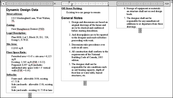
FIGURE 13-5: Dynamically columnizing the text.
Setting up columns is straightforward, as these steps explain:
-
Open a drawing that contains a large, multiline text object, or create a large, multiline text object in a new drawing.
If you already have drawing specifications or general notes in a word processing document, or even in a text file, you can right-click inside the mText command’s In-Place Text Editor and choose Import Text. The Select File dialog box opens, giving you the choice of Rich Text Format (RTF) or ASCII text (TXT) files. - If the In-Place Text Editor isn't already open, either double-click the text; or select it, right-click, and choose Mtext Edit.
-
Click Columns in the Insert panel and choose either Dynamic Columns or Static Columns.
If you choose Dynamic Columns, select either Auto Height or Manual Height. Selecting Manual Height puts grips on each column so that you can adjust their height individually (refer to Figure 13-5). Auto Height displays a single grip so that the heights of all columns remain the same, but new columns are still added as required by the amount of text.
If you choose Static Columns, select the number of columns you want from the menu. Clicking 2, for example, creates two columns regardless of the length of the text. You may end up with overflowing text or empty columns.
-
Click Close Text Editor on the Ribbon (or OK on the Text Formatting toolbar) when you’re satisfied with the column arrangement.
You can revert to a noncolumnar arrangement by clicking the Columns button in the Insert panel and choosing No Columns.
Modifying mText
After you create a multiline text object, you can edit it in the same way as a single-line text object: Select the object, right-click, and choose Mtext Edit or Properties.
- Mtext Edit: Selecting this option opens the In-Place Text Editor window so that you can change the text contents and formatting.
- Properties: Selecting this option opens the Properties palette, where you can change the overall properties of the text object.
- Quick Properties: Enable this setting on the status bar so that when you select a multiline text object, the Quick Properties palette opens, in which you can modify a subset of the mText object’s properties.
The easiest way to change the word-wrapping width of a paragraph text object is to grip-edit it. Select the text object, click a corner grip, release the mouse button, move the cursor, and click again. Chapter 11 describes grip-editing in detail.
![]()
![]() Just like any good word processor or text editor, AutoCAD includes both a spel chekcqing and a find-and-replace tool for text. To check the spelling of selected annotation objects or the entire drawing, click the Annotate tab on the Ribbon and choose Check Spelling from the Text panel to display the Check Spelling dialog box. On the same panel, clicking Find Text (or typing FIND and pressing Enter) displays the Find and Replace dialog box. Handily, both Find and Replace and Spell Check are also accessible from the Text Editor tab’s Spell Check and Tools panels, in case you want to replace text or check spelling within a single multiline text object. Look up SPell or FIND in the online Help system if you need more information on either command.
Just like any good word processor or text editor, AutoCAD includes both a spel chekcqing and a find-and-replace tool for text. To check the spelling of selected annotation objects or the entire drawing, click the Annotate tab on the Ribbon and choose Check Spelling from the Text panel to display the Check Spelling dialog box. On the same panel, clicking Find Text (or typing FIND and pressing Enter) displays the Find and Replace dialog box. Handily, both Find and Replace and Spell Check are also accessible from the Text Editor tab’s Spell Check and Tools panels, in case you want to replace text or check spelling within a single multiline text object. Look up SPell or FIND in the online Help system if you need more information on either command.
Turning On Annotative Objects
Annotative objects were introduced in AutoCAD 2008, ending 25 years of calculation agony, but a quick show of hands in classes at Autodesk University and AUGI CAD Camp reveals that only 20 percent of students, on average, have ever tried using annotative objects — and most of the students abandoned them to return to the old way, in the belief that they weren’t working. I provide an explanation in a moment.
Make sure that you’re in model space, and follow these steps to enable the use of annotative scaling for new or modified annotation objects.
-
Set the Annotation controls.


 In the lower-right corner of the AutoCAD status bar, you find three buttons with variants of a triangular symbol. They represent the end view of an engineer’s triangular scale; an old-timer in your office should be able to show you one and how they worked. If the person has a rubber band in the other hand, be ready to duck. Click the Annotation Visibility (middle) and Automatically Add Scales to Annotative Objects (right-hand) buttons, until they’re grayed out and don’t show a small, yellow splash in them. If the Annotation Scale (left-hand) button doesn't display the scale 1:1, click it and select 1:1 from the drop-down list.
 -
Select an annotative text style.
Use the STyle command as described in the earlier section “Get in style,” and set the Annotative text style current. Set its paper text height to 0.125.
-
Create a text object.
Use the TEXT command and create a line of text that says Scale 1:1.
The first time you place annotative text, you’re asked to select a drawing scale, and it defaults to the current scale, which is probably what you want anyway. Eventually, it becomes a nuisance, so the check box lets you turn it off.
-
Change the drawing scale.
Click the Annotation Scale (left-hand) button and choose 1:2 from the drop-down list. This step sets the current drawing scale to 1:2. Hey, the first piece of text disappears! Not to worry — that’s what it’s supposed to do.
-
Create a text object.
Use the TEXT command again to create a line of text that says Scale 1:2, and another one that says Both scales. Note that they’re twice as tall as the now-invisible Scale 1:1 text, even though you didn’t specify a height.
-
Change the drawing scale.
Click the Annotation Scale (left-hand) button and choose 1:1 from the drop-down list. Interesting! The first piece of text reappears, but the other two disappear!
-
Add another scale to an object.
Click the Annotation Scale (left-hand) button and choose 1:2 from the drop-down list. Then click the Both scales text and right-click. Choose Annotative Object Scale and then choose Add/Delete Scales. When the dialog box appears, click the Add button in the upper-right corner and then choose 1:1 from the list. Click OK, and then click OK again to return to the drawing screen.
-
Change the drawing scale.
Click the Annotation Scale (left-hand) button and choose 1:1 from the drop-down list. Interesting! The Scale 1:1 text reappears, Scale 1:2 disappears, and the Both scales size changes to match the height of the Scale 1:1 text!
-
Change the drawing scale again.
Click the Annotation Scale (left-hand) button and choose 1:5 from the drop-down list. All three text items disappear!
Here’s what I want you to remember about annotative objects:
-
Upon creation, annotative objects automatically size themselves to suit the current drawing scale; they’re visible only when their annotation scales match the current drawing scale; and they can have more than one scale attached, so they’re visible in more than one drawing scale setting.
Better yet, they exhibit this same behavior in paper space viewports. It thus becomes trivially easy to set up drawings with details at other scales. I cover this topic in more detail in Chapter 15.
- If an annotative object has multiple scales attached and you edit its location at one scale, its location at the other scales isn’t affected.
- When viewing an object with multiple scales, you aren’t looking at multiple objects but rather at a single object with multiple representations. To see what I mean about different representations, change the text string of the Both scales text object that you created earlier to a different value. The new value automatically appears in all scale representations for that text object.
Now I reveal the dirty, dark secret of why most people give up on annotative objects. It all goes back to the annotative controls:
- When the Annotation Visibility (middle) button is turned on, all the annotative objects at all scales are always visible, regardless of the value of the current drawing scale, even if none of the objects has a scale that matches the current drawing scale. You should only turn this option on when you want to move the different representations of your annotative objects around onscreen.
- If you turn on the Automatically Add Scales to Annotative Objects (right-hand) button and then change the drawing scale, every annotation object retroactively gets the current scale added to it. This is not something you want to do except in the situation of when you create a drawing to print at a specific scale and then decide to change the scale to suit a different printer or paper size.
By themselves, both options can give you some headaches, but if both options are enabled at the same time and you switch the current scale it is not obvious that you might have accidentally added the current scale to all the annotative objects in your drawing.
Most of the time, for most people, there are way too many scales listed in the Add Scales to Object dialog box. AutoCAD has a handy-dandy Edit Drawing Scales dialog box that lets you remove those imperial scales from the current drawing if you never work in feet and inches. And vice versa, for the metrically challenged. To run through the scales, choose Scale List on the Annotation Scaling panel of the Ribbon’s Annotate tab. If you make a mistake, pressing the Reset button restores all default scales. You can remove those extra scales for all drawings in the Default Scale List dialog box, accessible from the User Preferences tab of the Options dialog box.
Figure 13-6 shows two views of the same drawing. The hatching and the 1.400 dimension were created once but have resized themselves to appear correctly in the two views at two different scales.

FIGURE 13-6: Annotative objects resize automatically as the annotation scale changes.
Gather Round the Tables
You don’t know the meaning of the word tedious unless you’ve tried to create a column-and-row data table in older versions of AutoCAD by using the Line and TEXT commands. AutoCAD’s table object, and the TABLESTYLE and TABLE commands for creating it, make the job almost fun.
Table objects in AutoCAD are not annotative, so you have just two methods of adding them to drawings: Create them in model space, scaling them up by the drawing scale factor (see Chapter 4 for more) or — this one seems more sensible — create them in paper space, defining them by their actual plotted (paper) dimensions.
Tables have style, too
You control the appearance of tables — both text and cells — with table styles just as you control the appearance of stand-alone text by using text styles. Use the TABLESTYLE command to create and modify table styles. Follow these steps to create a table:
-
 On the Home tab, click the Annotation panel’s label to open its slideout, and then choose Table Style.
The Table Style dialog box appears.
-
In the Styles list, select the existing table style whose settings you want to use as the starting point for the settings of the new style.
For example, select the default table style named Standard.
-
Click New to create a new table style that’s a copy of the existing style.
The Create New Table Style dialog box appears.
-
Enter a new style name and click Continue.
The New Table Style dialog box appears, as shown in Figure 13-7.
-
In the Cell Styles area, with Data showing in the list box, specify settings for the data alignment, margins, text, and borders.
The settings you’re likely to change are Text Style, Text Height, and perhaps Text Color. All three are on the Text tab. Grid Color is on the Borders tab. If you leave colors set to ByBlock, the text and grid lines inherit the color that’s current when you create the table. That color will be the current layer’s color.
- In the Cell Styles area, open the drop-down list and repeat Step 5 for the Headers (that is, the column headings) and the Title styles.
-
Click OK to close the New Table Style dialog box.
The Table Style dialog box reappears.
-
Click Close.
The new table style becomes the current table style that AutoCAD uses for future tables in this drawing, and the Table Style dialog box closes. Now you’re ready to create a table, as described in the next section.

FIGURE 13-7: Setting the table.
You can access the Manage Cell Styles dialog box directly from the Cell Styles drop-down list of the New Table Style dialog box. The Table Cell Format dialog box (on the General tab, in the Format row, click the ellipsis button) provides a number of additional options for formatting cells by data type.
AutoCAD stores table styles in the DWG file, so a style that you create in one drawing isn’t immediately available in others. You can copy a table style from one drawing to another using DesignCenter. Use the steps for copying layers between drawings that I outline in Chapter 9, but substitute Tablestyles for Layers. Table styles can also be defined in drawing template files, which I discuss in Chapter 4.
Creating and editing tables
After you create a suitable table style, adding a table to a drawing is easy, with the TABLE command. Here’s how:
-
Set an appropriate layer current.
Assuming that you leave the current color, linetype, and lineweight set to ByLayer, as I recommend in Chapter 9, the current layer’s properties control the properties of all table parts that were set to ByBlock when in the assigned table style. Refer to Step 5 in the preceding section, “Tables have style, too.”
-
 On the Home tab’s Annotation panel, click Table.
The Insert Table dialog box appears.
- Choose a table style from the Table Style drop-down list.
- Choose an insertion behavior:
- Specify Insertion Point: Pick the location of the table’s upper-left corner; use the lower-left corner instead if you set Table Direction to Up in the table style. When you use this method (the easiest), you specify the default column width and number of rows in the Insert Table dialog box.
- Specify Window: Pick the upper-left corner and then the lower-right corner. When you use this method, AutoCAD automatically scales the column widths and determines how many rows to include.
- Specify column and row settings.
- If you chose Specify Insertion Point in Step 4, you must set the number of columns and data rows that the table should be created with along column width and row height.
- If you chose Specify Window in Step 4, AutoCAD sets the column width and the number of data rows to Auto. AutoCAD then figures them out, basing those values on the overall size of the table that you specify in Steps 7 and 8. While AutoCAD calculates the column width and number of data rows to use for the table automatically, you must still specify the number of columns and row height values to create the table.
-
Click OK.
AutoCAD prompts you to specify the insertion point of the table.
-
Click a point or type coordinates:
- If you chose Specify Insertion Point in Step 4, AutoCAD draws the table gridlines, places the cursor in the title cell, and displays the Text Editor tab on the Ribbon.
- If you chose Specify Window in Step 4, specify the diagonally opposite corner of the table.
AutoCAD draws the table based on the table size you indicated and chooses the column width and number of rows.
- Type a title for the table.
-
Type values in each cell, using the arrow keys or Tab key to move among cells.
The cell right-click menu offers many other options, including copying contents from one cell to another, merging cells, inserting rows and columns, changing the formatting, and inserting a block which is a graphical symbol; see Chapter 17 for information about blocks.
You can insert a field into a table cell. For example, you might create part of a title block, with fields serving as the date and drawn by data. -
Click Close Text Editor on the Ribbon or click OK on the Text Formatting toolbar.
Figure 13-8 shows a completed table, along with the Insert Table dialog box.

FIGURE 13-8: The Insert Table dialog box and one result of using it.
Edit the cell values by double-clicking in a cell. To change the column width or row height, click the table grid and then click and move the blue grips. To change the width of one column without altering the overall width of the table, hold down the Ctrl key while you move the grip. If you want to change other aspects of a table or individual cells in it, select the table or cell and use the Quick Properties palette or the Properties palette to make changes.
The DATAEXTRACTION and DATALINK commands are powerful tools in AutoCAD. You can use them to link all or part of an Excel spreadsheet into a table in a drawing; or interrogate a drawing to produce a great variety of information from it (such as sizes, areas, perimeters, and quantities of drawing objects) and then create a linked table of the data; or write the data to an Excel spreadsheet — or all three options at once. A detailed description of these functionalities is beyond the scope of this book, but several online references are available that cover them. These two can get you started:
Take Me to Your Leader
Don’t worry — I’m not a space alien, popular opinion to the contrary. No, I’m talking about notes with arrows pointing to drawing objects that you need to embellish with some verbiage.
Multiline leaders (mleaders, for short) are a vast improvement over the old-style leaders, available in releases before AutoCAD 2008. In fact, they’re so good that they should be running the United Nations! MLeaDers, unlike the old-style leaders, are single objects. They can also point in multiple directions at a time; just don’t ask them which way is the bus station. Finally, multileaders — just like text, dimensions, hatching, and other objects you use to document drawings — can be annotative.
Electing a leader
You can draw multileader objects that consist of leader lines and multiline text at the same time by using the MLeaDer command; follow these steps:
-
Set a multileader style that’s appropriate for your needs.
 Choose an existing style from the Multileader Style drop-down list on the Home tab’s Annotation panel slideout, or create a new style by clicking the Multileader Style button on the Annotation slideout. Visit the online Help system for tips on creating new multileader styles.
 -
 Choose Multileader from the Annotation panel.
The command line prompts you to select the location of the pointy end of the leader arrowhead:
Specify leader arrowhead location or [leader Landing first/Content first/Options] <Options>:The initial default method is to locate the arrowhead, followed by the leader landing (that is, the short horizontal line between the leader line and the text), at which point AutoCAD displays the In-Place Text Editor and you enter the text of your note. If you’d rather place the leader landing first, type L and press Enter. If you’d rather type the content first, type C and press Enter.
If you want to draw spline-curved rather than straight leader lines, specify the number of pick points for the leader lines and press Enter to display multileader options at the command line or the Dynamic Input tooltip. Refer to the online Help for more information on the command options.
-
Pick a location in the drawing that you want the leader to point to.
If you use an object snap mode, such as NEArest or MIDpoint, to pick a point on an object, AutoCAD associates the leader with the object. If you later move the object, AutoCAD updates the leader so that it points to the new location.
The command line prompts you for the next point.
-
Pick a second point.
AutoCAD draws a shaft from the arrowhead to this point.
Don’t pick a second point that’s too close to the arrowhead point. If AutoCAD doesn’t have enough room to draw the arrowhead, it omits the arrowhead.By default, AutoCAD lets you pick two points for the leader line: The first point locates the arrowhead, and the second point locates the start of the short horizontal leader landing. If you need more points than that, restart the command and choose Options, Maxpoints and set a new value. After you pick the point for the leader landing, the In-Place Text Editor opens.
-
Type your text.
You’re now in the same In-Place Text Editor I describe earlier in this chapter, with the same Text Editor tab and options.
-
Click Close.
Your text is added to the drawing, next to the leader.
Figure 13-9 shows several different leaders with notes.

FIGURE 13-9: No loss for (multi)leaders.
You can use grips to manipulate a multileader’s individual components, just as if it were several objects instead of a single object. Hold down the Ctrl key and click a multileader to select different pieces. You can even use grips to adjust the width of multileader text as if it were an everyday mText object.
Multi options for multileaders
In addition to using the MLeaDer command itself, multileaders come with a slew of formatting, drawing, and editing commands:
- MLeaderEdit: Use this command to add or remove leader lines from multileader objects. You’ll find each of those functions on the Multileader drop-down list (refer to Figure 13-9).
- MLeaderStyle: Multileaders, like text and dimensions, are formatted according to named styles. To display the Multileader Style Manager dialog box, click Multileader Style on the Home tab’s Annotation slideout.
- MLeaderAlign: A tedious chore in earlier AutoCAD versions was making all the leaders line up by using a construction line and then using object snaps to move common points on the leaders to the construction line. To line up multileaders, choose Align from the Multileader drop-down list.
- MLeaderCollect: Multileaders can contain blocks as well as text. I cover blocks in Chapter 17. Choose Collect from the Multileader drop-down list to gather a group of leaders containing blocks; they’ll rearrange themselves as a single multileader containing the multiple blocks.
For more information on any of these commands, look them up by name in the Command Reference section of the online Help system.
Multileaders and multileader styles can be annotative or non-annotative. Making them annotative and assigning appropriate annotation scales is a huge timesaver for creating them initially and for creating detail views at different scales.