Chapter 8
NC Part Programming
8.1 Introduction
Numerical control part programming is the procedure by which the sequence of processing steps to be performed on the NC machine is planned and documented. It involves the preparation of a punched tape (or other input medium) used to transmit the processing instructions to the machine tool. As indicated in Section 7.3, there are two methods of part programming: manual part programming and computer-assisted part programming. In this chapter we describe both of these methods, with emphasis on the latter.
It is appropriate to begin the discussion of NC part programming by examining the way in which the punched tape is coded. Coding of the punched tape is concerned with the basic symbols used to communicate a complex set of instructions to the NC machine tool. In numerical control, the punched tape must be generated whether the part programming is done manually or with the assistance of some computer package. With either method of part programming, the tape is the net result of the programming effort. In Sections 8.2 and 8.3 our attention will be focused on the punched tape and the structure of the basic language used by the NC system.
8.2 The Punched Tape in NC
The part program is converted into a sequence of machine tool actions by means of the input medium, which contains the program, and the controller unit, which interprets the input medium. The controller unit and the input medium must be compatible. That is, the input medium uses coded symbols which represent the part program, and the controller unit must be capable of reading those symbols. The most common input medium is punched tape. The tape has been standardized so that tape punchers are manufactured to prepare the NC tapes, and tape readers (part of the controller unit) can be manufactured to read the tapes. The punched tape used for NC is 1 in. wide. It is standardized as shown in Figure 8.1 by the Electronics Industries Association (EIA), which has been responsible for many of the important standards in the NC industry.
There are two basic methods of preparing the punched tape. The first method is associated with manual part programming and involves the use of a typewriterlike device. Figure 8.2 illustrates a modern version of this kind of equipment. The operator types directly from the part programmer’s handwritten list of coded instructions. This produces a typed copy of the program as well as the punched tape. The second method is used with computer-assisted part programming. By this approach, the tape is prepared directly by the computer using a device called a tape punch.
By either method of preparation, the punched tape is ready for use. During production on a conventional NC machine, the tape is fed through the tape reader
Figure 8.1 Numerical control punched tape format as standardized by Electronic Industries Association. (Reprinted fron Childs [2].)

Figure 8.2 Equipment used to prepare punched tape for NC. (Courtesy of NumeridexCorp.)

once for each workpiece. It is advanced through the tape reader one instruction at a time. While the machine tool is performing one instruction, the next instruction is being read into the controller unit’s data buffer. This makes the operation of the NC system more efficient. After the last instruction has been read into the controller, the tape is rewound back to the start of the program to be ready for the next workpart.
8.3 Tape Coding and Format
NC tape coding
As shown in Figure 8.1, there are eight regular columns of holes running in the lengthwise direction of the tape. There is also a ninth column of holes between the third and fourth regular columns. However, these are smaller and are used as sprocket holes for feeding the tape.
Figure 8.1 shows a hole present in nearly every position of the tape. However, the coding of the tape is provided by either the presence or absence of a hole in the various positions. Because there are two possible conditions for each position—either the presence or absence of a hole—this coding system is called the binary code. It uses the base 2 number system, which can represent any number in the more familiar base 10 or decimal system. The NC tape coding system is used to code not only numbers, but also alphabetical letters and other symbols. Eight columns provide more than enough binary digits to define any of the required symbols.
How instructions are formed
A binary digit is called a bit. It has a value of 0 or 1 depending on the absence or presence of a hole in a certain row and column position on the tape. (Columns of hole positions run lengthwise along the tape. Row positions run across the tape.)
Out of a row of bits, a character is made. A character is a combination of bits, which represents a letter, number, or other symbol. A word is a collection of characters used to form part of an instruction. Typical NC words are x position, y position, cutting speed, and so on. Out of a collection of words, a block is formed. A block of words is a complete NC instruction. Using an NC drilling operation as an example, a block might contain information on the x and y coordinates of the hole location, the speed and feed at which the cut should be run, and perhaps even a specification of the cutting tool.
To separate blocks, an end-of-block (EOB) symbol is used (in the EIA standard, this is a hole in column 8). The tape reader feeds the data from the tape into the buffer in blocks. That is, it reads in a complete instruction at a time.
NC words
Following is a list of the different types of words in the formation of a block. Not every NC machine uses all the words. Also, the manner in which the words are expressed will differ between machines. By convention, the words in a block are given in the following order:
SEQUENCE NUMBER (n-words): This is used to identify the block.
PREPARATORY WORD (g-words): This word is used to prepare the controller for instructions that are to follow. For example, the word g02 is used to prepare the NC controller unit for circular interpolation along an arc in the clockwise direction. The preparatory word is needed so that the controller can correctly interpret the data that follow it in the block.
COORDINATES (x-, y-, and z-words): These give the coordinate positions of the tool. In a two-axis system, only two of the words would be used. In a four- or five-axis machine, additional a-words and/or b-words would specify the angular positions.
Although different NC systems use different formats for expressing a coordinate, we will adopt the convention of expressing it in the familiar decimal form: For example, x+7.235 or y–0.500. Some formats do not use the decimal point in writing the coordinate. The + sign to define a positive coordinate location is optional. The negative sign is, of course, mandatory.
FEED RATE (f-word): This specifies the feed in a machining operation. Units are inches per minute (ipm) by convention.
CUTTING SPEED (s-word): This specifies the cutting speed of the process, the rate at which the spindle rotates.
TOOL SELECTION (t-word): This word would be needed only for machines with a tool turret or automatic tool changer. The t-word specifies which tool is to be used in the operation. For example, t05 might be the designation of a ½-in. drill bit in turret position 5 on an NC turret drill.
MISCELLANEOUS FUNCTION (m-word): The m-word is used to specify certain miscellaneous or auxiliary functions which may be available on the machine tool. Of course, the machine must possess the function that is being called. An example would be m03 to start the spindle rotation. The miscellaneous function is the last word in the block. To identify the end of the instruction, an end-of-block (EOB) symbol is punched on the tape.
8.4 Manual Part Programming
To prepare a part program using the manual method, the programmer writes the machining instructions on a special form called a part programming manuscript. The instructions must be prepared in a very precise manner because the typist prepares the NC tape directly from the manuscript. Manuscripts come in various forms, depending on the machine tool and tape format to be used. For example, the manuscript form for a two-axis point-to-point drilling machine would be different than one for a three-axis contouring machine. The manuscript is a listing of the relative tool and workpiece locations. It also includes other data, such as preparatory commands, miscellaneous instructions, and speed/feed specifications, all of which are needed to operate the machine under tape control.
Manual programming jobs can be divided into two categories: point-to-point jobs and contouring jobs. Except for complex workparts with many holes to be drilled, manual programming is ideally suited for point-to-point applications. On the other hand, except for the simplest milling and turning jobs, manual programming can become quite time consuming for applications requiring continuous-path control of the tool. Accordingly, we shall be concerned only with manual part programming for point-to-point operations. Contouring is much more appropriate for computer-assisted part programming.
The basic method of manual part programming for a point-to-point application is best demonstrated by means of an example.
Example 8.1
Suppose that the part to be programmed is a drilling job. The engineering drawing for the part is presented in Figure 8.3. Three holes are to be drilled at a diameter of 31/64 in. The close hole size tolerance requires reaming to 0.500 in. diameter. Recommended speeds and feeds1 are as follows:
1Recommended cutting speeds and feeds could be obtained from machinability data handbooks.

The NC drill press operates as follows. Drill bits are manually changed by the machine operator, but speeds and feeds must be programmed on the tape. The machine has the floating-zero feature and absolute positioning.
Figure 8.3 Part drawing for Example 8.1.

The first step in preparing the part program is to define the axis coordinates in relation to the workpart. We assume that the outline of the part has already been machined before the drilling operation. Therefore, the operator can use one of the corners of the part as the target point. Let us define the lower left-hand comer as the target point and the origin of our axis system. The coordinates are shown in Figure 8.4 for the example part. The x and y locations of each hole can be seen in the figure. The completed manuscript would appear as in Figure 8.5. The first line shows the x and y coordinates at the zero point. The machine operator would insert the tape and read this first block into the system. (A block of instruction corresponds generally to one line on the manuscript form.) The tool would then be positioned over the target point on the machine table. The operator would then press the zero buttons to set the machine.
The next line on the manuscript is RWS, which stands for rewind-stop. This signal is coded into the tape as holes in columns 1, 2, and 4. The symbol stops the tape after it has
Figure 8.4 Coordinate system defined for part in Example 8.1.

Figure 8.5 Part program manuscript for Example 8.1.

been rewound. The last line on the tape contains the m30 word, causing the tape to be rewound at the end of the machining cycle. Other m-words used in the program are m06, which stops the machine for an operator tool change, and m13, which turns on the spindle and coolant. Note in the last line that the tool has been repositioned away from the work area to allow for changing the workpiece.
8.5 Computer-Assisted Part Programming
The workpart of Example 8.1 was relatively simple. It was a suitable application for manual programming. Most parts machined on NC systems are considerably more complex. In the more complicated point-to-point jobs and in contouring applications, manual part programming becomes an extremely tedious task and subject to errors. In these instances it is much more appropriate to employ the high-speed digital computer to assist in the part programming process. Many part programming language systems have been developed to perform automatically most of the calculations which the programmer would otherwise be forced to do. This saves time and results in a more accurate and more efficient part program.
The part programmer’s job
In computer-assisted part programming, the NC procedure for preparing the tape from the engineering drawing is followed as described in Section 7.3. The machining instructions are written in English-like statements of the NC programming language, which are then processed by the computer to prepare the tape. The computer automatically punches the tape in the proper tape format for the particular NC machine.
The part programmer’s responsibility in computer-assisted part programming consists of two basic steps:
1. Defining the workpart geometry
2. Specifying the operation sequence and tool path
No matter how complicated the workpart may appear, it is composed of basic geometric elements. Using a relatively simple workpart to illustrate, consider the component shown in Figure 8.6. Although somewhat irregular in overall appearance, the outline of the part consists of intersecting straight lines and a partial circle. The holes in the part can be expressed in terms of the center location and radius of the hole. Nearly any component that can be conceived by a designer can be described by points, straight lines, planes, circles, cylinders, and other mathematically denned surfaces. It is the part programmer’s task to enumerate the elements out of which the part is composed. Each geometric element must be identified and the dimensions and location of the element explicitly defined.
After defining the workpart geometry, the programmer must next construct the path that the cutter will follow to machine the part. This tool path specification involves a detailed step-by-step sequence of cutter moves. The moves are made along the geometry elements, which have previously been defined. The part programmer can use the various motion commands to direct the tool to machine along
Figure 8.6 Sample workpart, like other parts, can be defined in terms of basic geometric elements, such as points, lines, and circles.
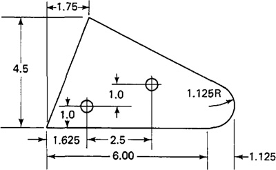
the workpart surfaces, to go to point locations, to drill holes at these locations, and so on. In addition to part geometry and tool motion statements, the programmer must also provide other instructions to operate the machine tool properly. We will consider the various categories of instructions for the APT language in Section 8.6.
The computer’s job
The computer’s job in computer-assisted part programming consists of the following steps:
1. Input translation
2. Arithmetic calculations
3. Cutter offset computation
4. Postprocessor
The sequence of these steps and their relationships to the part programmer and the machine tool are illustrated in Figure 8.7.
The part programmer enters the program written in the APT or other language. The input translation component converts the coded instructions contained in the program into computer-usable form, preparatory to further processing.
The arithmetic calculations unit of the system consists of a comprehensive set of subroutines for solving the mathematics required to generate the part surface. These subroutines are called by the various part programming language statements. The arithmetic unit is really the fundamental element in the part programming package. This unit frees the programmer from the time-consuming geometry and trigonometry calculations, to concentrate on the workpart processing.
Figure 8.7 Steps in computer-assisted part programming.
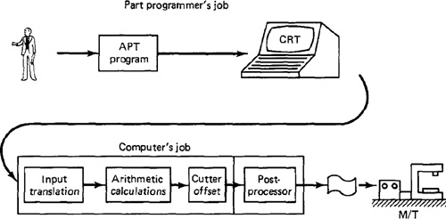
Figure 8.8 Cutter offset problem in part programming for contouring.

The second task of the part programmer is that of constructing the tool path. However, the actual tool path is different from the part outline because the tool path is defined as the path taken by the center of the cutter. It is at the periphery of the cutter that machining takes place. The purpose of the cutter offset computations is to offset the tool path from the desired part surface by the radius of the cutter. This means that the part programmer can define the exact part outline in the geometry statements. Thanks to the cutter offset calculation provided by the programming system, the programmer need not be concerned with this task. The cutter offset problem is illustrated in Figure 8.8.
As noted previously, NC machine tool systems are different. They have different features and capabilities. They use different NC tape formats. Nearly all of the part programming languages, including APT, are designed to be general-purpose languages, not limited to one or two machine tool types. Therefore, the final task of the computer in computer-assisted part programming is to take the general instructions and make them specific to a particular machine tool system. The unit that performs this task is called a postprocessor.
The postprocessor is a separate computer program that has been written to prepare the punched tape for a specific machine tool. The input to the postprocessor is the output from the other three components: a series of cutter locations and other instructions. The output of the postprocessor is the NC tape written in the correct format for the machine on which it is to be used.
NC part programming languages
An NC part programming language consists of a software package (computer program) plus the special rules, conventions, and vocabulary words for using that software. Its purpose is to make it convenient for a part programmer to communicate the necessary part geometry and tool motion information to the computer so that the desired part program can be prepared. The vocabulary words are typically mnemonic and English-like, to make the NC language easy to use.
There have probably been over 100 NC part programming languages developed since the initial MIT research on NC programming in the mid-1950s. Most of the languages were developed to meet particular needs and have not survived the test of time. Today, there are several dozen NC languages still in use. Refinements and enhancements to existing languages are continually being made. The following list provides a description of some of the important NC languages in current use.
APT (Automatically Programmed Tools). The APT language was the product of the MIT developmental work on NC programming systems. Its development began in June, 1956, and it was first used in production around 1959. Today it is the most widely used language in the United States. Although first intended as a contouring language, modern versions of APT can be used for both positioning and continuous-path programming in up to five axes. Versions of APT for particular processes include APTURN (for lathe operations), APTMIL (for milling and drilling operations), and APTPOINT (for point-to-point operations).
ADAPT (ADaptation of APT). Several part programming languages are based directly on the APT program. One of these is ADAPT, which was developed by IBM under Air Force contract. It was intended to provide many of the features of APT but to utilize a smaller computer. The full APT program requires a computing system that would have been considered large by the standards of the 1960s. This precluded its use by many small and medium-sized firms that did not have access to a large computer. ADAPT is not as powerful as APT, but it can be used to program for both positioning and contouring jobs.
EXAPT (Extended subset of APT). This was developed in Germany starting around 1964 and is based on the APT language. There are three versions: EXAPT I—designed for positioning (drilling and also straight-cut milling), EXAPT II—designed for turning, and EXAPT III—designed for limited contouring operations. One of the important features of EXAPT is that it attempts to compute optimum feeds and speeds automatically.
UNIAPT. The UNIAPT package represents another attempt to adapt the APT language to use on smaller computers. The name derives from the developer, the United Computing Corp. of Carson, California. Their efforts have provided a limited version of APT to be implemented on minicomputers, thus allowing many smaller shops to possess computer-assisted programming capacity.
SPLIT (Sundstrand Processing Language Internally Translated). This is a proprietary system intended for Sundstrand’s machine tools. It can handle up to five-axis positioning and possesses contouring capability as well. One of the unusual features of SPLIT is that the postprocessor is built into the program. Each machine tool uses its own SPLIT package, thus obviating the need for a special postprocessor.
COMPACT II. This is a package available from Manufacturing Data Systems, Inc. (MDSI), a firm based in Ann Arbor, Michigan. The NC language is similar to SPLIT in many of its features. MDSI leases the COMPACT II system to its users on a time-sharing basis. The part programmer uses a remote terminal to feed the program into one of the MDSI computers, which in turn produces the NC tape. The COMPACT II language is one of the most widely used programming languages. MDSI has roughly 3000 client companies which use this system.
PROMPT. This is an interactive part programming language offered by Weber N/C System, Inc., of Milwaukee, Wisconsin. It is designed for use with a variety of machine tools, including lathes, machining centers, flame cutters, and punch presses.
CINTURNII. This is a high-level language developed by Cincinnati Milacron to facilitate programming of turning operations.
The most widely used NC part programming language is APT, including its derivatives (ADAPT, EXAPT, UNIAPT, etc.). We present the basic elements of the APT language in Section 8.6.
Time-sharing versus in-house computer
There are two ways to implement a computer-assisted part programming system. The first is by means of a time-sharing service and the second is by means of a computer at the company’s own plant.
Time-sharing services provide a relatively low cost means for a company to get started in computer-assisted NC part programming. The company accesses the NC language of the service over telephone lines. Several of the NC languages listed previously are available primarily through time-sharing service companies (COMPACT II and PROMPT are good examples). The cost advantage to the client company is that the billing is based on the use of the service. There is no large fixed cost required to purchase a lot of hardware. The remote terminal and the tape punching equipment are basically all that the company needs in order to use the time-sharing service. The billing for the service includes such items as CPU time (actual time spent using the computer’s central processing unit)-, terminal-connect time, data storage, and so forth. There is also the telephone bill.
In the growth of NC within a particular plant, the company eventually reaches a point at which the cost of using the time-sharing service becomes very high. This point varies for different companies, but when the plant is paying monthly bills of several thousand dollars for the time-sharing service, it should probably begin to consider its own in-house programming system. This is accomplished either by purchasing a dedicated computer which will be used exclusively for NC part programming, or by loading one or more NC language packages on the company’s existing data processing facilities. The cost of installing an in-house capability can be considerable, but if the volume of part programming work is high, the overall cost is lower than the cost of time sharing. Many companies have installed their own computer capability, but have also continued to retain timesharing services for maximum flexibility.
8.6 The Apt Language
In this section we present an introduction to the APT language for computer-assisted part programming. Our objectives are to demonstrate the English-like statements of this NC language and to show how they are used to command the cutting tool through its sequence of machining operations.
APT is not only an NC language; it is also the computer program that performs the calculations to generate cutter positions based on APT statements. We will not consider the internal workings of the computer program. Instead, we will concentrate on the language that the part programmmer must use.
APT is a three-dimensional system that can be used to control up to five axes. We will limit our discussion to the more familiar three axes, x, y, and z, and exclude rotational coordinates. APT can be used to control a variety of different machining operations. We will cover only drilling and milling applications. There are over 400 words in the APT vocabulary. Only a small (but important) fraction will be covered here.
There are four types of statements in the APT language:
1. Geometry statements. These define the geometric elements that comprise the workpart. They are also sometimes called definition statements.
2. Motion statements. These are used to describe the path taken by the cutting tool.
3. Postprocessor statements. These apply to the specific machine tool and control system. They are used to specify feeds and speeds and to actuate other features of the machine.
4. Auxiliary statements. These are miscellaneous statements used to identify the part, tool, tolerances, and so on.
Geometry statements
To program in APT, the workpart geometry must first be defined. The tool is subsequently directed to move to the various point locations and along surfaces of the workpart which have been defined by these geometry statements. The definition of the workpart elements must precede the motion statements.
The general form of an APT geometry statement is this:
symbol = geometry type/descriptive data (8.1)
An example of such a statement is
PI = POINT/5.0, 4.0, 0.0 (8.2)
The statement is made up of three sections. The first is the symbol used to identify the geometric element. A symbol can be any combination of six or fewer alphabetic and numeric characters. At least one of the six must be an alphabetic character. Also, although it may seem obvious, the symbol cannot be one of the APT vocabulary words.
The second section of the geometry statement is an APT vocabulary word that identifies the type of geometry element. Besides POINT, other geometry elements in the APT vocabulary include LINE, PLANE, and CIRCLE.
The third section of the geometry statement comprises the descriptive data that define the element precisely, completely, and uniquely. These data may include quantitative dimensional and positional data, previously defined geometry elements, and other APT words.
The punctuation used in the APT geometry statement is illustrated in the example, Eq. (8.2). The statement is written as an equation, the symbol being equated to the surface type. A slash separates the surface type from the descriptive data. Commas are used to separate the words and numbers in the descriptive data.
There are a variety of ways to specify the different geometry elements. The appendix at the end of this chapter presents a dictionary of APT vocabulary words as well as a sampling of statements for defining the geometry elements we will be using: points, lines, circles, and planes. The reader may benefit from a few examples.
To specify a line, the easiest method is by two points through which the line passes:
L3 = LINE/P3, P4
The part programmer may find it convenient to define a new line parallel to another line which has previously been defined. One way of doing this would be
L4 = LINE/P5, PARLEL, L3
This states that the line L4 must pass through point P5 and be parallel (PARLEL) to line L3.
A plane can be defined by specifying three points through which it passes:
PL1 = PLANE/P1, P4, P5
Of course, the three points must not lie along a straight line. A plane can also be defined as being parallel to another plane, similar to the previous line parallelism statement.
Plane PL2 is parallel to plane PL1 and passes through point P2.
A circle can be specified by its center and its radius.
C1 = CIRCLE/CENTER, PI, RADIUS, 5.0
The two APT descriptive words are used to identify the center and radius. The orientation of the circle perhaps seems undefined. By convention, it is a circle located in the x-y plane.
There are several ground rules that must be followed in formulating an APT geometry statement:
1. The coordinate data must be specified in the order x, y, z. For example, the statement
PI = POINT/5.0, 4.0, 0.0
is interpreted by the APT program to mean a point x = 5.0, y = 4.0, and z = 0.0.
2. Any symbols used as descriptive data must have been previously defined. For example, in the statement
P2 = POINT/INTOF, L1, L2
the two lines L1 and L2 must have been previously defined. In setting up the list of geometry statements, the APT programmer must be sure to define symbols before using them in subsequent statements.
3. A symbol can be used to define only one geometry element. The same symbol cannot be used to define two different elements. For example, the following sequence would be incorrect:
P1 = POINT/1.0, 1.0, 1.0
P1 = POINT/2.0, 3.0, 4.0
4. Only one symbol can be used to define any given element. For example, the following two statements in the same program would render the program incorrect:
P1 = POINT/1.0, 1.0, 1.0
P2 = POINT/1.0, 1.0, 1.0
5. Lines defined in APT are considered to be of infinite length in both directions. Similarly, planes extend indefinitely and circles defined in APT are complete circles.
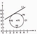
Figure 8.9 Workpart from Figure 8.6 redrawn with x-y coordinate system and geometric elements labeled.

Example 8.2
To illustrate some of these geometry statements we will define the geometry of the workpart shown in Figure 8.6. The drawing of the part is duplicated in Figure 8.9, except that we have added the coordinate axis system and labeled the various geometric elements. We also add the target point P0 to be used in subsequent motion commands.
PO = POINT/0,-1.0,0
P1 = POINT/6.0, 1.125,0
P2 = POENT/0, 0, 0
P3 = POINT/6.0, 0, 0
P4 = POINT/1.75,4.5,0
L1 = LINE/P2, P3
C1 = CIRCLE/CENTER, PI, RADIUS, 1.125
L2 = LINE/P4, LEFT, TANTO, Cl
L3 = LINE/P2, P4
PL1 = PLANE/P2, P3, P4
Motion statements
APT motion statements have a general format, just as the geometry statements do. The general form of a motion statement is
motion command/descriptive data (8.3)
An example of a motion statement is
GOTO/P1 (8.4)
The statement consists of two sections separated by a slash. The first section is the basic motion command, which tells the tool what to do. The second section is comprised of descriptive data, which tell the tool where to go. In the example statement above, the tool is commanded to go to point P1, which has been defined in a preceding geometry statement.
At the beginning of the motion statements, the tool must be given a starting point. This point is likely to be the target point, the location where the operator has positioned the tool at the start of the job. The part programmer keys into this starting position with the following statement:
FROM/TARG (8.5)
The FROM is an APT vocabulary word which indicates that this is the initial point from which others will be referenced. In the statement above, TARG is the symbol given to the starting point. Any other APT symbol could be used to define the target point. Another way to make this statement is
FROM/-2.0, -2.0, 0.0
where the descriptive data in this case are the x, y, and z coordinates of the target point. The FROM statement occurs only at the start of the motion sequence.
It is convenient to distinguish between PTP movements and contouring movements when discussing the APT motion statements.
POINT-TO-POINT MOTIONS. There are only two basic PTP motion commands: GOTO and GODLTA. The GOTO statement instructs the tool to go to a particular point location specified in the descriptive data. Two examples would be:
GOTO/P2
GOTO/2.0, 7.0, 0.0
In the first statement, P2 is the destination of the tool point. In the second statement, the tool has been instructed to go to the location whose coordinates are x = 2.0, y = 7.0, and z = 0.
The GODLTA command specifies an incremental move for the tool. For example, the statement
GODLTA/2.0, 7.0, 0.0
instructs the tool to move from its present position 2 in. in the x direction and 7 in. in the y direction. The z coordinate remains unchanged.
The GODLTA command is useful in drilling and related operations. The tool can be directed to a particular hole location with the GOTO statement. Then the GODLTA command would be used to drill the hole, as in the following sequence:
GODLTA/0,0, -1.5
GODLTA/0,0,+1.5
Example 8.3
Example 8.1 was a PTP job which was programmed manually. Let us write the APT geometry and motion statements necessary to perform the drilling portion of this job. We will set the plane defined by z = 0 about ¼ in. above the part surface. The part will be assumed to be ½ in. thick. The reader should refer back to Figures 8.3 and 8.4.
P1 = POINT/1.0, 2.0,0
P2 = POINT/1.0, 1.0,0
P3 = POINT/3.5, 1.5,0
P0 = POINT/-1.0, 3.0, 2.0
FROM/PO
GOTO/P1
GODLTA/0,0,-1.0
GODLTA/0,0,+1.0
GOTO/P2
GODLTA/0,0, -1.0
GODLTA/0,0, +1.0
GOTO/P3
GODLTA/0,0,-1.0
GODLTA/0,0,+1.0
GOTO/PO
This is not a complete APT program because it does not contain the necessary auxiliary and postprocessor statements. However, the statement sequence demonstrates how geometry and motion statements can be combined to command the tool through a series of machining steps.
CONTOURING MOTIONS. Contouring commands are somewhat more complicated because the tool’s position must be continuously controlled throughout the move. To accomplish this control, the tool is directed along two intersecting surfaces as shown in Figure 8.10. These surfaces have very specific names in APT:
1. Drive surface. This is the surface (it is pictured as a plane in Figure 8.10) that guides the side of the cutter.
2. Part surface. This is the surface (again shown as a plane in the figure) on which the bottom of the cutter rides. The reader should note that the “part surface” may or may not be an actual surface of the workpart. The part programmer must define this plus the drive surface for the purpose of maintaining continuous path control of the tool.
There is one additional surface that must be defined for APT contouring motions:
Figure 8.10 Three surfaces in APT contouring motions which guide the cutting tool.

3. Check surface. This is the surface that stops the movement of the tool in its current direction. In a sense, it checks the forward movement of the tool.
There are several ways in which the check surface can be used. This is determined by APT modifier words within the descriptive data of the motion statement. The three main modifier words are TO, ON, and PAST, and their use with regard to the check surface is shown in Figure 8.11. A fourth modifier word is TANTO. This is used when the drive surface is tangent to a circular check surface, as illustrated in Figure 8.12. In this case the cutter can be brought to the point of tangency with the circle by use of the TANTO modifier word.
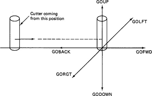
The APT contour motion statement commands the cutter to move along the drive and part surfaces and the movement ends when the tool is at the check surface. There are six motion command words:
GOLFT GOFWD GOUP
GORGT GOBACK GODOWN
Figure 8.11 Use of APT modifier words in a motion statement: TO, ON and PAST. TO moves tool into initial contact with check surface. ON moves tool until tool center is on check surface. PAST moves tool just beyond check surface.

Figure 8.12 Use of APT modifier word TANTO. TANTO moves tool to point of tangency between two surfaces, at least one of which is circular.

Their interpretation is illustrated in Figure 8.13. In commanding the cutter, the programmer must keep in mind where it is coming from. As the tool reaches the new check surface, does the next movement involve a right turn or an upward turn or what? The tool is directed accordingly by one of the six motion words. In the use of these words, it is helpful for the programmer to assume the viewpoint that the workpiece remains stationary and the tool is instructed to move relative to the piece. To begin the sequence of motion commands, the FROM statement, Eq. (8.5) is used in the same manner as for PTP moves. The statement following the FROM statement defines the initial drive surface, part surface, and check surface. The sequence is of the following form:
FROM/TARG
GO/TO, PL1, TO, PL2, TO, PL3
The symbol TARG represents the target point where the operator has set up the tool. The GO command instructs the tool to move to the intersection of the drive
Figure 8.13 Use of APT motion commands.
surface (PL1), the part surface (PL2), and the check surface (PL3). The periphery of the cutter is tangent to PL1 and PL3, and the bottom of the cutter is touching PL2. This cutter location is defined by use of the modifier word TO. The three surfaces included in the GO statement must be specified in the order: drive surface first, part surface second, and check surface last.
Note that the GO/TO command is different from the GOTO command. GOTO is used only for PTP motions. GO/TO is used to initialize the sequence of contouring motions.
After initialization, the tool is directed along its path by one of the six command words. It is not necessary to repeat the symbol of the part surface after it has been defined. For instance, consider Figure 8.14. The cutter has been directed from TARG to the intersection of surfaces PL1, PL2, and PL3. It is desired to move the tool along plane PL3. The following command would be used:
GORGT/PL3, PAST, PL4
This would direct the tool to move along PL3, using it as the drive surface. The tool would continue until past surface PL4, which is the new check surface. Although the part surface (PL2) may remain the same throughout the motion sequence, the drive surface and check surface are redefined in each new command.
Let us consider an alternative statement to the above which would accomplish the same motion but would lead to easier programming:
GORGT/L3, PAST, L4
We have substituted lines L3 and L4 for planes PL3 and PL4, respectively. When looking at a part drawing, such as Figure 8.6, the sides of the part appear as lines. On the actual part, they are three-dimensional surfaces, of course. However, it would be more convenient for the part programmer to define these surfaces as lines and circles rather than planes and cylinders. Fortunately, the APT computer program allows the geometry of the part to be defined in this way. Hence the lines L3 and L4 in the foregoing motion statement are treated as the drive surface and check surface. This substitution can only be made when the part surfaces are perpendicular to the x-y plane.
Figure 8.14 Initialization of APT contouring motion sequence.

Example 8.4
To demonstrate the use of the motion commands in a contouring sequence, we will refer back to the workpart of Example 8.2. The geometry statements were listed in this example for the part shown in Figure 8.9. Using the geometric elements shown in this figure, following is the list of motion statements to machine around the periphery of the part. The sequence begins with tool located at the target point PO.
FROM/PO
GO/TO,LI,TO,PL1,TO,L3
GORGT/L1,TANTO,Cl
GOFWD/C1,PAST, L2
GOFWD/L2, PAST, L3
GOLFT/L3, PAST, LI
GOTO/PO
The reader may have questioned the location of the part surface (PL1) in the APT sequence. For this machining job, the part surface must be defined below the bottom plane of the workpiece in order for the cutter to machine the entire thickness of the piece. Therefore, the part surface is really not a surface of the part at all.
Example 8.4 raises several other questions: How is the cutter size accounted for in the APT program? How are feeds and speeds specified? These and other questions are answered by the postprocessor and auxiliary statements.
Postprocessor statements
To write a complete part program, statements must be written that control the operation of the spindle, the feed, and other features of the machine tool. These are called postprocessor statements. Some of the common postprocessor statements that appear in the appendix at the end of the chapter are:
COOLNT/ RAPID
END SPINDL/
FEDRAT/ TURRET/
MACHlN/
The postprocessor statements, and the auxiliary statements in the following section, are of two forms: either with or without the slash (/). The statements without the slash are self-contained. No additional data are needed. The APT words with the slash require descriptive data after the slash. These descriptions are given for each word in the appendix.
The FEDRAT/ statement should be explained. FEDRAT stands for feed rate and the interpretation of feed differs for different machining operations. In a drilling operation the feed is in the direction of the drill bit axis. However, in an end milling operation, typical for NC, the feed would be in a direction perpendicular to the axis of the cutter.
Auxiliary statements
The complete APT program must also contain various other statements, called auxiliary statements. These are used for cutter size definition, part identification, and so on. The following APT words used in auxiliary statements are defined in the appendix to this chapter:
CLPRNT INTOL/
CUTTER OUTTOL/
FINI PARTNO
The offset calculation of the tool path from the part outline is based on the CUTTER/definition. For example, the statement
CUTTER/.500
would instruct the APT program that the cutter diameter is 0.500 in. Therefore, the tool path must be offset from the part outline by 0.250 in.
Example 8.5
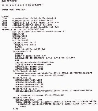
We are now in a position to write a complete APT program. The workpart of Example 8.4 will be used to illustrate the format of the APT program.
We will assume that the workpiece is a low-carbon steel plate, which has previously been cut out in the rough shape of the part outline. The tool is a ½-in.-diameter end-milling cutter. Typical cutting conditions might be recommended as follows: cutting speed = 573 rpm and feed = 2.29in./min.
Figure 8.15 presents the program with correct character spacing identified at the top as if it were to be keypunched onto computer cards. Modern NC programming systems utilize a CRT terminal for program entry.
8.7 The Macro Statement in Apt
In the preceding section we described the basic ingredients of the APT language. In the present section we describe a very powerful feature of APT, the MACRO statement. The MACRO feature is similar to a subroutine in FORTRAN and other computer programming languages. It would be used where certain motion sequences would be repeated several times within a program. The purpose in using a MACRO subroutine is to reduce the total number of statements required in the APT program, thus making the job of the part programmer easier and less time
Figure 8.15 APT program for Example 8.5.

consuming. The MACRO subroutine is defined by a statement of the following format:
symbol = MACRO/parameter definition(s) (8.6)
The rules for naming the MACRO symbol are the same as for any other APT symbol. It must be six characters or fewer and at least one of the characters must be a letter of the alphabet. The parameter definition(s) following the slash would identify certain variables in the subroutines which might change each time the subroutine was called into use. Equation (8.6) would serve as the title and first line of a MACRO subroutine. It would be followed by the set of APT statements that comprise the subroutine. The very last statement in the set must be the APT word TERMAC. This signifies the termination of the MACRO.
To activate the MACRO subroutine within an APT program, the following call statement would be used:
CALL/symbol, parameter specification (8-7)
The symbol would be the name of the MACRO that is to be called. The parameter specification identifies the particular values of the parameters that are to be used in this execution of the MACRO subroutines.
An example will serve to illustrate the use of the MACRO statement and how the MACRO would be called by the main APT program.
Example 8.6
We will refer back to the drilling operations of Example 8.2. In this example the GODLTA sequence was repeated in the program a total of three times, once for each hole. This represents an opportunity to use the MACRO feature in the APT system. The four point locations (PO, P1, P2, and P3) would be defined just as they are in Example 8.2. These points would be used in the MACRO subroutine and main APT program in the following way:
DRILL = MACRO/PX
GOTO/PX
GODLTA/0, 0,-1.0
GODLTA/0,0,+1.0
TERMAC
FROM/PO
CALL/DRILL, PX = P1
CALL/DRILL, PX = P2
CALL/DRILL, PX = P3
GOTO/PO
In this example the number of APT motion statements in the main program has been reduced from 11 down to five. (If we include the MACRO subroutine in our line count, the reduction is from 11 statements to 10.) The reader can visualize the power of the MACRO feature for a programming job in which there are a large number of holes to be drilled. The savings in the required number of APT statements would approach 662/3% in this case, since one call statement replaces three motion statements in the program.
The MACRO feature has many uses in APT. They are limited primarily by the imagination of the part programmer. Some of these uses will be considered in the exercise problems at the end of the chapter. It is even possible to have a CALL/ statement within one MACRO which refers to another MACRO subroutine. This might be used for example in a matrix of holes where both the x and y positions of the holes are changed with each drilling operation.
Another common use of the MACRO feature would be for a roughing and finishing sequence on a given workpart. This is conveniently handled by defining the motion sequence in the MACRO, and calling the MACRO twice with two different cutter diameters. The CALL for the roughing cut would specify a larger cutter diameter than the CALL for the finishing cut, even though the actual cutter is the same for both operations. An example will illustrate this powerful use of the MACRO feature.
Example 8.7
In this example we perform a roughing cut and a finishing cut on the workpart of Example 8.5. It is a milling sequence in which the same 0.50-in.-diameter end-milling cutter will be used to rough and finish the part outline. The roughing operation will be performed so that 0.035 in. of material is remaining on the part for the finishing cut. The finishing operation will then cut the part to final size.
The only difference between the roughing sequence and the finishing sequence is that the tool offset is greater for the roughing cut. Therefore, the motion sequence can be defined in a MACRO and the tool offset can be defined by changing the diameter specification each time the MACRO is called. This would be done in the following way.
MILL = MACRO/DIA
CUTTER/DIA
FROM/PO
GO/TO, L1, TO, PL1, TO, L3
GORGT/Ll.TANTO,Cl
GOFWD/C1,PAST, L2
GOFWD/L2, PAST, L3
GOLFT/L3, PAST, LI
GOTO/PO
The main part of the program which refers to this MACRO would simply consist of
CALL/MILL, DIA = .570
CALL/MILL, DIA = .500
The first statement accomplishes the roughing operation with the cutter path offset from the desired part outline by one-half of the stated diameter. This leaves 0.035 in. to be machined by the cutter during the finishing pass. It might be desirable to reduce the feedrate for the finishing pass to achieve a better surface.
The MACRO feature is only one of the many features in APT. We have only scratched the surface in this powerful part programming system. However, enough of the APT language has been included to permit the reader to try some of the programming exercises at the end of the chapter.
8.8 NC Programming with Interactive Graphics
There are several innovations in NC part programming which have developed during the middle and late 1970s. Their use is expected to grow substantially during the 1980s. The first involves the use of interactive graphics as a highly productive aid in performing the part programming process. We cover this topic in the present section. The second innovation is voice programming. This involves the input of NC programming statements through oral communication by the human programmer. Voice programming is described in Section 8.9. The third development during the past few years is manual data input (MDI) of the NC part program. In a sense, this involves a step backward in NC programming technology. We explain why in Section 8.10.
The use of interactive graphics in NC part programming is an excellent example of the integration of computer-aided design and computer-aided manufacturing. The programming procedure is carried out on the graphics terminal of a CAD/CAM system. Using the same geometric data which defined the part during the computer-aided design process, the programmer constructs the tool path using high-level commands to the system. In many cases the tool path is automatically generated by the software of the CAD/CAM system. The output resulting from the procedure is a listing of the APT program or the actual CLFILE (cutter location file) which can be postprocessed to generate the NC punched tape.
Let us consider the step-by-step procedure that would be used to generate the NC part program using a CAD/CAM system. We will then illustrate the procedure with an example. All of the major CAD/CAM system vendors offer part programming packages. Although the features of these packages vary between the vendors, they all operate in a similar way. In our description of the procedure we will attempt to portray a composite of the various packages.
Initial steps in the procedure
The CAD/CAM procedure for NC programming begins with the geometric definition of the part. A significant benefit of using a CAD/CAM system is realized when these geometry data have already been created during design. If the geometric model of the part has not been previously created, it must be constructed on the graphics terminal.
With the part displayed on the CRT screen, the programmer would proceed to label the various surfaces and elements of the geometry. The CAD/CAM system would accomplish the labeling in response to a few simple commands by the programmer. After labeling is completed, the APT geometry statements can be generated automatically by the system.
In addition to the ease with which the APT geometry has been defined using the CAD/CAM system, there are several other benefits afforded the user of a graphics system for NC part programming. The part can be displayed at various angles, magnifications, and cross sections to examine potential problem areas in machining. This capability to manipulate the part image on the CRT screen is helpful to the programmer in visualizing the design of the part. Also, with the part defined in the computer, the programmer can overlay the outline of the raw work-part to consider the number of passes required to complete the machining. Alternative methods of fixturing the part can be explored using the graphics terminal.
Tool selection is the next step in the procedure. The CAD/CAM system would typically have a tool library with the various tools used in the shop catalogued according to the type. The programmer could either select one of these tools or create a new tool design by specifying the parameters and dimensions of the new tool (diameter, corner radius, cutter length, etc.).
Generation of the tool path
At this point in the procedure, the programmer has a geometric model of the work-part and the tools needed to machine the part. The next step is to create the cutter path. The method of accomplishing this using interactive graphics depends on the type of operation (e.g., profile milling, turning, sheet metal working) and the complexity of the part. The currently available commercial CAD/CAM systems use an interactive approach, with certain common machining routines being done automatically by the system. These automatic routines might include profile milling around a part outline, end milling a pocket, point-to-point, PTP presswork hole piercing, and surface contouring.
The interactive approach permits the programmer to generate the tool path in a step-by-step manner with visual verification on the graphics display. The procedure begins by defining a starting position for the cutter. The programmer would then command the tool to move along the defined geometric surfaces of the part. As the tool is being moved on the CRT screen, the corresponding APT motion commands are automatically prepared by the CAD/CAM system. The interactive mode provides the user with the opportunity to insert postprocessor statements at appropriate points during program creation. These postprocessor statements would consist of machine tool instructions such as feed rates, speeds, and control of the cutting fluid.
The automatic machining routines are called into operation for frequently encountered part programming situations. These routines are analogous to high-level MACRO subroutines which have been developed as part of the CAD/CAM system software. The part geometry data represent the set of parameter definitions or arguments for the MACRO. Accordingly, these automatic routines can be called with a minimum of user interaction.
Profiling and pocketing are two common examples of automatic machining routines that are available on most CAD/CAM systems. The profiling routine is used to generate the sequence of cutter paths for machining around a series of geometry elements which have been identified by the user. These geometry elements would typically define the outline of the workpart. Let us consider an example to illustrate the graphics approach to NC programming and the automatic profiling feature in particular.
Example 8.8
In this example we generate the APT program and CLFILE for the part from our previous Example 8.5. The Applicon CAD/CAM system in the Computer-Aided Manufacturing Lab at Lehigh University was used to accomplish the programming using Applicon’s AGS/883 package. Since part programming is performed on a graphics terminal of the CAD/CAM system, the example will be developed by means of figures generated by the system. Figure 8.16 shows the part geometry as created on the Applicon terminal. Labeling of the geometry elements is accomplished automatically by the system under prompting by the user. Figure 8.17 shows the part with labeling added. The machining in this example involves profile milling around the circumference of the part. The Applicon system has an automatic routine for generating the tool path for this situation. The lines representing the cutter path are pictured in Figure 8.18. Figure 8.19 shows the APT program listing as generated on the CAD/CAM system. Note that the list of statements is not identical to those developed in Example 8.5.
Figure 8.16 Part from Figure 8.6 redrawn on the Applicon CAD/CAM system.

Figure 8.17 Workpart with labels added by Applicon CAD/CAM system.

Figure 8.18 Cutter path generated automatically by application CAD/CAM system.

Figure 8.19 APT program listing as generated by Applicon CAD/CAM system.
The automatic pocketing routine works in a manner similar to the profiling routine except that the part material is removed from within a closed set of boundary elements. These elements define a pocket or cavity in the workpart which needs to be machined out. The programmer would have to identify the sides and bottom of the pocket. The system would then generate the tool path to machine the pocket. This feature is illustrated in Figure 8.20.
In generating the tool path on a CAD/CAM system the use of color graphics is very helpful to the programmer. The part can be displayed in one color, while the tool path would be shown in a different color. This permits easy visual differentiation of the tool path from the part outline. Another feature which aids visualization of the machining sequence is dynamic tool path simulation on the graphics screen. An example of this feature is Computervision’s 3D Dynamic Verification of NC Toolpaths. As illustrated in Figure 8.21, the orientation of the tool and toolholder can be shown on the screen relative to the workpiece. The simulated tool motion can be displayed in any of several modes: (1) high-speed motion, which reduces the time to verify the tool path; (2) actual speed, which shows the tool feed at the commanded rate; (3) freeze mode, which stops the tool motion for close inspection; and (4) stepping mode, which displays the tool path in discrete steps.
Advantages of CAD/CAM in NC programming
The CAD/CAM approach offers several very significant advantages in numerical control part programming. Among these advantages are the following:
Figure 8.20 Automatic pocketing routing generated on Computervision. (Courtesy of Computervision Corp.)

Figure 8.21 Dynamic verification of NC tool path in three-dimensional view. (Courtesy of Computervision Corp.)

1. Savings in geometry definition. Since the part geometry data have already been created during design using the CAD/CAM graphics system, the part programmer is not required to redefine the geometry of the part. This can be a time-consuming procedure in conventional APT programming.
2. Immediate visual verification. The graphics terminal provides a display of the tool path for immediate verification by the part programmer. Most programming errors can be detected by the user and corrected at the time the error is made. With conventional APT or other NC language, there is a delay between writing the program and the verification/correction process.
3. Use of automatic programming routines. For common part programming situations such as profiling and pocketing, the use of automatic MACRO-type routines yields a significant reduction in part programming time.
4. One-of-a-kind jobs. Because the part programming time is significantly reduced when using a CAD/CAM system, numerical control becomes an economically attractive method for producing one-of-a-kind jobs. Without CAD/CAM, the time required to prepare the part program represents a significant obstacle which often precludes the use of NC for one/off production.
5. Integration with other related functions. There is the obvious opportunity to integrate the product design function with part programming. Other opportunities for functional integration within manufacturing also exist. These include tool design, process planning, preparation of operator and setup instructions, grouping of parts into families for programming convenience, and so on. With the tremendous advances made in NC programming over the last three decades, it is not difficult to imagine that the entire logic of the part programming process will be captured and put on the computer. This would permit NC programming to be accomplished completely and automatically by the computer without human assistance.
8.9 Voice NC Programming
Voice programming of NC machines (abbreviated VNC) involves vocal communication of the machining procedure to a voice-input NC tape-preparation system. VNC allows the programmer to avoid steps such as writing the program by hand, keypunching or typing, and manual verification. One of the principal companies specializing in voice-input systems is Threshold Technology, Inc., of Delran, New Jersey.
To perform the part programming process with VNC, the operator speaks into a headband microphone designed to reduce background acoustical noise. Communication of the programming instructions is in shop language with such terms as “turn,” “thread,” and “mill line,” together with numbers to provide dimensional and coordinate data. Before the voice-input system can be used, it must be “trained” to recognize and accept the individual programmer’s voice pattern. This is accomplished by repeating each word of the vocabulary about five times to provide a reference set which can subsequently be compared to voice commands given during actual programming. The entire vocabulary for the Threshold system contains about 100 words. Most NC programming jobs can be completed by using about 30 of these vocabulary words.
In talking to the system, the programmer must isolate each word by pausing before and after the word. The pause must be only one-tenth of a second or longer. This allows the speech recognition system to identify boundaries for the uttered command so that its wave characteristics can be compared with words in the reference set for that programmer. Typical word input rates under this restriction are claimed to be about 70 per minute. As the words are spoken, a CRT terminal in front of the operator verifies each command and prompts the operator for the next command.
Example 8.9
A typical dialogue between the VNC system (printing on the CRT screen) and the programmer (speaking) might go as follows for defining a circle:
Programmer: “Define”
System: DEFINITION TYPE
Programmer: “Circle”
System: CIRCLE # =
Programmer: “Three”
System: CENTER PT X =
Programmer: “Five decimal three one, Go”
System: Y =
Programmer: “Two decimal four seven five, Go”
System: RADIUS =
Programmer: “One decimal five, Go”
System: CW/CCW
Programmer: “Counterclockwise”
When all of the programming instructions have been entered and verified, the system prepares the punched tape for the job.
The advantages of VNC lie principally in the savings in programming time and resulting improvements in manufacturing lead time. Savings in programming time up to 50% are claimed. Improvements in accuracy and lower computer-skill requirements for the programmer are also given as benefits of VNC.
8.10 Manual Data Input
Manual data input (MDI) involves the entry of part programming data through a CRT display at the machine site; hence the use of punched tape is avoided. The programming process is usually carried out by the machine operator. NC systems equipped with MDI capability possess a computer (microcomputer) as the control unit.
MDI systems are designed to facilitate the part programming process by using an interactive mode to assist the operator through the programming steps. It queries the operator about the details of the machining job so that the operator types in the program responding to the sequence of questions. MDI units use shop language rather than alphanumeric codes. This removes some of the mystery usually surrounding the programming activity. Basically, the operator must be able to read an engineering drawing and be familiar with the machining process. No extensive training is required in NC part programming.
The great advantage of MDI is its simplicity. It represents a relatively easy way for a small shop to make the transition to numerical control. There is a minimum of change in normal shop procedures needed to use NC systems featuring manual data input. Since no punched tape is employed with MDI, the shop is spared the expense of tape punching equipment normally associated with NC.
The limitation on MDI is that the programs should be relatively short and simple. This means that the machining jobs should be uncomplicated. There are several reasons for this limitation. First, since there is no paper copy of the program, there is a limit on the length and complexity of program that the operator is capable of visualizing. Also, the CRT can only display a total of 22 or 25 lines, so this adds to the operator’s visualization problem. Finally, one of the biggest disadvantages of manual data input is that the machine tool itself is not productive while programming is being accomplished. In essence, a very expensive piece of equipment is being utilized to prepare the part program. The more complicated the program, the more time is taken when the machine is not cutting metal.
One way of overcoming this last disadvantage, which is beginning to be offered on MDI machines, is for the machine to be operated in a foreground/ background mode. This allows the operator to be entering the next program into the system while the last part is still being produced from the program currently in computer memory. This foreground/background capability reduces the changeover time between jobs.
The particular features of MDI make it appropriate for workparts which are simpler than the usual NC jobs, and small batch sizes which are not likely to be repeated. On this issue of repeated batches, many MDI systems possess the optional feature in which programs can be extracted from computer memory for long-term storage (in anticipation of a repeat order). However, instead of using punched tape as the storage medium so typical in NC, magnetic tape cassettes, are the general storage device. The tape cassette can be stored in a part program library and then used to reenter the program into the MDI system’s control memory when needed.
References
[1] APPLICON, INC., AGS/883 NC II User’s Manual, Document A-20805, Burlington, Mass., 1981.
[2] CHILDS, J. J., Numerical Control Part Programming, Industrial Press, Inc., New York, 1973.
[3] COMPUTERVISION CORP., CADDS 4, Numerical Control Application Package, Publication PS-S47-01, Beford, Mass.
[4] GRINDSTAFF, C. C, “Computer Graphics for CAM Applications,” Commline, July/August, 1981, pp. 12–14.
[5] GROOVER, M. P., Automation, Production Systems, and Computer-Aided Manufacturing, Prentice-Hall, Inc., Englewood Cliffs NJ., 1980, Chapter 8.
[6] HATSCHEK, R. L., “NC Programming,” Special Report 719, American Machinist, February, 1980, pp. 119–134.
[7] HEGLAND, D. E., “Numerical Control—Your Best Investment in Productivity,” Production Engineering, March, 1981, pp. 42–47.
[8] HUBER, R. F., “Tell It to Your Machines,” Production, June, 1980.
[9] ILLINOIS INSTITUTE OF TECHNOLOGY RESEARCH INSTITUTE (IITRI), APT Part Programming, McGraw-Hill Book Company, New York, 1967.
[10] LERRO, J. P., “CAD/CAM System: More than an Automated Drafting Tool,” Design News, November 17, 1980.
[11] MACHOVER, C., AND BLAUTH, R. E. (Eds.), The CAD/CAM Handbook, Computervision Corp., Bedford, Mass., 1980.
[12] MARTIN, J. M., “Voice Commands Produce NC Tapes,” American Machinist, June, 1980, pp. 102–104.
[13] NEIL, R., “CAD/CAM Use in Numerical Control,” Proceedings, Eighteenth Annual Meeting and Technical Conference, Numerical Control Society, Dallas, Tex., May, 1981, pp. 56–82.
[14] ROBERTS, A. D., AND PRENTICE, R. C, Programming for Numerical Control Machines, 2nd ed., McGraw-Hill Book Company, New York, 1978.
[15] SCHAFFER, G., “Computer Graphics Goes to Work,” Special Report 724, American Machinist, July, 1980, pp. 149–164.
[16] THRESHOLD TECHNOLOGY, INC., “Programming Your N/C Machine Tools with Your Own Voice,” Delran, N.J.
[17] ZWICA, T., “MDI—The Pros and Cons,” Commline, September/October, 1980, pp.
Problems
8.1. The workpart of Figure P8.1 is to be completed in an NC drill press. The outline of the part has already been completed and the five holes are to be drilled. The axis system for this sequence is to be located with the origin at the lower left-hand corner of the part. The part is 3/8 in. thick.
(a) Write the APT geometry statements to define the hole locations.
(b) Write the sequence of motion statements in APT to perform the drilling sequence. Use a point at x = -1 and y = -3 as the target point for the FROM statement.
8.2. Write the complete APT program for the problem of Figure P8.1. The postprocessor call statement is MACHIN/DRILL. The drill size is 3/8-in. diameter and the work material is machinable aluminum. Cutting speed and feed rate are 900 revolutions per minute and 3.0 in./ min.
8.3. A profile milling operation is to be performed to generate the outline of the part in Figure P8.3. Disregard the two holes in the part. They have already been drilled and will be used to clamp the part to the machine table. The part is 1/2 in. thick.
Figure P8.1

Figure P8.3

(a) Write the APT geometry statements to define the part outline.
(b) Write the sequence of APT motion statements to perform the profile milling around the periphery of the part. Use a location 3 in. below and 3 in. to the left of the lower left-hand corner of the part as the target point for the FROM statement. Assume that the part has been cut to rough size with a bandsaw. This has left about 1/8 in. of material to be cut in the final profiling pass.
8.4. Write the complete APT program for the part of Problem 8.3. The postprocessor call statement is MACHIN/MILL, 05. The inside and outside tolerances on the circular approximation should be 0.001 in. The end mill is 1 in. in diameter. Speed and feed should be 400 rpm and 3.0 in./min. respectively.
8.5. The outline of the cam shown in Figure P8.5 is to be milled using a two-flute, ½-in.- diameter end mill.
(a) Write the geometry statements in APT to define the part outline.
(b) Write the motion statement sequence using the geometry elements defined in part (a).
Figure P8.5

Figure P8.6

(c) Write the complete APT program. Inside and outside tolerance should be 0.0005 in. Feed rate = 3 in./min; speed = 500 rpm. Postprocessor call statement is MACHIN/MILL, 01. Assume that the rough outline for the part has been obtained in a bandsaw operation. Ignore clamping problems with this part.
8.6. The part outline of Figure P8.6 is to be milled in two passes with the same tool. The tool is a 3/4-in.-diameter end mill. The first cut is to leave 0.050 in. of stock on the part outline. The second cut will take the part to size. Write the APT geometry and motion statements to peform the two passes.
8.7. Write the APT program for Problem 8.2 (Figure P8.1) but use the MACRO feature in a manner similar to that used in Example 8.6.
8.8. Suppose that the part of Figure P8.1 was to be drilled, reamed, and tapped (three separate tools) at the hole locations indicated on the drawing. Write a complete APT program for this sequence using two MACRO subroutines, one to call the hole locations for the proper tool, the other to call the operation (similar to the MACRO use of Example 8.6). The tool call statement and cutting conditions for each operation in the sequence should be:
For drilling TURRET/04
speed = 800 rpm
feed = 2.5 in./min
For reaming TURRET/06
speed = 500 rpm
feed = 4.0 in./min
For tapping TURRET/02
speed = 200 rpm
feed = 12.5 in./min
8.9. Write the complete APT program for the part in Figure P8.6 using the information supplied in Problem 8.6. The program should employ the MACRO feature for the two passes. The postprocessor call statement is MACHIN/MILL, 01. Inside and outside tolerances are 0.001 in. Feed rate = 3 in./min and speed = 400 rpm.
8.10. A matrix of holes are to be drilled in the manner illustrated in Figure P8.10. The number of holes in the x direction is 5 and the number of holes in the y direction is 7, thus making 35 holes in all. Write the APT program making use of the MACRO feature to establish the hole coordinates.
Figure P8.10

Appendix: Apt Word Definitions
ATANGL: At angle (descriptive data). Indicates that the data that follow represent a specified angle. Angle is given in degrees. See LINE.
CALL: Call. Used to call a MACRO subroutine and to specify parameter values for the MACRO.
CALL/DRILL, PX= P1
CENTER: Center (descriptive data). Used to indicate the center of circle. See CIRCLE.
CIRCLE: Circle (geometry type). Used to define a circle in the xy-plane. Methods of definition:
1. By the coordinates of the center and the radius. See Figure A8.1.
C1=CIRCLE/CENTER, 4.0, 3.0, 0.0, RADIUS, 2
C1=CIRCLE/4.0, 3.0, 0.0, 2.0
Figure A8.1
2. By the center point and the radius. See Figure A8.1.
C1=CIRCLE/CENTER, P1, RADIUS, 2.0
3. By the center point and tangent to a line. See Figure A8.1.
C1=CIRCLE/CENTER, P1, TANTO, LI
4. By three points on the circumference. See Figure A8.1.
C1=CIRCLE/P1, P3, P4
5. By two intersecting lines and the radius. See Figure A8.2.
C2=CIRCLE/XSMALL, L2, YSMALL, L3, RADIUS, .375
C3=CIRCLE/YLARGE, L2, YLARGE, L3, RADIUS, .375
C4=CIRCLE/XLARGE, L2, YLARGE, L3, RADIUS, .375
C5=CIRCLE/YSMALL, L2, YSMALL, L3, RADIUS, .375
CLPRNT: Cutter location print (auxiliary statement). Can be used to obtain a computer printout of the cutter location sequence on the NC tape.
COOLNT: Coolant (postprocessor statement). Turns coolant on, off, and actuates other coolant options that may be available. Examples:
COOLNT/ON COOLNT/OFF
COOLNT/FLOOD COOLNT/MIST
CUTTER: Cutter (auxiliary statement). Defines cutter diameter to be used in tool offset computations. The statement
CUTTER/1.0
defines a 1.0-in. -diameter milling cutter. Cutter path would be offset from part out line by one-half the diameter.
Figure A8.2

END: End (postprocessor statement). Used to stop the machine at the end of a section of the program. Can be used to change tools manually. Meaning may vary between machine tools. To continue program, a FROM statement should be used.
FEDRAT: Feed rate (postprocessor statement). Used to specify feet rate in inches per minute.
FEDRAT/6.0
FINI: Finish (auxiliary statement). Must be the last word in the APT program. Used to indicate the end of the complete program.
FROM: From the tool starting location (motion startup command). Used to specify the starting point of the cutter, from which other tool movements will be measured. The starting point is specified by the part programmer and set up by the machine operator. Methods of specification:
1. By a previously defined starting point (TARG).
FROM/TARG
2. By the coordinates of the starting point.
FROM/-1.0, -1.0, 0.0
GO: Go (motion startup command in contouring). Used to bring the tool from the starting point against the drive surface, part surface, and check surface. In the statements
GO/TO, L1, TO, PL1, TO, L2
GO/PAST, L1, TO, PL1, ON, TO, L2
the initial drive surface is the line L1, the part surface is PL1, and the initial check surface is L2.
GODLTA: Go delta (PTP motion command). Instructs the tool to move in increments as specified from the current tool location. In the statement
GODLTA/2.0, 3.0, -4.0
the tool is instructed to move 2.0 in. in the x-direction, 3.0 in. in the y-direction and –4.0 in. in the z-direction from its present position.
GOBACK: Go back (contour motion command). Instructs the tool to move back relative to its previous direction of movement. In the statement
GOBACK/PL5, TO, L1
the tool is instructed to move in the opposite general direction relative to its previous path. It moves on the drive surface PL5 until it reaches L1. The part surface has been specified in a previous GO statement.
In specifying the motion command the part programmer must pretend to be riding on top of the cutter and must give the next move (GOBACK, GOFWD, GOUP, GODOWN, GORGT, GOLFT) according to the tool’s preceding motion. Also, the motion command should indicate the largest direction component. For example, if the next tool move was both forward and to the left, the motion command (GOFWD versus GOLFT) would be determined by whichever direction component was larger. See Figure 8.13.
GODOWN: Go down (contour motion command). See GOBACK.
GOFWD: Go forward (contour motion command). See GOBACK.
GOLFT: Go left (contour motion command). See GOBACK.
GORGT: Go right (contour motion command. See GOBACK.
GOTO: Go to (PTP motion command). Used to move the tool center to a specified point location. Methods of specification:
1. By using a previously defined point. GOTO/P1
2. By defining the coordinates of the point
GOTO/2.0, 5.0, 0.0
GOUP: Go up (contour motion command). See GOBACK.
INTOF: Intersection of (descriptive data). Indicates that the intersection of two geometry elements is the specified point. See POINT.
INTOL: Inside tolerance (auxiliary statement). Indicates the allowable tolerance between the inside of a curved surface and any straight-line segments used to approximate the curve. See Figure A8.3.
Figure A8.3

LEFT: Left (descriptive data). Used to indicate which of two alternatives, left or right, is desired. See LINE.
LINE: Line (geometry type). Used to define a line that is interpreted by APT as a plane perpendicular to the xy plane. Methods of definition:
1. By the coordinates of two points. See Figure A8.4.
Figure A8.4

2. By two points. See Figure A8.4.
L1=LINE/P1,P2
3. By a point and tangent to a circle. See Figure A8.5.
L1=LINE/P1, LEFT, TANTO, Cl
L2=LINE/P1, RIGHT, TANTO, Cl
Figure A8.5

The descriptive words LEFT AND RIGHT are used by looking from the point toward the circle.
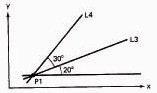
4. By a point and the angle of the line to the x-axis or another line. See Figure A8.6.
L3=LINE/P1, LEFT, ATANGL, 20
L4=LINE/P1, LEFT, ATANGL, 30, L3
Figure A8.6
5. By a point and being parallel to or perpendicular to another line. See Figure A8.7.
L5=LINE/P2, PARLEL, L3
L6=LINE/P2, PERPTO, L3
Figure A8.7

6. By being tangent to two circles. See Figure A8.8.
L7=LINE/LEFT, TANTO, C3, LEFT, TANTO, C4
L8=LINE/LEFT, TANTO, C3, RIGHT, TANTO, C4
L9=LINE/RIGHT, TANTO, C3, LEFT, TANTO, C4
L10=LINE/RIGHT, TANTO, C3, RIGHT, TANTO, C4
Figure A8.8

The descriptive words LEFT and RIGHT are used by looking from the first circle written toward the second circle. For example, another way to specify L7 would be
L7=LINE/RIGHT, TANTO, C4, RIGHT, TANTO, C3
MACHIN: Machine (postprocessor statement). Used to specify the machine tool and to call the postprocessor for that machine tool. In the statement
MACHIN/MILL, 1
the MILL identifies the machine tool type and 1 identifies the particular machine and postprocessor. The APT system then calls the specified postprocessor to prepare the NC tape for that machine.
MACRO: Used to define a suborutine which will be called by the main APT program.
DRILL=MACRO/PX
where DRILL is the symbol for the subroutine and PX is a parameter in the subroutine whose value will be specified when the subroutine is called from the main program. See CALL.
ON: On (motion modifier word) used with three other motion modifier words—TO, PAST, and TANTO—to indicate the point on the check surface where the tool motion is to terminate. See Figure A8.9.
Figure A8.9

OUTTOL: Outside Tolerance (auxiliary statement). Indicates the allowable tolerance between the outside of a curved surface and any straight-line segments used to approximate the curve. See Figure A8.10.
Figure A8.10

Note: The INTOL and OUTTOL statements can be used together to indicate allowable tolerances on both inside and outside of the curved surface. See Figure A8.11.
INTOL/.0025
OUTTOL/.0025
Figure A8.11
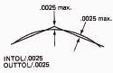
PARLEL: Parallel (descriptive data). Used to define a line or plane as being parallel to another line or plane. See LINE and PLANE.
PARTNO: Part number (auxiliary statement). Used at start of program to idenfity the part program. PARTNO must be typed in columns 1 through 6 of the first computer card in the deck.
PAST: Past (motion modifier word). See ON.
PERPTO: Perpendicular to (descriptive data). Used to define a line or plane as being perpendicular to some other line or plane. See LINE and PLANE.
PLANE: Plane (geometry type). Used to define a plane.
Methods of definition:
1. By three points that do not lie on the same straight line. See Figure A8.12.
PL1=PLANE/P1, P2, P3
Figure A8.12

2. By a point and being parallel to another plane. See Figure A8.13.
PL2 = PLANE/P4, PARLEL, PL1
Figure A8.13
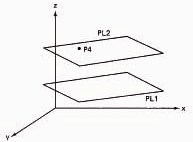
3. By two points and being perpendicular to another plane. See Figure A8.14.
PL3=PLANE, PERPTO, PL1, P5, P6
Figure A8.14

POINT: Point (geometry type). Used to define a point.
Methods of definition:
1. By the x, y, and z coordinates. See Figure A8.15.
P1=POINT/3.0, 1.5, 0.0
Figure A8.15

2. By the intersection of two lines. See Figure A8.15.
P1=POINT/L1, L2
3. By the intersection of a line and a circle. See Figure A8.16.
P2=POINT/YLARGE, INTOF, L3, Cl
P3=POINT/XLARGE, INTOF, L3, Cl
Figure A8.16

Any of the descriptive words—XLARGE, XSMALL, YLARGE, YSMALL—can be used to indicate the relative position of the point. For example, for point P2, YLARGE or XSMALL could be used. For point P3, YSMALL or XLARGE could be used.
4. By two intersecting circles. See Figure A8.17.
P4=POINT/YLARGE, INTOF, Cl, C2
P5=POINT/YSMALL, INTOF, Cl, C2
Figure A8.17
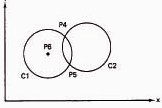
5. By the center of a circle
P6=POINT/CENTER, Cl
RADIUS: Radius (descriptive data). Used to indicate the radius of a circle. See CIRCLE.
RIGHT: Right (descriptive data). See LEFT and LINE.
TANTO: Tangent to (two uses: descriptive data and motion modifier word).
1. As descriptive data, it is used to indicate tangency of one geometry element to another. See CIRCLE and LINE.
2. As a motion modifier word, it is used to indicate that the tool motion is to terminate at the point of tangency between the drive surface and the check surface. See Figure A8.18.
Figure A8.18

TERMAC: Termination of MACRO subroutine. Used as the last statement in the MACRO subroutine to indicate a return to the main program at the statement following the CALL. See MACRO, CALL.
TO: To (motion modifier word). See ON.
TURRET: Turret (postprocessor statement). Used to specify a turret position on a turret lathe or drill or to call a specific tool from an automatic tool changer. Example: TURRET/T30.
XLARGE: In the positive x-direction (descriptive data). Used to indicate the relative position of one geometric element with respect to another when there are two possible alternatives. See CIRCLE and POINT.
XSMALL: In the negative x-direction (descriptive data). See XLARGE.
YLARGE: In the positive y-direction (descriptive data). See XLARGE.
YSMALL: In the negative y-direction (descriptive data). See XLARGE.