Ethernet Frames
In Chapter 1, “Shooting Trouble,” you learned that the protocol data unit (PDU) for Layer 2 is frames. Frames refer to the entire message from Layer 2 to Layer 7. Control bits mark the beginning and end of frames just as picture frames mark the edges of a picture. Because you are already familiar with how Layer 2 allows different devices to take turns on the media (media access control), and how the network works (logical topologies), now I want you to look at how Ethernet data is actually packaged at Layer 2. In particular, compare DIX Ethernet to IEEE Ethernet, including the various Layer 2 headers in Figure 5-3.

Use Figure 5-3 and the Figure 5-4 flowchart as a guide to walk through the Ethernet frames and their headers in the following subsections. Verify the Ethernet frame format details and how the data links change but the upper-layer data remains the same from end to end.

Ethernet II (DIX Ethernet) Frame Format
Figure 5-5 displays Ethernet II (DIX Ethernet) details.

Figure 5-5 shows the following fields:
Preamble (PRE)— Indicates the start of an Ethernet frame, but really not counted as part of the 14-byte frame header.
EtherType— Identifies the encapsulated Layer 3 (see Figure 5-7).
Data— Varies. A 14-byte header + 4-byte trailer cyclical redundancy check (CRC) = 18 bytes. The 46 data bytes + 18 header bytes = 64 bytes. IEEE 802.3 specification includes requirement to pad the data to the 46-byte requirement, but the Ethernet specification really doesn't.
Frame check sequence (FCS)— A 4-byte error detection CRC created by the sender and recalculated by the receiver to check for transit damage. The 1500 data bytes + 14 header bytes = 1514 bytes, or with the FCS (CRC) 1518 bytes.
NOTE
Anything below the minimum of 64 bytes is considered a runt. Anything above the maximum of 1518 is considered a giant. See the “Shooting Trouble with Ethernet” section for more on runts and giants.
Figure 5-6 displays a protocol analyzer trace of an Ethernet II ARP frame. Frame 221 in the Summary pane clearly displays the source address, destination address, summary, and timing summary. The DLC header displays the destination address as broadcast or all FFFFs, the source address as the MAC address of hosta (unicast), and the EtherType of 0x0806, which Sniffer informs you is ARP. Follow through the ARP/Reverse Address Resolution Protocol (RARP) frame to see that an IP Layer 3 address is contained in the message as indicated by protocol type 0x0800. Refer to the Ethernet Frame Types helper chart in Figure 5-4 to help identify the frame as an Ethernet II/DIX frame format just because an EtherType is present. Actually the 0x0800 and 0x0806 EtherType values are both greater than 0x05dc or 1500 bytes decimal, which is the allowed length for an 802.3 frame. Use your scientific calculator to perform the math.

Figure 5-7 displays another example of Ethernet II that displays the EtherType for IP. This is how the Data Link Layer hands off to the next-layer protocol.

In both Figure 5-6 and Figure 5-7, you identify the frame type by looking at the 2-byte EtherType field in the DLC header. The value of the EtherType indicates the next-layer protocol to hand off to. Look up www.cavebear.com/CaveBear/Ethernet/type.html as in Figure 5-8 or http://standards.ieee.org/regauth/ethertype/type-pub.html for more EtherTypes. Cavebear also has a fairly comprehensive list of Ethernet vendor codes and multicast addresses (which are discussed in more detail in the “Ethernet Addressing” section later in this chapter).

NOTE
The maximum packet length for Ethernet is 1500 bytes. If the length field is less than or equal to 1500 (0x5dc, where 0x designates hex) bytes, the frame format is IEEE 802.3 Ethernet. If the length field is not a valid length (greater than 1500), a type field is used and the frame type is Ethernet II. The value of the type field further defines the Layer 3 protocol, such as 0x800 for IP or 0x8137/0x8138 for IPX. Excluding the preamble bytes, 13 and 14 are the determining bytes.
IEEE 802.3 Ethernet Frame Format with Raw (Novell 802.3) Header
Now look at the detailed Sniffer frame format for IEEE 802.3 Raw in Figure 5-9. Remember that IEEE 802.3 Ethernet uses a valid length field (<= 1500 bytes) rather than the EtherType field.

Identify the following fields in a protocol analyzer trace such as the one in Figure 5-10:
Preamble— Indicates the start of an Ethernet frame, but really not counted as part of the 14-byte frame header.
Data— Varies. A 14-byte header + 4 byte trailer (CRC) = 18 bytes. The 46 data bytes + 18 byte header = 64 bytes. IEEE 802.3 specification includes requirement to pad the data to the 46-byte requirement, but the Ethernet specification really doesn't.
Frame check sequence— A 4-byte error detection CRC created by the sender and recalculated by the receiver to check for transit damage. The 1500 data bytes + 14 bytes = 1514 bytes, or with the FCS 1518 bytes.

Figure 5-10 displays an example of an IEEE 802.3 Ethernet frame. Frame 65 that is highlighted in the Summary pane clearly displays the source address, destination address, summary, and timing summary for an IPX ping packet. It is equivalent to the details in the DLC header of the Detail pane. The destination and source addresses are both unicast, as you can verify in the Hex pane at the bottom. Follow through the IPX header to see that the checksum is 0xFFFF, which means that it is not used; this is what you should expect for the Ethernet RAW format. Refer to the Ethernet Frame Types helper chart in Figure 5-3 to see that an EtherType is not present, and the frame does not have an LLC header; you can identify it as IEEE 802.3 RAW.
IEEE 802.3 Ethernet Frame Format with 802.2 SAP Header
Other header types used with the IEEE 802.3 frame format include SAP and SNAP. Figure 5-11 illustrates the IEEE 802.3 Frame Format with an 802.2 (Logical Link Control, LLC) SAP header.

Refer to the preceding subsection for an explanation of the individual fields in the header. The only difference here is that part of the data field is borrowed for the LLC header, which uses Service Access Points (SAPs) to point up to the Layer 3 protocols (see Figure 5-12).

NOTE
Remember that IEEE SAPs differ from the Novell SAPs discussed in the preceding chapter. IEEE 802.3 with a SAP header uses 802.2 LLC SAPs to point to the Layer 3 protocol.
Figure 5-12 illustrates a protocol analyzer trace of an IPX ping using Novell's 802.2 frame type (Cisco's SAP encapsulation), whereas the preceding example used Novell's 802.3 (Cisco's Novell-Ether encapsulation) frame format. The DSAP and SSAP of e0 in the LLC header point to IPX at Layer 3. If they were 06 instead of e0, they would link to IP (see Figure 5-13). For more DSAP (destination) and SSAP (source) values, go to www.cisco.com/warp/public/473/111_12.html.

IEEE 802.3 Ethernet Frame Format with SNAP Header
The final Ethernet frame in Figure 5-14 is an IEEE 802.3 frame with a SNAP header. In addition to the 802.3 Data Link header and the 802.2 LLC header, it contains a SNAP header.

Figure 5-15 illustrates a protocol analyzer trace of CDP as an example of the IEEE 802.3 frame with a SNAP header. Marked frame number 1 illustrates DLC, LLC, SNAP, and CDP headers.
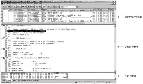
The DLC destination address is multicast address 01000ccccccc, which is reserved for CDP. The DSAP and SSAP of the LLC header are both AA, which indicates that a SNAP header follows as shown. Note the vendor ID of Cisco1 and the SNAP Type of 2000 for CDP. (In the Hex/ASCII window at the bottom, locate the corresponding bytes.) SNAP is like putting the type field back in for various vendors! In point of fact, additional data bytes are borrowed to give more room for proprietary protocols.
NOTE
Because 00000C is an Organizationally Unique Identifier (OUI) reserved to Cisco, 01000Cxxxxxx is the range of multicast addresses also reserved to Cisco. Just as each vendor is responsible for suballocating the lower 3 bytes for unicast source addresses, vendors can do as they want with proprietary multicast MACs.
To summarize, the Ethernet frame format rules concentrate on the 2-byte type/length field (byte 13 and 14 excluding the preamble). If these 2 bytes are >= 0x05dc, it is Ethernet II (DIX). If they are <= 0x05dc and FF FF with no LLC header, it is Novell's 802.3 RAW. If they are <= 0x05dc and AA AA, it is IEEE 802.3 with SAP (LLC) 802.2 and SNAP headers. If they are <= 0x05dc but not AA AA or FF FF, it is IEEE 802.3 frame with a SAP (LLC) 802.2 header.
Encapsulation (frame format) is a likely troubleshooting target on your data links regardless of whether you are using Ethernet, Token Ring, FDDI, High-Level Data Link Control (HDLC), PPP, Frame Relay, ATM, or something else. Although this section has primarily discussed Ethernet frame formats, you can find the other formats at Cisco.com or you can purchase detailed protocol reference guides from sites such as www.hollisterassociates.com/protocol_reference_guides.htm. Another important Layer 2 troubleshooting topic is addressing.