
In this recipe, we will try to convert simple, hand-drawn sketches to vector graphics using image processing functions from the OpenCV library and Cairo library for vector drawing and exporting.
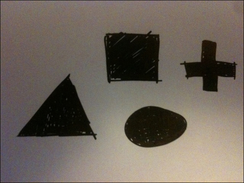
We will be using the OpenCV library, so please refer to the Integrating with OpenCV recipe earlier in this chapter for information on how to set up your project. You may want to prepare your own drawing to be processed. In this example we are using a photo of some simple geometric shapes sketched on paper.
We will create an application to illustrate the conversion to vector shapes. Perform the following steps to do so:
- Include necessary headers:
#include "cinder/gl/Texture.h"
#include "cinder/Surface.h"
#include "cinder/ImageIo.h"
#include "cinder/cairo/Cairo.h"
- Add the following declarations to your main class:
void renderDrawing( cairo::Context&ctx );

Surface mImage, mIPImage;
std::vector<std::vector<cv::Point> >mContours, mContoursApprox;
double mApproxEps;
int mCannyThresh;
- Load your drawing and set default values inside the
setupmethod:mImage = loadImage( loadAsset("drawing.jpg") ); mApproxEps = 1.0; mCannyThresh = 200; - At the end of the
setupmethod add the following code snippet:cv::Mat inputMat( toOcv( mImage ) ); cv::Mat bgr, gray, outputFrame; cv::cvtColor(inputMat, bgr, CV_BGRA2BGR); double sp = 50.0; double sr = 55.0; cv::pyrMeanShiftFiltering(bgr.clone(), bgr, sp, sr); cv::cvtColor(bgr, gray, CV_BGR2GRAY); cv::cvtColor(bgr, outputFrame, CV_BGR2BGRA); mIPImage = Surface(fromOcv(outputFrame)); cv::medianBlur(gray, gray, 7); // Detect edges using cv::MatcannyMat; cv::Canny(gray, cannyMat, mCannyThresh, mCannyThresh*2.f, 3 ); mIPImage = Surface(fromOcv(cannyMat)); // Find contours cv::findContours(cannyMat, mContours, CV_RETR_LIST, CV_CHAIN_APPROX_SIMPLE); // prepare outline for( int i = 0; i<mContours.size(); i++ ) { std::vector<cv::Point> approxCurve; cv::approxPolyDP(mContours[i], approxCurve, mApproxEps, true); mContoursApprox.push_back(approxCurve); } - Add implementation for the
renderDrawingmethod:void MainApp::renderDrawing( cairo::Context&ctx ) { ctx.setSource( ColorA( 0, 0, 0, 1 ) ); ctx.paint(); ctx.setSource( ColorA( 1, 1, 1, 1 ) ); for( int i = 0; i<mContoursApprox.size(); i++ ) { ctx.newSubPath(); ctx.moveTo(mContoursApprox[i][0].x, mContoursApprox[i][0].y); for( int j = 1; j <mContoursApprox[i].size(); j++ ) { ctx.lineTo(mContoursApprox[i][j].x, mContoursApprox[i][j].y); } ctx.closePath(); ctx.fill(); ctx.setSource(Color( 1, 0, 0 )); for( int j = 1; j <mContoursApprox[i].size(); j++ ) { ctx.circle(mContoursApprox[i][j].x, mContoursApprox[i][j].y, 2.f); } ctx.fill(); } } - Implement your
drawmethod as follows:gl::clear( Color( 0.1f, 0.1f, 0.1f ) ); gl::color(Color::white()); gl::pushMatrices(); gl::scale(Vec3f(0.5f,0.5f,0.5f)); gl::draw(mImage); gl::draw(mIPImage, Vec2i(0, mImage.getHeight()+1)); gl::popMatrices(); gl::pushMatrices(); gl::translate(Vec2f(mImage.getWidth()*0.5f+1.f, 0.f)); gl::color( Color::white() ); cairo::SurfaceImage vecSurface( mImage.getWidth(), mImage.getHeight() ); cairo::Context ctx( vecSurface ); renderDrawing(ctx); gl::draw(vecSurface.getSurface()); gl::popMatrices();
- Inside the
keyDownmethod insert the following code snippet:if( event.getChar() == 's' ) { cairo::Context ctx( cairo::SurfaceSvg( getAppPath() / fs::path("..") / "output.svg",mImage.getWidth(), mImage.getHeight() ) ); renderDrawing( ctx ); }
The key part is implemented in step 4 where we are detecting edges in the image and then finding contours. We are drawing vector representation of processed shapes in step 5, inside the
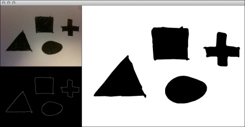
renderDrawing method. For drawing vector graphics we are using the Cairo library, which is also able to save results into a file in several vector formats. As you can see in the following screenshot, there is an original image in the upper-left corner and just under it is the preview of the detected contours. The vector version of our simple hand-drawn image is on the right-hand side:
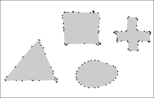
Each shape is a filled path with black color. Paths consist of points calculated in step 4. The following is the visualization with highlighted points:
You can save a vector graphic as a file by pressing the S key. The file will be saved in the same folder as application executable under the name output.svg. SVG is only one of the following available exporting options:
|
Method |
Usage |
|---|---|
|
Preparing context for SVG file rendering | |
|
Preparing context for PDF file rendering | |
|
Preparing context for PostScript file rendering | |
|
Preparing context for Illustrator EPS file rendering |
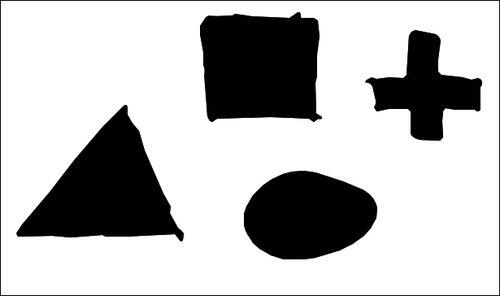
The exported graphics look as follows:
- Cairo: http://cairographics.org/