
CHAPTER 10 Drawing and Editing Objects
If you thought learning to create basic and smart objects in Chapter 8 was fun and a learning experience, hold on: basic shapes will get your work only so far—CorelDRAW’s path-building and editing tools move your cursor toward exactly what you have in mind. The Curve tools group on the toolbox has specific tools for drawing paths of any shape you can imagine, and some you can’t! In the following sections, you’ll work through the process of editing lines and their nodes, so there’s no reason to draw something that’s close to what you need. This chapter is the DRAW part of CorelDRAW.
NOTE
Download and extract all the files from the Chapter10.zip archive to follow the tutorials in this chapter.
Introducing CorelDRAW X5’s Curve Tools
The most basic shape you can draw in CorelDRAW (and in any vector drawing program) is a line: a line is a path that passes through at least two points, called nodes in CorelDRAW. A line is actually a mathematical equation, and as such doesn’t necessarily need an outline color or a width. It doesn’t even have to be a straight line, but it does have a direction—the direction in which you draw the line. Actually, this is where the fun begins, because you can assign a line scores of different properties: arrowheads, a dotted look for coupons, colors, and varying widths galore. Joining the beginning and end points of a line (a path) closes the path, and if the beginning doesn’t meet the end point, the shape is called an open path.
CorelDRAW X5’s Curve tools group is made up of eight virtual pens, shown in Figure 10-1, located between the Zoom/Hand and the Smart tools groups on the toolbox.
The tools are task oriented; although they all produce paths, your choice of tool (s) for a task depends upon what you want to draw. For example, do you need to produce an object whose curves are flawless like those of a physical French curve? This task calls for the new B-Spline tool, although other drawing tools can approximate the same set of curves with a different approach and a little more work. Additionally, the Artistic media tool is prone to producing open paths, not closed ones, and although you can close and fill an artistic media path, if drawing an object you can fill is your goal, you’d choose a tool other than Artistic media. You can also “mix and match”; you can begin an object with one tool, and finish it with a different tool—your choice, or choices, depend on the object you want to create. Some of these tools work similarly, so it’s best to become acquainted with what the cursors look like, as shown in Figure 10-1.
How to Fill an Open Path
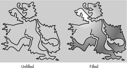
Depending on how your CorelDRAW X5 options are currently selected, open-path objects—in which the beginning and end points are not joined—might not be available to apply a fill color to the inside area of the path, mostly because it has no inside. This might seem an inconvenience if you’re accustomed to using other applications such as Adobe Illustrator that, by default, normally enable open paths to be filled. In CorelDRAW X5, you can fill an open path, but this option is not turned on by default. Options are not set to fill open-ended paths, shown next, automatically, but you can change this if you so choose.
To change CorelDRAW drawing behavior to specify that all open paths be filled— without the need to close the path first—follow these steps:
1. Open the Options dialog by choosing Tools | Options (CTRL+J).
2. Click to expand the tree directory under Document, and click General to display the associated options on the right side of the dialog.
3. Click to select the Fill Open Curves option, and click OK to close the dialog.
After you choose this option, the open paths you draw can have an interior area.
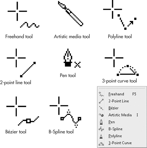
FIGURE 10-1 For visual reference while you work, each of the different drawing tools has a unique cursor.
Using the Artistic Media Tool
The Artistic media tool treats a path as though it’s a skeleton to which you can apply any number of CorelDRAW preset “skins.” There are five different types of artistic media “brushes,” some with preset variations (the Preset, Brush, and Sprayer artistic media types) and some without presets (Calligraphic and Pressure artistic media types). It helps to think of a “paintbrush” metaphor; by dragging strokes, you’ll wind up with anything from complex filigree strokes to elegant calligraphic handwriting. The underlying path to artistic media strokes can be changed at any time, which changes the corresponding look of the media—and you can see the dynamic changes for accurate visual feedback as you work. You can draw while an artistic media effect is enabled, and you can also apply these painterly strokes to existing lines. The Artistic media tool is located in the toolbox with other line-drawing tools.
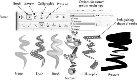
FIGURE 10-2 The property bar offers five different line-drawing modes, each of which has its own options.
With the Artistic media tool selected, the property bar offers five different line-drawing modes to choose from, shown in Figure 10-2, each of which has its own options. You have additional options on the property bar, directly to the right of your choice of artistic media, and the options change, depending on the media type you choose.
Applying Presets to Lines
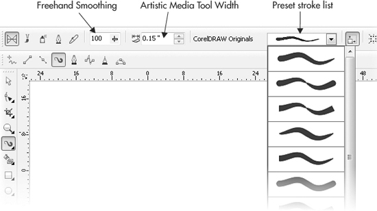
Artistic media is an evolutionary result of CorelDRAW’s Powerlines feature. Veteran users will be the most comfortable with the improvements over Powerlines—now called Presets— and everyone will be delighted with the new diversity of media types. The Artistic media tool surrounds your drawn lines with specific preset vector objects, which are dynamically linked to the underlying path; you choose from the Preset stroke list in the property bar after choosing a media type. The smoothness and width of the applied effect is set according to the Freehand Smoothing and Width options in the property bar, as shown here:
TIP
If you’ve used previous versions of CorelDRAW, you’ll notice that the smoothness with which you draw artistic media strokes has been refined quite a bit; you might not need to adjust your strokes for smoothness at all.
Set the shape using one of the styles in the Preset stroke list. Smoothing is based on percent values between 0 (no smoothing) and 100 (maximum smoothing). Width can be set on a unit measure ranging from 0.03 to 10 inches. As you draw, a path is created in freehand style and immediately applied to your line.
Ready to take the Artistic media tool out for a spin? The following steps walk you through the completion of an illustration—adding cartoon “reaction lines,” the sort of emanations a character has when they’re struck with a revelation—just to get a feel for how the artistic media’s Preset brush works and feels.
 Painting with a Drawing Program
1. Open Cartoon Reaction.cdr in CorelDRAW.
2. Choose Tools | Object Manager to make sure Object Manager is checked. In the Object Manager docker, click “add lines here” to select it as the current editing layer if it’s not already highlighted. The underlying layer containing the cartoon is locked so it cannot accidentally be moved.
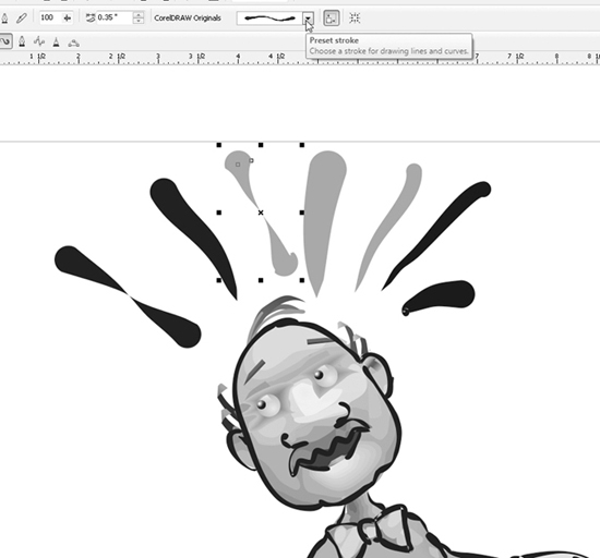
3. Choose the Artistic media tool, then click the Preset icon, the far left button on the property bar.
4. Click the Preset stroke list and choose a style. For this example, choose a style that has a rounded head and that tapers at the end to a point.
5. Think of how you’d draw a cartoon sun; drag strokes so the “sun” is the cartoon fellow’s head. The target width for the strokes is about 0.35″. If your current stroke width is something different, more’s the opportunity to become familiar with artistic media features—while the stroke is highlighted, increase or decrease the width on the property bar.
6. The head of the Preset stroke begins where you begin your click-drag. If you drew a stroke backwards, this is easily fixed. Press F10 to choose the Shape tool, click to select the stroke (you’ll see the red underlying path when the stroke is properly selected), and then right-click and choose Reverse Subpaths from the context menu.
7. Click the Artistic media tool of the toolbox, and you’re ready to continue stroking. The Artistic media tool is persistent—it “remembers” your last-used stroke settings, styles, and all that good stuff.
8. The preset strokes you create are a special instance of an object surrounding a path. You can, therefore, recolor the default black fill. With a stroke selected, try clicking a color well on the Color Palette. The cartoon fellow’s excitement is now in color, as shown in Figure 10-3.
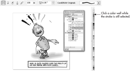
FIGURE 10-3 While a Preset stroke is selected, you can change its width, smoothness, and color.
9. Let’s say you want to get adventurous and change the preset for one of the strokes. If the stroke is selected, you choose a different Preset stroke from the drop-down list… and every subsequent stroke you make will have its style. If you’ve deselected a stroke and want to change it, choose it with the Pick tool, and then use the drop-down list. It’s important that you click the edge of a stroke on the page and not its center. The center of the drawn stroke is the parent—the control curve to which the stroke is applied—and it has no properties like the artistic stroke does. Alternatively, you can click (don’t click-drag, though) a stroke on the page to select it, and then change the Preset stroke. Class dismissed, go answer that doorbell.
TIP
If you’re experimenting and turned the Freehand smoothing down to 0 while painting with the Artistic media tool, the result might be a stroke that has more nodes than you’d like, to create a smooth arc or straight line. At any time, you can choose the Shape tool, click the stroke to reveal its nodes, and then marquee-select all the nodes. Then use the Reduce Nodes spin box on the property bar to remove superfluous nodes along the path that is driving the artistic media stroke.
Drawing with Brushes
In Brush mode, you can simulate the look of traditional, natural media, that looks very similar to the brushes in Corel Painter, with a notable exception. Because beneath an artistic media stroke lies a skeleton path, the strokes you make can be edited ad infinitum. In contrast, bitmap paint programs such as Corel Painter and Adobe Photoshop feature brushstrokes that can’t be edited after making them—it’s a done deal after you paint a stroke. As with the Presets category, artistic media brushes extend the full length of every path you create. Here’s what the property bar looks like, and what your options are, when you choose the artistic media brush:
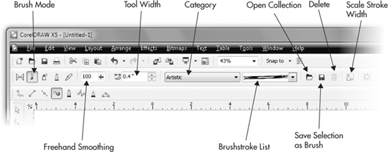
The Brushstroke list box offers a variety of different styles, only six of which are shown in Figure 10-2. Freehand Smoothing and Stroke Width options are used to change the appearance of the graphical object—the “skin”—applied to the underlying path.
CAUTION
As with all trash-can-shaped Delete icons and buttons, don’t click the Delete brush button unless you truly understand the consequences of deleting something (and your decision-making ability can be verified by friends).
You can draw using a brush style, or alternatively, apply one to an existing line. To draw using a brushstroke, choose the Artistic media tool, and use property bar options to choose a brush style. Begin drawing by click-dragging on your page in a stroking motion. To apply a new brushstroke to an existing line, select the line using the Artistic media tool, choose the Brush mode, and use property bar options to choose a width and brushstroke style. You can load saved brushes by clicking the Browse button in the property bar, and save your own objects as brushstrokes and add them to the existing Brushstroke list. This is fun and useful stuff, as the following steps walk you through how to create, save, and use a custom brush.
TIP
By default, saved brushes can be found in C:Users(Your user account name) AppDataRoamingCorelCorelDRAW Graphics Suite X5DrawCustomMediaStrokes.
Creating and Saving Your Own Brushstroke
1. Open Toothpaste ad.cdr. The layer with the image is locked, and the current editing layer should be above it—check Object Manager to ensure this before you begin.
2. Take a look at the light purple grouped object at the lower left of the page. This is a simple example of using the blend effect and then adding a few objects for highlights. Create something similar to this for these steps. See Chapters 8 and 21 if you don’t already know how to build such a drawing; you can use the grouped objects to get right to these steps.
3. Select the shape (s) and then choose the Artistic media tool. Click the Brush button on the property bar.
4. Click the Save icon; save the stroke to whichever folder CorelDRAW offers (to make it easy to find later), give the stroke a name, and then click Save, as shown in Figure 10-4. Brush objects are saved using Corel’s standard presentation file format (CMX). The next time you choose the Artistic media tool’s Brush, a thumbnail preview of your custom brush is at the top of the drop-down list.
5. After you click Save in the Save As dialog, your new brush is immediately available for use. Try slowly click-dragging the brush above the toothpaste to write “New”; try stroking a daub of toothpaste on the toothbrush. The only thing you should watch out for is creating sudden changes in direction with your stroke, especially when the brush contains several small objects, as this toothpaste custom brush does. The brush has a difficult time negotiating sudden direction changes in the underlying path, and you might find unappealing corners in the resulting brushstroke.
6. Tutorial’s done. Don’t forget to brush twice a day.
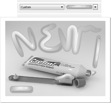
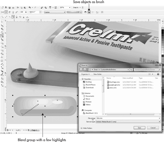
FIGURE 10-4 The easiest part of building a custom brush is saving it.
Applying the Sprayer
The Artistic media tool’s Sprayer mode is used to pepper the drawing page with a sequence of drawings, either by using your own that you save as a brush, or by choosing a preset from CorelDRAW’s Sprayer collections. The Sprayer is quite like the Image Hose in Corel Painter, except changes to the underlying path and the objects used in a spray can be dynamically made at any time. The Sprayer objects repeat uniformly or randomly across the full length of a path. The Size/Scale, Spray Order, Dabs, Spacing, Rotation, and Offset values can be set using the property bar, shown in Figure 10-5.
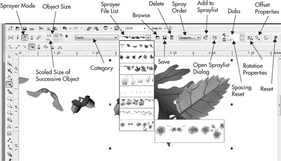
FIGURE 10-5 The Sprayer mode of the Artistic media tool offers a huge number of design variations.
Here’s what the Sprayer property bar options give you control over:
• Object Spray Size/Scale These two options control the initial object size of the sprayer style (the objects that make up a specific spray type) based on a scaled percentage of the original spray object selected. When the Size/Scale options are locked, you can set the scaling of successive objects to be increased or reduced in scale relative to the size of the first object in the sprayer style.
• Spray Order This option lets you set the ordering of the sprayer objects: Randomly, Sequentially, or By Direction. If the sprayer style features only one object to vary, changing this option has no effect. Try the mushrooms preset; the Spray preset contains several different objects of different sizes, and you can get different looks by choosing Randomly and By Direction.
• Dabs and Spacing These two values set the number of objects to be placed along a drawn or existing path and the distance between the centers of each object. Dabs are the individual objects in the sprayer style; Spacing controls how many objects appear within a given distance. Think of Spacing as “population.”
• Rotation This option is used to set the angle for the first object of the sprayer style. The Increment option is used to compound rotation values for each subsequent object. Rotation angles and increment values can be based on the degree measure relative to the page or the path to which the objects are applied. For example, if you need a circular pattern whose objects are oriented toward the center of the circle, the rotation option is the ticket.
• Offset This option sets the distance between the path you click-drag and the sprayer objects. Offset can be set to be active (the default) at settings between roughly 0.01 and 13 inches. The direction of the offset can also be set to Alternating (the default), Left, Random, or Right. To deactivate the Offset options, uncheck the Use Offset option in the selector, which sets the Offset measure to 0.
• Reset Clicking this button returns all sprayer style settings in the property bar to their original default settings.
As with other Artistic media tool modes, you can draw while applying this effect, or apply an artistic media stroke to an existing line.
With a sprayer style applied and the line selected, you can use property bar options to edit the effect. Doing this edits the style only as it is applied to your line and not in the original style in the Sprayer file list. Figure 10-6 shows a sampling of the available sprayer styles applied using default settings.
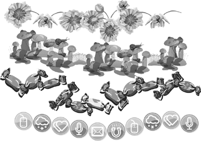
FIGURE 10-6 These are a few of the sprayer styles available in CorelDRAW X5.
TIP
To create your own Sprayer brush, first open the Artistic media docker (Window | Docker | Artistic Media). Create several shapes—they can be groups of objects, and they can contain any fill you like—and then arrange them horizontally on the page. Select them, and then click the Save button at the bottom of the docker. Saving and choosing sprayers to use is almost identical to the way you save and use brushes.
Calligraphy Pens and Applying Media
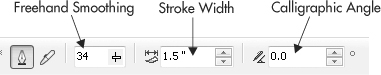
The Calligraphy tool mode produces results similar to adjusting the nib shape with any regular Pen tool; however, the width and angle can be conveniently changed dynamically when you use the Calligraphy tool. Additionally, your artistic approach with this tool is different than with drawing paths—you click-drag to produce an entire stroke instead of click-dragging to set a node and a path segment.
You have three options on the property bar when Calligraphic is selected: the Freehand smoothing (the degree of accuracy when you click-drag); the Stroke width, which sets the maximum width (because calligraphic stroke are alternately thick and thin); and the Calligraphic angle (increasing values in this field rotates the stroke evaluated from the vertical in a counterclockwise direction).
If you use a mouse as an input device instead of a digitizing stylus, using the Calligraphy tool to draw elegant curves and handsome signatures becomes problematic. A mouse simply cannot express the degree of accuracy a tablet and stylus do. This doesn’t have to be an obstacle to creating calligraphic designs, however. Follow this tutorial to learn how to apply a Calligraphic property—and any artistic media except Pressure—to an existing path.
Defining and Applying Calligraphic Brushstrokes
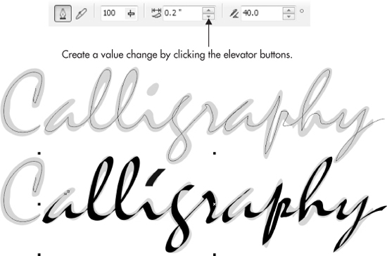
1. Open the Calligraphy.cdr file. There is a thin centerline on the top, unlocked layer. The bottom layer is just for reference. Mistral was used as the typeface and is a good example of calligraphic swoops, curves, and turns. Keep reading this chapter to learn how to guide a pen tool to create a similar centerline trace over a typeface.
2. With the Pick tool chosen, select the lowercase a after the initial C.
3. Choose the Artistic media tool, and then click the Calligraphic tool on the property bar. Do not deselect anything.
4. Here’s the trick: click either the up or down elevator button to the right of the Width field (or type .2 or .1 in the field instead of using the elevator buttons). What you’ve done is get the Calligraphic pen to “recognize” that you want to change a value of the selected path’s calligraphic width. The change isn’t important, it’s the recognition that applies the calligraphic property to the selected stroke.
5. Continue to adjust the Width (.2″ works well at the path’s scale here), and then play with the Angle—anywhere from 35° to 55° will look good in this example.
6. Because you began with an existing stroke, the calligraphic treatment has an outline and no fill. Click the black color well on the Color Palette, and then right-click the No Fill color well to remove the outline.
7. Perform steps 2–6 with the initial C, and then with the brush, dot the i.
Pressure Mode
The last of the artistic media modes was created for users of digital tablets; if you own a stylus and tablet, you can set up the drivers for the stylus to apply pressure, and CorelDRAW will read stylus pressure to vary the width of the stroke as you drag across the page. You have Freehand smoothing and Width controls on the property bar.
If you’re using a mouse, you can:
• Hold the DOWN ARROW key to make the line smaller as you drag.
• Only after using the DOWN ARROW key, press the UP ARROW key to widen the stroke as you click-drag. The maximum width is the value in the num box, and you cannot exceed this width, so plan ahead.
Honestly, don’t expect world-class art using the mouse and arrow keys; you might run into a design situation where you need to vary the width of a stroke, but there are other ways to edit an existing stroke that produce more refined results.
How to Draw in CorelDRAW
Using artistic media is fun and useful, but it’s now time to learn how to build paths instead of brushstrokes. In the same group of Curve tools, you’ll find CorelDRAW’s path and node creation pens. They’re used for both accuracy and artistic expression, and they have varying degrees of ease of use that correspond directly to their power.
Drawing with Freehand and Polyline Tools
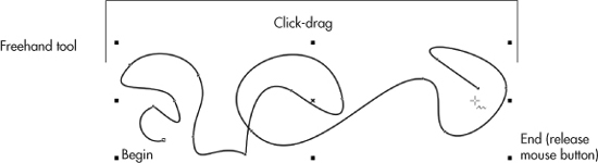
The Freehand and Polyline tools share a common function, giving you the freedom to draw as if you were sketching by freehand on a physical sketchpad, but the tools work in slightly different ways. Sketched lines can create a single open or closed vector path. Both tools are in the toolbox, grouped with other line-creation tools. For mouse users and stylus users alike, click-dragging initially produces a start node for a path segment and then a path segment that follows; a node is placed when you release the mouse (or stylus) button, setting the end of the path segment. To use these tools:
1. Begin by selecting either the Freehand or Polyline tool. Your next step depends on which tool you choose.
2. If you chose the Freehand tool, you can create a continuous line by click-dragging a path shape. As soon as the mouse button is released, the line is complete, shown next. To draw a straight line between two points, click once to define the start point and a second time somewhere else to define the end point. As soon as you release the mouse button, the curve is complete.
3. If you chose the Polyline tool, the technique is slightly different. Use a click-drag action to create a continuous freehand-style line, but after you release the mouse button, your cursor can continue extending the curve with path segments. You click-drag to freehand-style extend the path, or single-click to add a straight line path segment. A double-click action at your final point defines it as the end point.
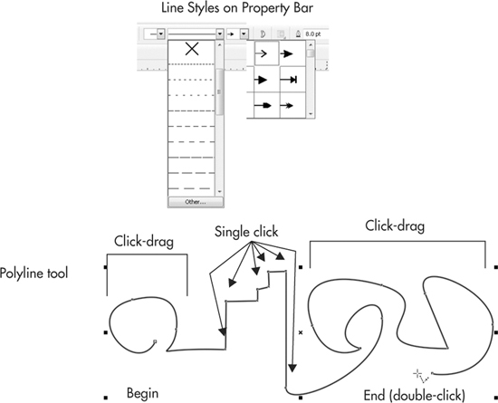
4. Both tools produce “bare bones” paths—no fancy strokes, no elegant calligraphic varying widths. This means you can use the property bar options to make your path begin with an arrowhead, make the line a dashed line, and change the stroke width.
Using either of these line tools, you have control over the smoothness of path shapes drawn using click-drag actions by adjusting the Freehand Smoothing option in the property bar before drawing your path. You can control smoothness after drawing a path by selecting nodes with the Shape tool and then using the Reduce Nodes spin box. Reduce Nodes has a range between 0 and 100 percent; lower values apply less smoothing, and higher values apply more smoothing, as shown in Figure 10-7.
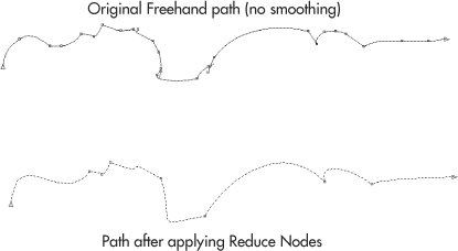
FIGURE 10-7 Freehand Smoothing and Reduce Nodes can change a crude drawn line into smooth curves.
Drawing Arcs with the 3-Point Curve Tool
The 3-point curve tool was created for artists to build perfectly smooth arcing line segments, with complete control over the direction and steepness of the curve between two points. Making a smooth arc is accomplished in three steps, and you can then extend the curve by beginning a new 3-point curve at the first curve’s end point, to then close the two curves as a single object.
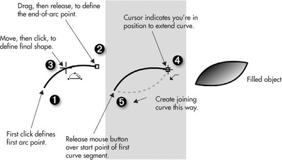
You’ll quickly discover that part of the power of the 3-point curve tool is its use in building a series of connected arcs: you can design French curves and ornamental borders by designing a 3-point curve, positioning your cursor over the end point until you see the cursor signifying an extension of the last-drawn curve, and then building another 3-point curve. This is how the head, eyes, and pupils of the cartoon tabby cat in Figure 10-8 were drawn. Open Ginger tabby.cdr and take the 3-point curve tool out for a spin; Ginger tabby finished.cdr is the completed illustration you see here. The goatee was drawn using the artistic media Brush mode.

FIGURE 10-8 You can create smooth, connecting arcs quickly by using the 3-point curve tool.
Using the Bézier and Pen Tools
The Bézier tool and the Pen tool are variations on the same theme of drawing connected curves and straight segments (unlike the 3-point curve tool) through the action of first clicking to set a path point, and then either dragging to define a curve behind the click point, or by clicking (no dragging) to define a straight path segment behind the click point. You’ll find these tools grouped together with other line-drawing tools.
One of the less obvious differences between the two tools is that the Pen tool offers a “look ahead” point when you draw with it: before you click or click-drag a point, the proposed path between the point before you click and the previous (already defined) point on the path is shown in light blue. When you’re just beginning with CorelDRAW, the choice between these tools might seem to be:
• The Pen tool provides intuitive results when you want a path that has both straight segments and curves.
• The Bézier tool excels at creating curved segments that are joined smoothly, and when straight segments are not your design goal.
The Science of Béziers
Bézier curves (pronounced bezz-ee-aye) were named after French engineer Pierre Bézier, who published papers on their use after seeing the need for mathematically describing very smooth curves that are easy to manipulate, to design automobile bodies. A Bézier curve is a parametric curve, which means it approximates a curve through 2D space, using a convex control hull that can be described by two points on a curve, and two points off the curve (called control handles in CorelDRAW) for intuitively reshaping the curve. The Bézier tool by its nature creates smooth connections between path segments, through the action of click-dragging to set a path point while at the same time defining the slope of the curve segment that is created behind the newly created point. When control points are on a curve, they are called nodes in CorelDRAW. You can also create straight path segments between curves by using the Bézier tool; it’s a matter of technique. Click-dragging creates smooth curves that have smooth connections between segments, and the act of clicking without dragging sets a path point that is not smooth—if you click again in a different location, a straight path segment is the result.
Because the Bézier tool can produce both curved and straight path segments, there is almost no distinction between the terms line and curve in the discussions in this chapter. The shapes of Bézier lines are controlled in part by node properties and by the position of curve handles. Two paths can have nodes in the same relative page position, but they have completely different shapes (as shown in Figure 10-9).
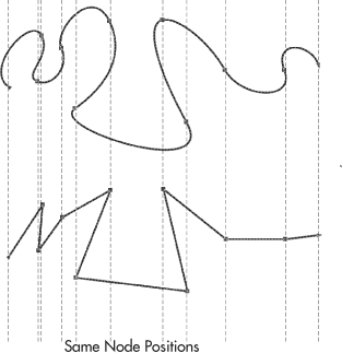
FIGURE 10-9 These two paths each have the same relative node positions, but node properties make them appear completely different from each other.
Nodes and Control Points
Depending on the type of math used to describe a vector path, nodes (points) connect a beginning and end point, and the nodes have control handles, at the end of which are control points, the screen element you use to manipulate curves. The number of control handles and points depends on the segment connected by each node. For example, an arc (a curve) connected to a straight line segment has one control handle visible, and it controls the slope of the curve segment. When two curve segments are connected, you’ll see two control handles if you click the connecting node with the Shape tool, and this node can have different connection properties (cusp, smooth—described later in this chapter). A straight path segment can be described as two nodes connecting the segment, and the control handles for the nodes coincide in position with the node itself. For all intents and purposes, the control handles can’t be seen; they become visible when the segment is changed to a curved segment. The control handles appear on the segment, and you can move them away from the launch point of the curve and then freely manipulate the slope of the curve by dragging the control points.
Nodes can be defined as Cusp, Smooth, or Symmetrical, as shown in Figure 10-10. Cusp nodes can be used to create a discontinuity in direction between two line segments; in English, the two segments connect in a non-smooth fashion. Think of the moon being on the cusp; it’s crescent shaped and this is the sort of shape you can create using cusp node connections. Smooth nodes cause the path slope and direction to align on either side of a node; their relationship is in 180-degree opposition, which has the effect of creating a smooth transition at the node point itself. Control handles surrounding a smooth node may be unequal distances from the node. Symmetrical nodes are not only smooth, but the control handles are also of equal distance from the node. You’ll immediately appreciate the effect of a symmetrical node; when you drag one control point away from a node, the opposing control handle moves an equal distance from the node in exactly the opposite direction. The artistic effect is that the two joined path segments take on an almost circular appearance, which is very useful for technical illustration work.
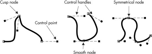
FIGURE 10-10 These paths use different node connection properties.
Drawing with the Bézier and Pen Tools
Both of these tools are used to create compound paths (segments connected by a common node) by combining a series of clicks or click-drags, but each is used in slightly different ways for different results. Using either of these tools, single-clicks define new node positions joined by straight segments. Curve segments are created by clicking to define the node position, and then dragging to define the curve shape. Click-dragging in succession creates a continuous curved path shaped by multiple nodes and off-the-curve control handles. While using the Bézier tool, each click-drag defines and completes the curve segment. A little differently, while using the Pen tool, the cursor remains active, and a preview of the next curve segment appears, so you can define both the curve shape and the next node point. Double-clicking ends the series of path segments.
TIP
When drawing with the Bézier tool, holding CTRL as you click to create new nodes constrains their position to align vertically, horizontally, or within constrained angles relative to the last created node position. Holding CTRL while dragging curve handles constrains their angles to 15-degree increments relative to the last node created.
Let’s try out a new drawing method.
Drawing Curves and Straight Line Segments
1. Choose either the Bézier tool or the Pen tool, and use a single click to define the first node position of your path. Click again to define a second point somewhere else on your page. The two nodes are now joined by a straight line.
2. Using the click-drag mouse technique, click to define your next node position, but continue dragging in any direction. As you drag, the second and third nodes are joined by a curved line.
3. If you chose the Bézier tool, you’ll notice that two control handles appear joined by a dotted line. The point you are dragging is the control point that steers the control handle. The farther you drag the control point from the node, the larger the arc of the curve becomes. Release the mouse button and notice that the control handles remain in view, and your path is complete unless you’d like to move a node or refine the position of its control points some more.
4. If you chose the Pen tool, you’ll notice that a preview of your next curve appears as you move your cursor, which remains active until the next node is defined. To specify a node as the last in the path, double-click to define the current node as the last point.
5. Using either tool, click your cursor directly on the first node you defined. This action closes the path and automatically joins the first and last nodes.
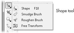
Editing Bézier Paths
All lines are controlled by properties of the nodes they include, which are edited using the Shape tool (F10). You’ll find this tool, shown next, grouped with the Smudge Brush, Roughen Brush, and Free Transform tools.
Using the Shape tool, you can change node positions and curve shapes by click-dragging the nodes, their control points, and by directly click-dragging on a path segment. While using the Shape tool, icons appear on the property bar when one or more nodes are selected; you can select several nodes to change by marquee-dragging them or by SHIFT-clicking a few. These icons are used to set node attributes to Cusp, Smooth, and Symmetrical; to join node and break nodes to create individual path segments; and to create straight lines from curves (and vice versa) when you’ve selected a segment or a node connecting segments. The bevy of additional functions on the property bar provides exceptional control and flexibility in your design work. In short, get to know the functions for the Shape tool! The options are called out in Figure 10-11.
Each of these buttons changes the selected nodes, lines, and curves in specific ways. The following is a description of what the icons do and what they’re called:
• Shape Tool Selection Mode New to CorelDRAW X5, this mode can be used to marquee-select nodes the way users always have, by click-dragging a rectangular shape around the nodes you want to select, or by using Freehand style, which produces a lasso-like marquee you can use to be exacting about which nodes in a group you want to edit.
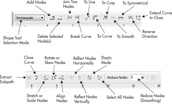
FIGURE 10-11 The property bar offers comprehensive control over path and node properties.
• Add/Delete Nodes These buttons give you the power to add new nodes to a curve or to delete selected nodes after you’ve drawn a path, using the Shape tool and clicking at specific points on a path. To add a node, click any point on a line to highlight the new position, and then click the Add Node button. You can also add a new node to a line by clicking one or more nodes, and then clicking the Add Node button to add a node midway between the selected node and the next node on the path. Pressing the plus (+) key on your numeric keypad achieves the same thing, and you might find this a quicker method. To delete a node, click to select it with the Shape tool, and click the Delete Node button. You can also marquee-select (drag diagonally with the Shape tool to create a rectangle surrounding the nodes) and then delete all the selected nodes in one fell swoop. Pressing the minus (-) key on your numeric keypad or your DELETE key also deletes selected nodes.
• Join Two Nodes/Break Curve When two unconnected nodes on an open path are selected, for example, when the start point is close to the end point, clicking the Join Two Nodes button connects them to create an unbroken path. On single paths, only the unjoined beginning and ending nodes may be joined. On compound paths (paths that aren’t necessarily close to one another, but that have been joined using the Arrange | Combine command), the beginning and ending nodes selected on two existing—but separate—paths can also be joined. While a single node is selected or while a specific point on a segment is clicked, clicking the Break Curve button results in two nodes becoming unjoined, in turn breaking a closed path into an open path.
TIP
Unjoined paths are not the same as separate objects. Two paths, for example, can be located nowhere near each other on a page and yet still be part of a single path. If you want to break a path into its component subpaths, you first select the nodes using a marquee-selection technique with the Shape tool, click the Break Curve button, and then choose Arrange | Break Curve Apart. Pressing CTRL+K is the shortcut, and it’s one of a handful of essential CorelDRAW shortcuts you’ll want to commit to memory.
• Convert Line to Curve/Convert Curve to Line These two buttons are used to toggle the state of a selected straight line to a curve state, and vice versa. A single click with the Shape tool selects a line or curve indicated by a round black marker on the line. When curves are converted to lines, the path they follow takes on a shortcut (as in “the shortest distance between two points”); when converting a straight line to a curve, the path remains the shape, but control handles appear directly on the “line,” and the quickest way to make the control points visible is to drag on the line to force it into a curve shape. When a curve is selected, you can also adjust the shape of the curve using a click-drag action at any point on the curve and dragging to reposition the path followed by the curve.
• Extend Curve to Close For this command to be available, you must have both the beginning and ending nodes of an open path selected (marquee-select the points, or SHIFT-click to select them both). Under these conditions, clicking the Extend Curve To Close button joins the two nodes by adding a straight line between them and closes the path.
• Close Curve While an open path is selected, clicking this button joins the beginning and end nodes to form a closed path by adding a new straight line between the two nodes; it’s a similar command to Extend Curve To Close, but depending on the closeness of the start to the end path nodes, you might not even see a visible straight line connection. You can also join the end points of a selected curve by using the Close Curve option in the Object Properties docker opened by pressing ALT+ENTER; then click the Curve tab to find the Close Curve check box.
• Reverse Direction While a curve path on a line is selected, clicking this button has the effect of changing the direction of the path. By doing this, the start point of the path becomes the end point (and vice versa). The results of using this command button are most noticeable when the start or end of the line or path has been applied with an arrowhead, meaning the arrowhead is applied to the opposite end of the line or path. You may also notice subtle changes in the appearance of line styles applied to a path after using this command button.
TIP
In addition to making arrowheads point in the right direction, Reverse Direction is also a handy way to enforce PostScript conventions when you print to a PostScript printer. Adobe Systems’ PostScript language is a page description language that has very fixed and definite rules about the direction of paths in a compound shape, such as the letter o. If your compound path o appears to be filled and not hollow, it’s not “speaking” PostScript language. You click the subpath of the compound path, reverse the path direction using this button, and the o will then print properly.
• Extract Subpath This option becomes available only when a compound path is selected by clicking one of its nodes with the Shape tool. After you click the Extract Subpath button, the selected path is separated from the compound path, converting it to a separate path. Using this command on a compound path composed of only two different paths is essentially the same as using the Break Apart command. It’s more useful when you need to extract a specific path from a compound path made up of three or more paths.
• Stretch or Scale Nodes This is a very powerful CorelDRAW feature not available in competing applications. When at least two nodes on a path are selected, clicking the Stretch Or Scale Nodes button allows the transformation between nodes using their relative distance from each other vertically, horizontally, or from center. Eight selection handles become available, just as with object selection using the Pick tool, and you can use a click-drag action from any corner or side selection handle toward or away from the center of the node selection. Holding SHIFT constrains the stretch or scale operation from the center of the selection.
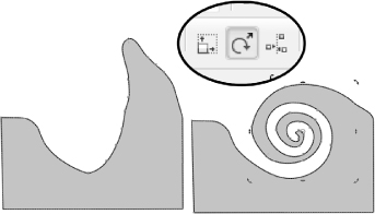
• Rotate or Skew Nodes Similar to Stretch Or Scale Nodes, when at least two nodes on a path are selected, clicking the Rotate Or Skew Nodes button lets you rotate or skew the selected nodes; this is a great feature for refining a shape just a little, and also for creating more dramatic appearance changes (see the following illustration). Eight selection handles appear, and you can click-drag from any corner selection handle to rotate the nodes in a circular direction either clockwise or counterclockwise. Dragging from any side handle enables you to skew the node selection either vertically or horizontally.
• Align Nodes When two or more nodes are selected, clicking this button opens the Align Nodes dialog, where you choose among the Align Vertical or Align Horizontal options that automatically align your node selection accordingly. In addition to these options, while only the beginning and ending nodes of an open path are selected, you can also choose to align control points. This has the effect of moving the two end points of the line to overlap each other precisely. This is a wonderful command for quickly sketching a zigzag (perhaps for an illustration of a saw blade), and then in one step, aligning the nodes to create a precise illustration.
• Reflect Nodes Horizontally/Vertically These two buttons become available when two or more nodes are selected. You use these options to move nodes by using nudge keys (the UP ARROW, DOWN ARROW, LEFT ARROW, and RIGHT ARROW keys on your keyboard) or using click-drag actions in opposite directions.
TIP
To quickly access the same eligible Shape tool node and curve commands available using buttons in the property bar, right-click the nodes or segments of a path, and choose commands from the pop-up menu.
• Elastic Mode With this command, you move selected nodes according to their relative distance from each other; the effect is like experimenting with a rubber band. For example, while a collection of nodes is selected, dragging one of the nodes causes the others to be dragged a shorter distance in relation to the node that is being dragged. While Elastic mode is off, all the selected nodes are moved equal distances. Try this option to add a more organic and natural feeling to a drawing you might feel looks a little too studied and stiff; it adds expression to a path.
• Reduce Nodes When you use this command, CorelDRAW evaluates the overall shape based on the nodes you’ve selected, deletes nodes that deviate from a predictable course along the path, and then repositions the remaining nodes—the effect is to smooth the curve. For past CorelDRAW users, this was called the Curve Smoothness slider. To use this feature, select the nodes controlling the segments you want to smooth, and drag the Reduce Nodes slider control position toward 100. As you drag the slider, the shape of the curves becomes smoothed, and you’ll notice that superfluous nodes disappear from the curve. This option is useful for smoothing lines drawn using the Freehand tool with either the mouse or a digitizing tablet stylus.
• Select All Nodes This button selects all the nodes in a path (or compound path) using one click. It’s a great feature for users who aren’t expert with the marquee-selection dragging technique yet. You may also select all the nodes in a path with the Shape tool by holding CTRL+SHIFT and clicking any node on the path.
TIP
To quickly switch from Rectangular to Freehand node-selecting mode, hold ALT. Any nodes located within the area you lasso are selected.
Are you ready to test-drive the Shape tool? Follow along here.
Editing Paths with the Shape Tool
1. Choose the Ellipse tool (F7) and create an ellipse of any size. Convert the ellipse shape to curves (CTRL+Q) to create a closed path with four nodes joined by four curved lines.
2. Choose the Shape tool (F10). Notice that the property bar now features all the line and node command buttons. Click the Select All Nodes button to select all nodes on the path.
3. With the nodes still selected, click the Add Node button (or press the + key on your numeric keypad). Notice that four new nodes are added midpoint between the four original nodes.
4. Click any of the segments once, and click the Convert Curve To Line button. The curve is now a straight line, and the curve handles have disappeared.
5. Click a node on one of the other existing curves, drag either of the curve handles in any direction, and notice how they change the shape of the path.
6. Using a click-drag action, click near the middle of the curve segment and drag in any direction. As you drag, the curve handle positions at both ends move, and the shape of the curve is changed accordingly.
7. Click any node on the path to select it, and first click the Cusp Node button, and then click the Smooth Node button. Drag the curve handle of this node in any direction. Notice that the curve handle may be dragged only in a single direction. Click the Cusp Node button, and then perform the same action. Notice that the lines on either side of the node can be curved in any direction independently of each other.
8. With this node still selected, click the Break Curve button to split the path at this point. Although it may not be obvious, two nodes now exist where the original node used to be. Drag either of these nodes in any direction to separate their positions. The nodes are now control points because they break the path to form beginning and end points.
9. Select one of these nodes, hold SHIFT while clicking the other, and click the Extend Curve To Close button. Notice the curve is now closed again, while the two nodes have been joined by a straight line.
10. Undo your last action (CTRL+Z) to unjoin the nodes and, while they remain selected, click the Align Nodes button to open the Align Nodes dialog. If they aren’t already selected, click to select all three options (Align Horizontal, Vertical, and Control Points) in the dialog, and click OK to align the points. Notice that they are positioned to overlap precisely. Click to select both nodes, and click the Join Two Nodes button in the property bar. Your path is now closed, and the nodes are joined.
11. Hold SHIFT and click to select two or more nodes on your path. With your nodes selected, click the Stretch Or Scale Nodes button, and notice that eight selection handles appear around your node selection. Hold the SHIFT key (to constrain from center), and drag one of the corner handles toward or away from the center of the selection. All node positions are scaled relative to each other’s position, and the lines joining the unselected nodes also change shape.
12. With the nodes still selected, click the Rotate Or Skew Nodes button in the property bar. Notice that eight rotate and skew handles appear around your selection. Drag any of the corner rotation handles either clockwise or counterclockwise to rotate the nodes. Notice that they are rotated relative to their current position, and the lines joining the unselected nodes also change shape.
The preceding tutorial is only a sampling of what can be accomplished when editing nodes using the Shape tool. You’ll want to invest some quality time practicing your editing skills using all the available node-shaping command buttons, because the payoff is better artwork, artwork that’s closer to what you have in your head, and in the long run, you’ll save time creating wonderful pieces.
TIP
To set the drawing behavior of the Freehand and/or Bézier tools, double-click either of their tool buttons in the toolbox to open the Options dialog to the Freehand/Bézier tool page. Options are discussed in the next section.
Controlling Freehand and Bézier Tool Behavior
The settings to control how Freehand and Bézier tools create the curves and lines you draw are set using a series of options in the Freehand/Bézier Tool pane of the Options dialog, shown next. To access these options, choose Tools | Options (CTRL+J), expand the tree subdirectory under Toolbox, and click Freehand/Bézier tool. The quick way to get to this box is to double-click the Freehand or Bézier tool buttons after choosing them from the Curve tools group.
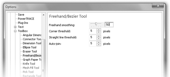
Here’s how the options work:
• Freehand Smoothing The Freehand Smoothing option enables you to set the default value of the Freehand Smoothing option in the property bar while drawing with the Freehand tool. Smoothing may be set based on percent within a range between 0 (minimum smoothing) and 100 (maximum smoothing). This option is largely redundant with the Freehand Smoothing option available in the property bar when a curve and the Shape tool are selected.
• Corner Threshold This option is for setting the default value for corner nodes when drawing with the Freehand or Bézier tool. Lower values cause nodes to be more likely set to cusp nodes, and higher values cause them to more likely be smooth nodes. The range may be set between 1 and 10; the default is 5.
• Straight Line Threshold This option pertains to how the shapes of lines or curves are created when drawing with the Freehand tool. Lower values cause nodes to be more likely set to straight lines, while higher values cause them more frequently to be curved. The range may be set between 1 and 10; the default is 5.
• Auto-Join This option sets the behavior of the Freehand or Bézier tool while drawing closed-path objects. This value represents the distance in pixels your cursor must be when clicking near the first node of a newly created path to close the path automatically. Auto-Join can be set anywhere within a range between 1 and 10 pixels; the default is 5 and is probably the best overall choice for large screen resolutions commonly run today.
Working with Compound Paths
Compound paths have at least two separate paths (either open or closed) composing a single shape. To examine an example of a compound path, use these steps:
1. Choose the Text tool (F8), click once to define a text insertion point, and then type an uppercase Q character. You can assign the character any typeface you like; the more ornamental the character, the more obvious the compound path soon will be. This character shape shown in Figure 10-12 has two paths that are combined: one represents the “positive” space, and one represents the “negative” space shape.
2. While the text object is selected, convert it to curves (CTRL+Q). The status bar now indicates the object is a Curve on Layer 1.
3. Change your view to Wireframe; choose View | Wireframe.
4. Press CTRL+K (Arrange | Break Curve Apart). With the Pick tool, click an empty area of the page, and then click one of the objects and drag it to move it; clearly the two paths are now separate. As shown in Figure 10-13, you have just converted a compound path featuring two subpaths into two individual objects. Go back to View and restore your view quality to Enhanced.
Combining Objects
When separate objects are combined, they behave as a single object. When two or more closed paths are combined, they form positive and negative spaces within the object. Applying a fill to this type of object causes the positive shapes to be filled, and the negative shapes remain clear, as shown in Figure 10-14. You can use the Combine command by choosing Arrange | Combine, or by using the CTRL+L shortcut. You can also click the Combine button in the property bar, or choose Combine from the pop-up menu.
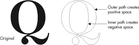
FIGURE 10-12 In vector artwork, “holes” in objects are achieved through compound paths, paths that are combined to create a single object.
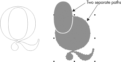
FIGURE 10-13 Break a compound path apart to work with the component objects.
Combining objects that normally feature unique properties—such as rectangles, ellipses, polygons, and perfect shapes—permanently converts them to curves.
NOTE
If you intend to output to PostScript, it might not be a good idea to combine paths that overlap each other. Again, it’s one of the limitations of the PostScript page description language—in human terms, a PostScript printer or image-setting device gets “confused” when a single closed path intersects itself; the device doesn’t know which areas to fill and which to leave empty. If you have a design need for a shape that looks like it self-intersects, ensure proper PostScript output by using the Shaping docker or the buttons on the property bar when multiple objects are selected using the Pick tool to create the illusion of a self-intersecting object.

FIGURE 10-14 You can make two or more separate objects into a single compound path with the Combine command.
Breaking Paths Apart
You can separate the individual paths in a compound path using the Break Curve command (CTRL+K). This command is available when a compound path composed of at least two subpaths is selected. (Using the Extract Subpath command button in the property bar also does this, but only for the selected path.)
Converting Objects to Curves
Converting special types of objects to curves—such as shapes auto-created with the Rectangle and Ellipse tools—frees them to be manipulated with the Shape tool as if they were ordinary paths. Choose Arrange | Convert To Curves, press CTRL+Q, click the Convert To Curves button in the property bar, or right-click the object and choose Convert To Curves from the pop-up menu.
Converting an object to curves removes any special editing properties; text loses its ability to be edited as text, and rounded rectangles can no longer be edited to refine the curvature of the rounded corners. Converting to curves applies to polygon, ellipse, artistic text objects, and certain effects objects such as envelopes and perspective effects.
In this chapter, you’ve seen different tools for creating paths, but the results are more or less the same; objects have path segments and nodes, and paths can be open or closed. You’ve also learned how to edit paths using the Shape tool. You’d be well served to bookmark this chapter; there’s an awful lot of power in CorelDRAW’s drawing and editing tools, and this chapter can be a good reference in the future. After all, the program isn’t called CorelFILL or CorelRECTANGLE—drawing is what good vector design is all about.