
CHAPTER 11 Editing Objects
Let’s say you’ve drawn an object and you’re fairly pleased with it, except for that little corner that you couldn’t draw just right. Editing objects is the theme of this chapter, where you’ll learn various techniques to massage that almost-perfect shape into exactly the shape you’ve envisioned. Because every object you draw on a page can be broken down into rectangles, ovals, path segments, and so on, this chapter covers the tools and features for doing exactly this: breaking down shapes, combining them, subtracting a little of this, adding a little of that. Often, arriving at a design of your dreams can be most quickly accomplished by creating an approximation of the shapes you need. Then, with a pull and a tug here and there, erasing a tiny area, perhaps you’ll get quicker results than if you had built the object from scratch. You’ll see in this chapter that editing objects not only provides you with the best results, but also lets you add visual complexity and embellishments that would be hard to achieve using other methods.
NOTE
Download and extract all the files from the Chapter11.zip archive to follow the tutorials in this chapter.
Reshaping Things
You have a choice of two places to begin when you want to edit an object: you can use operations (commands you make with the click of a property bar button), or you can use the hands-on approach; both are covered in this chapter. Both approaches will serve you well, and your choice largely depends on what you need to edit, and then what type of operation is required.
Shaping and Reshaping Object Shapes
Drawing shapes from scratch is often a tedious and time-consuming process, but CorelDRAW has great shaping commands to speed the process. Shape commands such as Trim, Weld, Intersect, and Create Boundary make creating complex shapes quick and painless. You’ll also find three other shape commands at your disposal: Simplify, Front Minus Back, and Back Minus Front. In this next section, you’ll learn exactly how you can use these commands to shape and reshape your objects. Before getting into the specifics of each type, though, let’s take a look at where you can find them in CorelDRAW X5.
Shaping Commands and the Property Bar
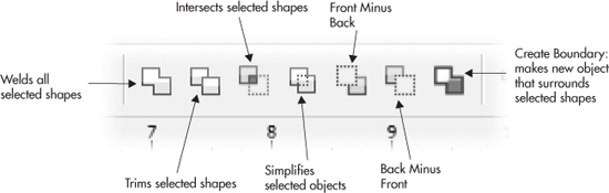
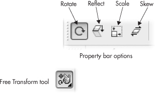
CorelDRAW X5’s property bar provides shaping command buttons that enable you to shape selected objects instantly. These property bar options become available only while at least two objects are selected—and they make shaping commands available whether or not the objects are positioned to overlap. Property bar shaping buttons are shown here:
TIP
When you use property bar shaping buttons, shapes are subtracted, added, and so on, but the original objects—except when you use Create Boundary—go away. To keep your original objects, use the Shaping docker, which offers options to specify that the source object (the one performing the operation—the “scissors”) and/or target object (the object receiving the operation—the “paper”) should remain after shaping.
TIP
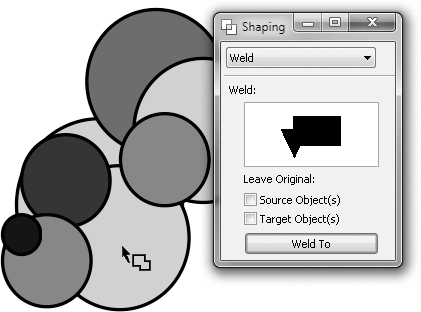
When using the Shaping docker and the Weld and Intersect operations, you have an additional helper: the Intersect With or the Weld To button (shown next) at the bottom. When only one object is selected, naturally it’s hard for CorelDRAW to perform these operations. The idea behind this option is that if you have several objects nestled together (making a target object hard to select), you click the Weld To or the Intersect With button, your cursor changes to a unique shape, and you then click the desired target object to complete the operation.
Boolean Shaping
The mathematical term for what is called “shaping” is Boolean operation. It was named after the 19th century mathematician George Boole, who invented a logic system in algebra for describing certain functions in plain English terms, such as “show me A and B together,” where A and B are geometric shapes. Other shaping operations when translated to these logical statements include “and,” “not,” “or,” and so on. The statement “show me A but not B” can describe the function of the CorelDRAW Back Minus Front shaping operation, as another example. This is the basis for the operation CorelDRAW performs when you use one shape as a target and a different one for the source in a shape operation.
Now that you know where to find the buttons to launch these commands quickly, it’s time to examine what you can do with them. The following section explains the results of applying each command to at least two selected objects:
• Weld The Weld command creates a new shape based on the outline shape of two (or more) objects whether they overlap or not, as shown here. You can specify via the Shaping docker whether the original shapes remain on the page.
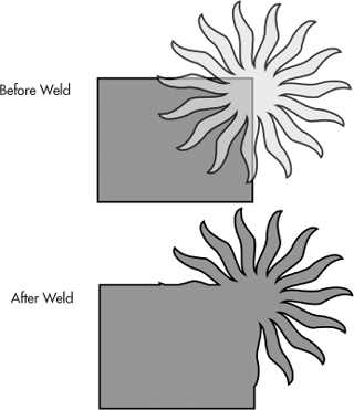
This illustration shows a polygonal, sun-like shape with partial transparency applied to better show the order of objects on the page: the rectangle is behind the sun shape. Not only did the Weld operation create a single object from the two, but it also gave the result object the color of the bottom object. The important thing to know when welding objects is:
• If you marquee-select two objects for the Weld operation, the bottom object’s color is the resulting object color.
• If you select two or more objects one at a time with the Pick tool (by SHIFT-clicking), the last object you choose—regardless of whether it is on top or bottom in the stack of objects on a layer—contains the fill color that will be the result color in the welded object.
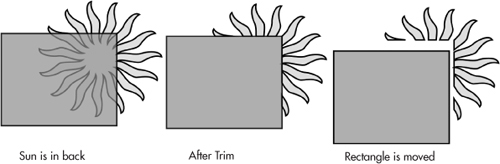
• Trim The Trim command removes any overlapping areas of the object in front from the object(s) in back when marquee-selection is used, as shown next—the rectangle in front is partially transparent to make the effect more obvious. The original objects are automatically deleted, and no color change takes place (the back object does not inherit the front object’s color, transparency, or any other trait). If you select the objects one by one (click, then SHIFT-click), the second object is trimmed.
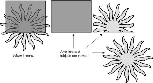
• Intersect The Intersect operation creates a new object based on the overlapping areas of two or more objects. The original objects remain on the page, and the result is not obvious because the new object is in the same position as the overlapping parts of the original objects. In the following figure, the sun shape was on the bottom, and the resulting shape takes on the color of the bottom object, because marquee-selection was used. Intersect is a great operation for creating difficult crops of complex objects. The new sun shape would make a nice logo for a tanning salon!
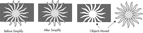
• Simplify The Simplify command removes all hidden areas of objects that “underlap” foreground objects, as the example shows here. This command is great for uncomplicating an intricate drawing, and it can also make a design that otherwise might not print to PostScript correctly, print just fine. As you can see at middle, there is no apparent change to this simple design after the Simplify command is applied, but at right, you can see that when the objects are moved, overlapping areas of the sun in back have been erased, similar but not identical to the Trim and the Back Minus Front operations. Different order and arrangements of objects will result in slightly different results.
• Front Minus Back When two or more shapes are selected, applying the Front Minus Back command removes the hidden area of the object in back from the shape in front. When more than two shapes are selected, it removes all portions where the shapes in back are overlapped by the object in front, leaving only the object in front remaining, as shown here:
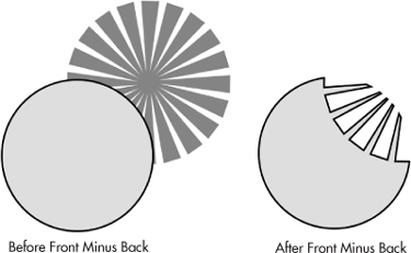
Front Minus Back is a trim operation, “A but not B” in Boolean terminology, and the advantage to using this operation to trim objects is that it removes the guesswork of, “Gosh, what’s the order of the objects in this design?” Front Minus Back is an unambiguous, straightforward trim operation.
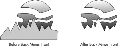
• Back Minus Front This shaping command works in reverse of Front Minus Back. While at least two shapes are selected, applying the Back Minus Front command removes the portions of the shape layered in front from the shape in back. When more than two shapes are selected, it will remove all portions where the shapes in front overlap the shape in back, leaving only the shape in back remaining, as shown here:
• Create Boundary This is similar to the Weld operation, except it leaves the target objects on the page. Also, if there are empty spaces between objects, Create Boundary ignores them when making the combined single object. Here is an example of several objects selected and the resulting shape. By default, the new object has no fill and is ordered on top of the target objects. Just click a foreground color on the color strip, and the new object will become immediately apparent.

NOTE
You can use shaping operations on bitmaps. See Chapter 24 on how to create invaluable cropping effects on your photos using shaping operations and other techniques.
Using the Shaping Docker
Under the Arrange menu, you’ll find all the shaping commands. Also, the Shaping command is on this menu, which opens the Shaping docker in the workspace. As with all dockers, you can detach (undock) this palette so it floats near your work (demanding fewer “mouse miles”), and this docker offers more options than when you use the shaping operations from the property bar. Because of their operation, Simplify, Front Minus Back, and Back Minus Front only have an Apply button, and Create Boundary has Place Behind Selected and Leave Original check boxes.
The first three shaping commands in the selector are applied in slightly different ways from the others. To Weld, Trim, or Intersect, you must have at least one object selected and another unselected (but still in view) for the commands to be available. Once Weld, Trim, or Intersect is selected, the docker will display available options, shown here. Clicking the docker command button begins the action.
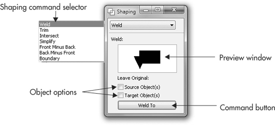
The preview window on the docker doesn’t actually change; it’s an illustration that shows the result of using each operation. The Object options check boxes are what you use to set what object, if any, remains after an operation. Leave Original is equivalent to “make a copy so I don’t lose my originals,” and the options are as follows:
• Source Object(s) When this option is selected, the object you selected before the shaping operation remains after the command has been applied.
• Target Object(s) With this option selected, the object you Trim, Weld to, or Intersect with remains after the command has been applied.
Let’s give this docker a spin. First, create two shapes; the Rectangle tool is fine to make shapes you won’t need later, so they’re expendable in this example:
1. If you haven’t already done so, create the objects on which you want to base your new shape, and position them in such a way that the shape created by their overlapping portions represents your new shape.
2. Select one of these overlapping objects, and open the Shaping docker by choosing Window | Dockers | Shaping.
3. Choose Weld, Trim, or Intersect from the selector at the top of the docker.
4. Choose which original object(s) you want to remain after the command has been applied by clicking Source Object(s) and/or Target Object(s), and then click the command button at the bottom of the docker to apply the command. Notice your cursor has changed to one of three targeting cursors, depending on your shaping operation.
5. Click the object you want your selected object to Trim, Weld to, or Intersect with. Your new shape is immediately created based on the overlapping area of your existing objects.
TIP
The outline and fill properties of newly shaped objects are determined by the properties of the target object.
Choosing Simplify, Front Minus Back, or Back Minus Front requires that at least two objects are selected. If only one object is selected, you’ll get an attention box politely telling you so and asking if you’d like to try again. With any of these commands, the shaping is applied when you click the Apply button in the Shaping docker.
Working Examples of Object Shaping
If you’ve seen some stunning CorelDRAW creations and said to yourself, “Wow, that must’ve taken that artist ages to do all that work,” nope, it probably didn’t: the artist put object shaping to work. The following shows just three of thousands of creative possibilities for shaping operations; these are just a few examples to kindle your efforts.
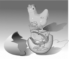
Here is an example problem and a solution using the Trim operation. The chicken came first, then the need to make the chicken drawing look as though it’s peeking through the broken eggshell. The chicken drawing is composed of several grouped sub-objects; the Trim operation trims all objects in a group. Walk through the next set of steps to see how the Trim operation solves a lot of the manual effort of editing dozens of objects to visually integrate the chicken drawing into the scene. All the shapes needed to perform the Trim operation have been added for you; just focus on how to use the Trim operation.
 Trimming a Chicken
1. Open Chicken.cdr. The goal is to place the toy chicken drawing so that it looks as though it’s peeking out of the half-shell at right.
2. With the Pick tool, drag the chicken group’s objects, and position them so the lower half of the chicken is over the eggshell.
3. Choose Arrange | Shaping | Shaping to display the Shaping docker.
4. Select the dashed outline shape. If you were designing this composition from scratch, the Pen tool would be ideal for drawing such a shape. The blue dashed outline is only to call attention to the object in this example—the shape can be any outline color or style.
5. Choose Trim from the drop-down list. Put a check in the Target Object(s) check box so a copy of the whole chicken remains in the drawing. Why spoil a perfectly good drawing?
6. Because only one object is selected, you now click Trim on the Shaping docker, and the docker queries you on what you want trimmed.
7. With the special cursor, click over the chicken.
8. With the Pick tool, move the lower (whole) chicken out of the way to see the results. Try a click-drag over the wing.
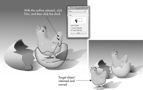
Figure 11-1 shows a combination Weld and then a Trim, although Back Minus Front would work as the second step, too. The problem in this composition is that a specific font is needed in stencil style, but the artist doesn’t have such a typeface. So Arial is first used, and then:
1. Draw several rectangles over areas that need to be removed from the text to create the stencil effect.
2. Create duplicates of one narrow rectangle by using the drop-a-copy technique: drag a rectangle to a new location, and then tap both mouse buttons before releasing both buttons. Doing this keeps consistency between areas to be removed from the text.
3. After all the rectangles are in position, marquee-select the rectangles, and then use the Weld command to make a single object out of the rectangles.
4. Remove the single shape from the text by using it as the Source object in the Trim operation. The text is trimmed.
5. Finally, use Effects | Add Perspective to make the text appear as though it’s on the 3D crate. The text probably could use some rotation, but you get the idea.
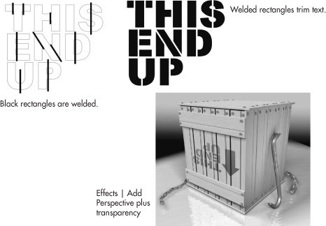
FIGURE 11-1 Weld and then Trim are used to make a stencil treatment out of the text.
Figure 11-2 uses Back Minus Front, Weld, and an Arrow shape (covered in Chapter 16) to create a complex-looking design for a corporate logo. First, a circle is drawn using the Ellipse tool in combination with holding CTRL (to constrain ovals to perfect circles). Then, to put a smaller circle centered inside the first, you hold SHIFT, drag the original circle’s corner-bounding box handle toward the center, then right-click before releasing the left mouse button to create a scaled duplicate. Back Minus Front is chosen on the Shaping docker with both objects selected; click Apply and you have a perfect doughnut object. The Arrow shapes come in all four directions on the property bar; four arrows are dragged to create with this tool, they’re arranged, and then all four arrows are selected. The Weld operation is chosen on the Shaping docker. Then with the large arrow cursor, the doughnut is clicked to indicate it’s the target object. This could be the end of the story, but in only a few clicks, the resulting shape can be extruded and rotated. See Chapter 19 for the complete details on object extrusion—3D is yours to experiment with within CorelDRAW.
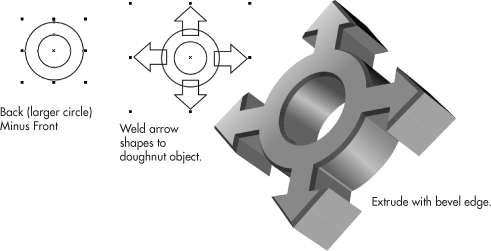
FIGURE 11-2 Complex illustrations don’t need to take a lot of time. Get to know the Shape tools, and what you envision is only a few clicks away.
Fillet/Scallop/Chamfer
The Fillet/Scallop/Chamfer docker can be displayed by choosing it from Window | Dockers, and with it, you have your choice of truncating sharp corners of an object you draw. This docker will not alter a curved path segment: a shape that consists of straight paths is the best to use with this feature; objects with a combination of curved and straight segments will only be affected along the convergence of two straight path segments.
When Fillet/Scallop/Chamfer evaluates sharp direction changes along a path, it “rounds off” the point of a convex area toward the inside of the path and increases concave areas. This is a terrific feature for quickly building elegant objects such as furniture pieces, machine parts, and nice ornaments for desktop publishing documents. When you enter a positive value in the Radius field (or use the elevator buttons on the docker), you see a faint outline preview in your document, and then you click Apply when you’re happy with the preview. Fillet/Scallop/Chamfer is a destructive operation, unlike the shaping operations, so if you want to keep your original object, duplicate it before using this docker.
• Fillet Rounds the corners of an object
• Scallop Trims a semicircle from the corner of an object
• Chamfer Lops a straight angle off a corner at an angle perpendicular to the interior angle of the corner
Figure 11-3 shows the effects of the Fillet/Scallop/Chamfer docker on the same zigzag object created with a single-click and the Pen tool. Because the Radius of this trimming effect is measured in page units, it’s usually a good idea to keep rulers visible in your document, and to refer to them to achieve the exact degree of corner truncation you need.
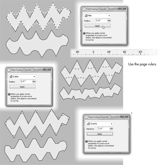
FIGURE 11-3 Use the Fillet/Scallop/Chamfer docker to take the corners off an object with intricacy and classic style.
PowerClips
CorelDRAW PowerClips change the appearance of a shape by hiding certain areas of its exterior with a different shape. This, unlike other reshaping operations, is completely nondestructive, and the clipping object can release the inner clipped object(s) at any time. Consider the usefulness of PowerClips: You can hide most of an object from view and put other objects behind the PowerClip. You can play a dozen possible scenarios for the composition you have on a page, and never commit to any of them, unlike with trimming an object.
To give you an idea of the creative power of PowerClips, follow these steps with a document whose objects have already been created for you. The assignment is to put a design on the bottom of a flower vase, stencil-style, so parts of the vase’s original color still show through in different regions. It’s not hard work when you’re familiar with PowerClips.
PowerClipping a Design onto an Object
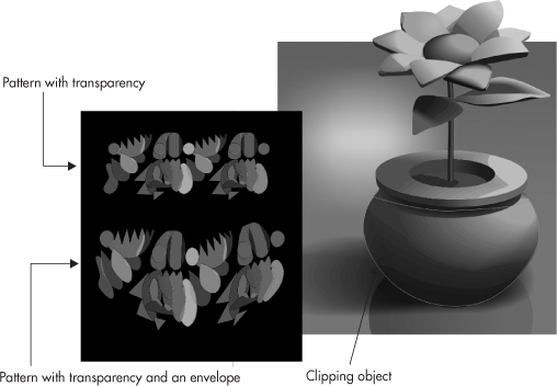
1. Open Flower and Vase.cdr. To the left you’ll see a grouped pattern with transparency. Below it is the same pattern with an envelope applied to make the pattern look bulged, as it would when viewed on the surface of a round shape such as the vase drawing here. At right, over the vase, is a thin yellow outline shape that is a fairly accurate trace over the vase. This will be your PowerClip shape for the pattern—it will hide all shapes outside of it. If you’d like to use the Envelope tool to experiment with the non-enveloped grouped pattern, Chapter 20 provides the complete documentation on this feature.
2. Select the bottom pattern with the Pick tool, and then drag it over so it’s on top of the yellow outline object, making certain that all parts of the pattern overlap the outline. You don’t want gaps in the pattern as it’s displayed on the vase.
3. Choose Effects | PowerClip | Place Inside Container.
4. A huge arrow becomes your cursor. Click the cursor over the yellow outline, and the pattern scoots inside the container object.
5. The container object is now selected. Right-click over the No Fill color well on the Color Palette to remove the outline, or alternatively, choose None for the Outline Width from the drop-down list on the property bar. See Figure 11-4.
Although the preceding example shows how to mask the exterior of a group of shapes, a PowerClip container can also have an outline width, color, and a fill. In any case, the nondestructive property of PowerClips will serve you in a number of design situations.
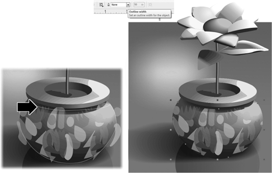
FIGURE 11-4 Let empty areas in patterns and other complex drawings show through a PowerClip object.
Occasionally, an object “inside” the PowerClip container might not be aligned perfectly relative to your overall composition. You also might like to do a little editing to the contained object(s). This is not directly done on the page. Here are the editing options for a PowerClipped object:
• To reveal the object for editing or repositioning relative to the PowerClip object, right-click over the object, and then choose Edit Contents from the pop-up menu. A blue outline indicates the size and position of the PowerClip container. When you’re done editing, right-click and then choose Finish Editing This Level.
• To undo the PowerClip effect, you can press CTRL+Z right after making the command, or right-click over the PowerClip object, and then choose Extract Contents. Your PowerClipped object(s) and the container are restored to their original condition, but not always to their original position on the page.
• To quickly reposition the contents of a PowerClip container, right-click and then choose Lock Contents To PowerClip. This is a toggle on and off state: when it’s unlocked, you can reposition the container by dragging with the Pick tool. You can also scale and rotate the container without affecting the contents. When it’s locked, the contents travel with the container objects wherever you drag.
The Knife Tool
The Knife tool functions like a knife you’d use in the real world—except you can run with it and it requires no sharpening— and feels quite natural to use. You begin by hovering over an object area where you want to begin the cut, your cursor changes its appearance to signify it is ready, and then you click-drag to the end of the cut, the other side of the object. The result is two separate closed objects. As with many of CorelDRAW’s tools, SHIFT and CTRL can be used as modifier keys as you work with the knife, and in the case of the Knife tool, these modifier keys add precision to your cuts. You’ll find the Knife tool in the toolbox grouped together with the Crop, Eraser, and Virtual Segment Delete tools.

Types of Cuts with the Knife Tool
There are three ways to cut a shape with the Knife tool, and each one requires a different keyboard/mouse technique.
• Straight cuts Suppose you want to slice an object into two separate shapes as you’d do with a workshop saw. To produce straight lines on sides of both objects, you aim the cursor on the near side of the object, hover until you see it change from an angled cursor to an upright one, click, release the mouse button, and then click the far side of the object, as shown in Figure 11-5.
• Freeform cuts This technique can be used, for example, to quickly create an illustration of a sheet of paper roughly torn in half. You hover the cursor until it turns upright, click-hold the near side of the object, and then drag until you reach the far side of the shape, as shown in Figure 11-6.
• Bézier cuts If you need to guide the Knife tool to make smooth jigsaw-like cuts, you hold SHIFT, and then click-drag points, beginning at the near side and completing the cut at the far side, as shown in Figure 11-7. Notice that not only do the cut result objects inherit the original shape’s fill, but this applies to all types of fills, including gradients. The shapes in this figure each have a gradient start and end point inherited from the original shape, and if you choose the Interactive gradient tool, you can adjust each object’s gradient directly and come up with a visually interesting jigsaw puzzle composition or other complex drawing.
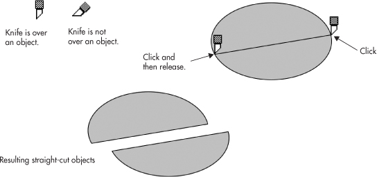
FIGURE 11-5 Click, release, then click to create a Knife tool straight cut.
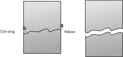
FIGURE 11-6 Click-drag to create a freeform cut.
Naturally, if you have a specific cut in mind, you’ll get the best results using the shaping operations, and you cannot edit a Bézier cut’s path as you make the cut, but the Knife tool does provide fast and easy results.
TIP
If you hold both SHIFT and CTRL while click-dragging to make a Bézier cut, doing so constrains the direction of the path to 15-degree increments for more predictable results in making the edge of the cut.
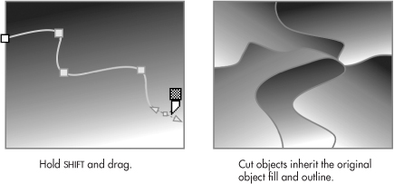
FIGURE 11-7 Bézier cuts guide the Knife tool with the precision of using a digitizing tablet and stylus.
Setting Knife Tool Behavior
Using the Knife tool results in just what you’d expect—several objects out of a single one. However, you do have options, the two property bar options shown here. Each of these options toggles on and off to suit a specific cutting requirement.

• Auto-Close On Cut mode This option, on by default, sets the Knife tool to create closed-path objects following any style of Knife tool cutting. If you turn this option off, the Knife tool divides an object into two open paths and removes any fill. This can be a useful mode for breaking a closed shape into open paths. To use this option, don’t drag with the Knife tool, but instead click a near point and a far point.
• Leave As One Object mode This option is active by default; if you disable it, the Knife tool cuts an object, but the result is a combined path—in other words, you don’t get two separate objects. This option is useful on occasions (for creating characters in typefaces, for example), but it probably would not be an everyday mode of operation for your work.
TIP
Both the Eraser and Knife tools can be used on imported bitmaps; you can perform a little photo retouching with these tools exactly as you would with vector objects. The only restriction is that a bitmap (BMP, TIFF, JPEG, and so on) has to actually be imported to the document; if it is externally linked, the tools can’t be used on this reference to bitmap images.
Using the Eraser Tool
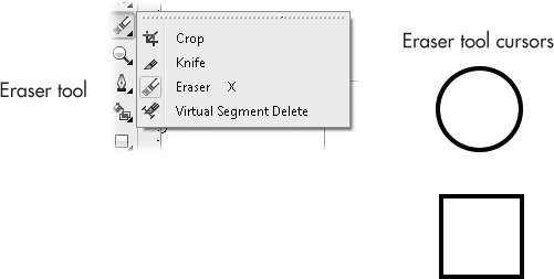
The Eraser tool, shown next, completely removes areas of selected objects you click-drag over—just like a real art eraser, but without the stubble landing in your lap. The Eraser tool comes in two different shapes, and you can define the size by using the property bar. You’ll find it in the toolbox grouped with the Knife, Virtual Segment Delete, and Crop tools.
Working with Eraser Operations
With this tool, you can remove portions of shapes in four ways:
• Double-clicking When you double-click a selected shape, you remove an area that is the shape of the cursor. Therefore, if you double-click a lot with the circular cursor chosen, you can quickly design a slice of Swiss cheese.
• Single-click two points If you single-click, move your cursor, and then click a second time, the Eraser tool erases a straight line through the selected object.
• Click-drag This is the most common method of erasing, and the results are totally predictable. If you click-drag, you erase the area you’ve dragged over on a selected object.
NOTE
Grouped objects do not qualify for use with the Eraser tool. However, if you CTRL-click an object in a group to temporarily isolate it, you can indeed erase part of the object.
• Hovering and pressing TAB This technique creates several connected straight-line segments, and after you get the hang of it, it will feel like you’re painting with an eraser, and you’ll be able to quickly produce phenomenally expressive and complex drawings.
Walk through the following tutorial to see the power of this hover-TAB erasing technique and to make it your own.
Power Erasing
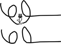
1. Open Don’t Litter.cdr, an incomplete international symbol that tells the audience, “Put refuse in the appropriate place; don’t be a pig.” The orange areas are guides for you; they’re locked on the Guides layer.
2. Select the main object. Choose the Eraser tool and then set the nib style to rectangular by clicking the default nib style (the circle) on the property bar. For this example, set the nib size to about .18″.
3. Single-click at the top left of the wastebasket guide. Move your cursor over to the bottom left of the wastebasket guide, but don’t click. Notice as you move the Eraser tool that a path preview follows the cursor.
4. Press TAB, but don’t click your mouse button. Notice that a new erasure appears between the first single-click point and the point where you pressed TAB.
5. To define a third point, move your cursor to a new point (without clicking the mouse button) and then press TAB again. A third point is defined, and the path between the second and third points is erased. To stop using the Eraser tool, click at the end to halt CorelDRAW from connecting the points you click with a line between them.
6. When you’re done with the wastebasket, set the nib style to round, and then add limbs to the thoughtful international guy. Use the TAB technique, for example, to extend a forearm from the guy’s shoulder, and once this segment has been erased, double-click where you think his hand would be to extend the erasure. Single-click to end an erasure. Figure 11-8 shows the work in progress.
TIP
Each time the Eraser tool cursor is clicked to erase portions of your object, CorelDRAW considers the action as a unique and separate erase session. This means that Eraser tool actions can be reversed using the Undo command (CTRL+Z) in steps, depending on which erase technique was used. While using the single-click technique, an Undo command is needed to reverse each erase point. During a continuous erase using the click-drag action, a single Undo command reverses each continuous erasing session.
Setting Eraser Tool Properties
The width and shape of the Eraser tool are set using property bar options, as shown next. The complexity of the removed shape, the number of path segments, and the connecting nodes created during an erase session can also be controlled. These properties significantly affect the shape of erased object areas.

FIGURE 11-8 Press TAB to define intermediate points between your first and last erase-path points to create connected, straight-line erasures.
TIP
As with most of the toolbox tools, you can get to the options for the Eraser tool in Options by double-clicking the button on the toolbox.
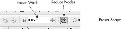
Eraser Width
Width can be set between 0.001 and 100.0 inches either by entering values in the property bar combo box or by pressing the UP and DOWN ARROW keys on your keyboard to increase or decrease the size. Naturally, you might never need a 100-inch eraser; it makes more sense to use the shaping operations—but you do have this latitude.
TIP
Use the keyboard to change the cursor size while you erase. Press the UP ARROW and/or DOWN ARROW key while click-dragging, and the result can be a tapered brush, as shown here. After you release the mouse button, the Eraser tool resets to its original size, so you don’t have to worry about starting out a new erase stroke with a yard-wide tip!

Reduce Nodes Mode
Erasing continuous paths removes portions of objects to create new sides that are made up of normal vector path segments and nodes. How closely the new edges follow your erase path is determined by the number and properties of the nodes that are produced. The more nodes, the more complex and accurate the erased shape will be. While selected, the Reduce Nodes option affects the complexity of the resulting erased shape when erasing in continuous freehand-style paths.
Adding nodes to an already-complicated object, however, can create an overly complex object, something that can slow you down—the excess nodes don’t contribute to the artwork and may result in inconvenient screen redraws of effects you might apply. The Reduce Nodes option lets you reduce the complexity of erased area shapes at the price of what’s usually trivial inaccuracy. To activate the Reduce Nodes option, click the button to the depressed position (the default), or deactivate it by clicking it to the undepressed state.
TIP
The Eraser tool’s Reduce Nodes settings are set according to the Freehand smoothing default setting used by the Freehand and Bézier tools, which can be set between 0 and 100 percent (the default is 50). To set this option, double-click the Eraser tool button on the toolbox. By default, it’s enabled.
Using the Virtual Segment Delete Tool
The Virtual Segment Delete tool is used to delete specific portions of objects, specifically, overlapping areas. Additionally, this tool removes portions of an object’s path where they intersect paths of other overlapping objects.
To use this tool to delete path segments where an object intersects itself, use these quick steps:
1. With the Freehand tool, draw a path that loops around and crosses itself.
2. Hold your cursor over the segment to delete—you don’t need to have the objects selected to use this tool. You’ll notice the cursor becomes upright when an eligible segment is hovered over (shown at top here).
3. Click the cursor directly on the segment you want to delete. The segment you targeted is immediately deleted.
After deleting portions of a path with this tool, what remains is either an open curve with just one path, or a compound curve with two or more subpaths. For example, if the object you’re deleting segments from is a closed path, deleting one segment will result in an open curve. Deleting a segment from a rectangle, ellipse, or polygon object will convert the resulting shape to curves and remove the dynamic object properties. To delete segments that are hidden behind an overlapping object, temporarily set its Fill to None.
TIP
If the object you are deleting segments from is a compound path (an object composed of more than one open or closed path), the Virtual Segment Delete tool will work best if the object is first broken into individual curves using the Break Apart (CTRL+K) command.
Cropping an Illustration
The Crop tool, located in the group with the Knife and the Eraser tools, brings a bitmap effect to vector drawing. If you have experience with Corel PHOTO-PAINT or another photo-editing program, you already are familiar with a crop tool: you select an area within a photo, perform a command such as clicking inside the crop area, and the area outside the crop is deleted and the image is resized.
The Crop tool in CorelDRAW behaves exactly like an image editor’s crop tool. Objects do not have to be grouped; you just drag a rectangle around the area of your design you want cropped, double-click inside the proposed crop area, and all object areas outside the crop box are deleted. In Figure 11-9 at left you can see two objects: the goal is to leave only the comedy mask and to get rid of the tragedy mask. In the middle the Crop tool is dragged around the desired area, which then is double-clicked. At right you can see two separate objects: the cropped gray background and the cropped mask. This is a powerful and potentially very destructive tool, but fortunately you can work with the proposed crop box before cropping. You can drag a corner crop box handle before cropping to proportionately resize the crop; dragging a middle handle disproportionately resizes the crop area.
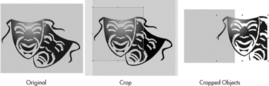
FIGURE 11-9 The Crop tool removes all areas of every object that lies outside the crop box.
Additionally, once you’ve made a proposed crop, clicking, then clicking again inside the box puts the box in rotation mode, and you can actually crop a diamond shape. If you want to cancel a crop operation, press ESC and the crop box goes away.
Using the Smudge Brush
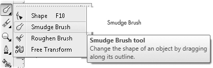
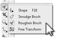
The Smudge brush tool is yet another paint tool in a drawing program: not only is this tool a lot of fun to use, but you can also dramatically alter shapes in a natural, painterly fashion whose results would take hours using any other method. You move areas of a vector object by dragging from a starting point inside the object, dragging outward, or by starting outside and dragging inside the object. The result is a smear, but with all the crispness of a vector design. You’ll find the Smudge brush, shown next, in the toolbox, grouped with the Roughen brush, the Shape, and Free Transform tools.
Applying Smudge to Shapes
Using the Smudge brush, you can alter the outline shapes of open or closed paths by click-dragging across the outline path, in either an outward direction (to add a bulge) or an inward direction (to create a pucker). As you drag, the path is altered according to your drag action and to the shape settings of the Smudge brush cursor. Figure 11-10 shows a creative example of using the Smudge brush: the cartoon head has long, spiky hair now; the editing took less than 5 seconds, and the resulting path can be edited for refining by using the Shape tool and other CorelDRAW features.
TIP
If you’re trying to smudge shapes that have been applied with an effect (Envelope, Blend, Contour, Distortion, Extrude, or Drop Shadow), you’ll first need to break apart the effect. If the shape is part of a group, you’ll need to ungroup it first (CTRL+U). Smudging cannot be applied to bitmaps.
Choosing Smudge Brush Property Bar Options
In case you haven’t noticed, the Smudge brush works quite differently from other tools. You can control how the Smudge brush effect is applied by varying tool properties such as the tilt, angle, and size of the nib; or by adjusting how quickly the effect diminishes; or by using optional pressure stylus settings.
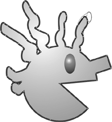
FIGURE 11-10 The Smudge brush treats vector objects as though they’re made of liquid.
While the Smudge brush is selected, the property bar offers these options for controlling the shape and condition of your Smudge brush cursor:
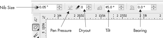
Changing each of these options has the following effect:
• Nib Size Nib Size can be set between 0.02 and 2.0″; the default is 0.1″.
• Pen Pressure If you have a digitizing tablet and stylus that supports pressure, choose this option to have the Smudge brush react to pressure you apply while increasing the width of the nib.
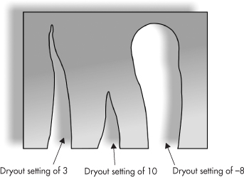
• Dryout This option sets a rate for the effect of gradually reducing the width of a smudge according to the speed of your click-drag action and can be set between –10 and 10. Higher values cause your smudge to be reduced in width more quickly (as shown next), while a setting of 0 deactivates the Dryout effect. Interestingly, negative Dryout values make your stroke begin small and eventually widen as you click-drag.
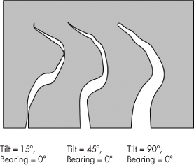
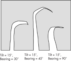
• Tilt The Tilt value controls the elliptical shape of the Smudge tool nib. Tilt is measured in degrees set between 15° (a flat-shaped nib) and 90° (a circular-shaped nib), as shown next. Tilt and Bearing values (discussed next) work in combination with each other to control the smudge nib shape.
• Bearing Bearing lets you set the angle of the cursor in circular degrees (0 to 359°). The effects of changing Bearing are most noticeable at lower Tilt values—such as 15°, as shown here. It’s the rotational angle of a non-circular tip.
Using the Free Transform Tool
The Free Transform tool, located in the same group as the Smudge brush, the Shape tool, and the Roughen brush, is your one-stop shop for performing rotations, skews, and other object transformations using an onscreen guide.
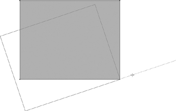
Unlike with the Pick tool for object transformations, the Free Transform tool has a handle by which you steer and have precise control over the object you manipulate. To use the tool, you choose it from the toolbox, choose a transformation type on the property bar, and then with the object selected, you click-drag on a control point (or any object node) to set the center of the transformation; dragging reveals a handle that also serves as a visual indicator of the amount of transformation you’re creating. This preview of the transformation is in effect until you release the mouse button. As you can see in this illustration, it’s obvious the rectangle is being rotated, where the center of rotation is, and the extent of the rotation before the transformation is actually made.
The Roughen Brush
To add a touch of character and imperfection to ultra-precise objects, you have the new Roughen brush in the group with the Smudge brush, shown here:
The Roughen brush alters the course of an outline path on an object, and depending on the setting you use on the property bar, you can achieve effects that range from lightning bolts, to really gnarly lines, to zigzag patterns, just by dragging on the edge of a shape. The options you have when using the Roughen brush can be seen here on the property bar; they’re similar to those of the Smudge brush:
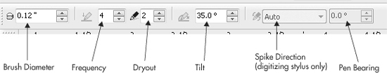
• Brush Diameter This sets the size of the Roughen brush. It’s usually a good idea to scale the nib in proportion to the selected object you want to roughen. By default the scale of the nib is measured in inches.
• Pressure Sensitivity If you use a digitizing tablet and stylus that responds to pressure, this option can be used to vary the nib width as you drag over object areas. The option is dimmed on the property bar if CorelDRAW doesn’t detect a digitizing tablet hooked up to your system.
• Frequency You’ll see that the Roughen brush creates irregularity on an object edge that is similar to the peaks and valleys of a mountain range—it varies the object outline in an “in and out” fashion. At low Frequency values, the roughened object outline will feature large, varying areas. At high Frequency settings, you’ll attain a zigzag effect. The range of Frequency is from 1 to 10 (10 produces zigzags).
• Dryout Like the Smudge brush, the Roughen brush can “dry out” at the end of a stroke you drag with the cursor. The range of dryout effect is from –10 (the stroke tapers in the opposite direction in which you click-drag) to 10 (the stroke tapers and fades). At 0, the stroke remains consistent. The greater the Dryout setting, negative or positive, the more natural a roughened appearance you can achieve.
• Tilt This option measures your stroke with the Roughen brush perpendicular to the edge on which you stroke. Therefore, if you have an edge that travels straight up and down, at a 90° setting you’ll achieve very little effect. In your experiments with this tool, try 45°, an overall good setting for all angles of edges on most objects. When you roughen an edge that already has roughening applied, you overwrite the previous distortion of that edge. Figure 11-11 shows two examples of the Roughen brush; at left a small nib is used at a low Frequency, and at right a large nib is used at high Frequency.
TIP
Shapes that have special properties, such as rectangles and ellipses created with the Rectangle and Ellipse tools, need to be simplified using the Arrange | Convert To Curves command (CTRL+Q) before they can be roughened. If you try to use the Roughen brush on such a shape, you’ll get an attention box telling you that the object needs simplifying, but then CorelDRAW will automatically do the operation for you. So if you want to avoid the attention box, press CTRL+Q while a shape is selected, so you can get right down to editing.
This chapter has taken you through several processes by which you can create minor and big-time alterations to just about anything you draw; additionally, many of the operations apply to bitmaps you bring into the workspace. Use the command that best suits the task you have in mind, and use your judgment as to which operation will get you to your goal fastest. Personal computers are productivity enhancers: there’s no need to labor over something when CorelDRAW and your PC can do it for you in less time.
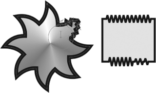
FIGURE 11-11 Use the Roughen brush to achieve object complexity in a fraction of the time needed using other tools.
Now that you have one, or two, or a dozen shapes on your drawing page, it would be nice to mix them up with some honest-to-gosh text: a headline here, a little body copy there. Shapes and words live together, practically no one publishes an image-only website, and Chapter 12, Part IV of this guide gets you into the language of typography and the features in CorelDRAW that make your keyboard a professional communications tool.