
CHAPTER 20 Envelope and Distortion Effects
You’ve probably seen this effect in stores a dozen times: the words “Fresh Fish” shaped in the silhouette of a fish. In CorelDRAW this is called an envelope effect. With it, you can shape words and other objects (and groups of objects) to conform to a different shape. And to add to your creative effects in CorelDRAW, there’s also the Distort tool, a kissing cousin of the envelope effect, which provides much more dramatic reshaping options, and which makes quick work, for example, of reshaping a simple flower petal shape to look more natural and intricate.
Remember when you were a child and played with that putty that came in a plastic egg? This is the theme of this chapter; in it, you’ll learn how to treat apparently solid and stiff objects as though they had the flexibility of putty. In the process, you’ll gather several practical and creative uses for the envelope and distort features…and discover that work can be fun!
What Does an Envelope Do?
In CorelDRAW you can start with a fresh envelope around an object, use presets, copy a shape to use as an envelope of a different shape, and edit the envelope until the object suits your need. Envelopes are nondestructive; your original artwork can be restored at any time. The property bar has a “remove envelope” button when an enveloped object is selected with the Envelope tool. Once an envelope has been defined, you edit the envelope exactly as you would a path—you can drag on segments and nodes, and change the node control points to your heart’s content.
Figure 20-1 demonstrates both the ease and usefulness of the envelope effect. In the top illustration, the artistic text object is enveloped, and the envelope is based on an existing shape seen at right. The bottom illustration shows the envelope control segments and nodes in the process of being edited. It’s true: the CorelDRAW envelope effect is just like playing with silly you-know-what!
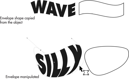
FIGURE 20-1 Use the Envelope tool to create different object looks.
Creating Envelope Effects
When applying envelopes, you can choose from three different methods:
• Shape your envelope from scratch by defining a default envelope and then manually reshaping it.
• Copy an envelope shape based on an object on the drawing page.
• Apply a preset.
Let’s begin working with the first technique.
Using the Envelope Tool and Property Bar
Using the Envelope tool along with the property bar options is the most intuitive way to apply envelopes. You’ll find it in the toolbox grouped with other interactive tools, as shown here:
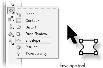
With both the Envelope tool and an object selected, the property bar displays the options shown here:
You’ll get the best results from the envelope effect if you follow a sequence of moves in CorelDRAW. Let’s work through some basic maneuvers using the following steps.
 The Envelope, Please
1. Create or open an object (or group of objects) that you feel would make a good target for the envelope effect, and then choose the Envelope tool from the toolbox. Notice that the property bar shows envelope options. The more intricate the object, the more noticeable the effect will be. In general, don’t choose a rectangular shape to which you want to apply a rectangular envelope; the effect would be more or less redundant.
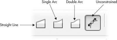
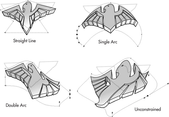
2. Click the mode button resembling a square with one corner higher than the other— the Straight Line mode button—and notice the markers surrounding your object.
3. Drag one of the nodes on your object in any direction. Notice that the direction of movement is constrained, and the shape of your object changes to match the envelope as you release the mouse button.
4. Click the next mode button, resembling a square with one curved side—the Single Arc mode button. Drag any node in any direction, and notice that the object changes, but this time you have some curvature going on with the edges of the envelope and the object(s) inside. The Double Arc mode provides more distortion, most noticeably when you drag a center envelope node instead of one of the four corner bounding nodes.
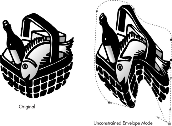
5. Notice that you can drag an envelope node to reshape the object, but the direction handles on either side of the node are fixed and won’t budge. Click the Unconstrained Mode button, the rightmost envelope mode on the property bar. Now try dragging nodes and then their direction handles. The following illustration shows the object group in its original state, and then at right it’s been worked over a little in Unconstrained mode…it looks reminiscent of how your packages occasionally arrive on Mondays, doesn’t it? In all seriousness, however, this is a prime example of the plasticity with which you can reshape objects through the envelope feature. Nothing is hard and fixed in a CorelDRAW drawing and no changes are permanent.
You’ve applied a basic envelope effect to your object, but the inherent shape of the object remains intact. Clicking the Clear Envelope button in the property bar removes the envelope, returning everything to normal.
CAUTION
There is a limit, particularly with grouped objects in an envelope, to how much you can reshape before the paths that make up an object begin to self-intersect. This is usually an unwanted effect, so the remedies are to take it easy on the extent of the envelope, to ungroup the group and apply similar envelope effects to individual objects, or to use the distort effect, shown later in this chapter.
Using the Envelope Docker
The Envelope docker provides an alternative to using the interactive method. This docker enables you to select options before they are actually applied. To open the Envelope docker, shown in Figure 20-2, choose Effects | Envelope, or press CTRL+F7.
TIP
The main difference between using the Envelope tool and the Envelope docker is that the docker is more visual—you have a good view of presets, but the set of editing tools on the docker is not comprehensive. The docker might be for a less experienced Corellian to use, while using the property bar with the Envelope tool and the Shape tool after an envelope has been created is the sport of designers who want hands-on, low-level control over the effect.
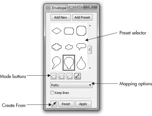
FIGURE 20-2 The Envelope docker lets you select options before they are applied.
To apply the effect using the Envelope docker, follow these steps.
Creating Envelopes via the Docker
1. Create or import an object, select it, and then open the Envelope docker (CTRL+F7).
2. Click the Add Preset button; notice how the preset selector window fills with thumbnails of the presets. Choose one (try the heart shape) by clicking the thumbnail; you can see a dashed outline preview surrounding your object on the page. You could click Apply to apply the preset, but don’t do that right now.
3. In any direction, drag a node on the envelope bounding box surrounding your object. Depending on the preset shape, you can also drag a direction handle—straight line presets don’t have node direction handles, but curved objects such as the heart do. Notice that the Apply button is now dimmed; when you edit a preset bounding box, CorelDRAW assumes you’ve accepted the preset shape, so there’s no fussing with the Apply button.
4. The Reset button does not reset the preset object; instead, it calls the last-used preset. If you want to clear the envelope now, notice that the property bar features the Clear Envelope button and other options as long as the docker is onscreen.
Envelope Tool Cursor States
By following either of the previous tutorials, you’ll have noticed your cursor changes its look, as shown next. These cursor states are visual signals that you’re about to edit the envelope in different ways, depending on what part of the envelope your cursor is over.
While you’re shaping your envelope, the cursor becomes active. But when your cursor is held over envelope nodes or segments (the dotted lines surrounding your envelope object), the Shape tool takes over, letting you change the position and properties of the nodes and segments by click-dragging (see Figure 20-3).
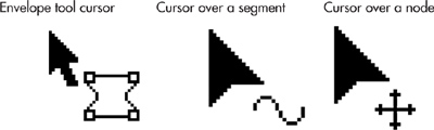
You don’t necessarily have to reach for the Envelope tool to edit an enveloped object. You can use the Shape tool, and as you can see in the previous illustration, the Envelope tool’s cursor looks exactly like the Shape tool’s default cursor when it’s over an envelope segment or node. When you’re repositioning or changing the property of envelope nodes, your cursor looks like the Shape tool’s reposition cursor—indicating the node can be moved, and that you can use the property bar’s envelope node tools to convert, for example, a smooth envelope node to a cusp node. When held over an envelope segment, your cursor will change into the Shape tool with a tiny curved-line symbol, indicating the segment can be edited. Using either cursor immediately alters your envelope, but editing envelope curves can be done only while the Unconstrained Envelope mode is selected.
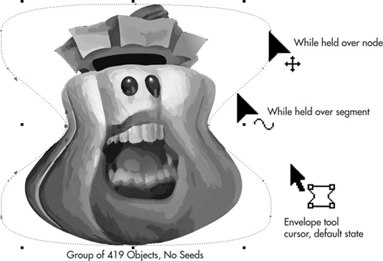
FIGURE 20-3 The Envelope tool has these three cursor states.
TIP
For speedy envelope editing, use the Pick tool to double-click any object that has an envelope. The enveloped object is immediately available for editing, and surprise, the Pick tool is now the Envelope tool. A single click with the Shape tool also opens an enveloped object for editing.
Choosing an Envelope Mode
The envelope mode you choose has no initial effect on the envelope you apply to an object; however, as you begin to move envelope nodes, the mode of the envelope offers features or limitations, depending on what it is you want to accomplish. Depending on the mode, corner and segment nodes take on different properties, which result in different capabilities to edit the envelope, as seen here:
TIP
At any time while editing an envelope, you can change its mode just by clicking a button on the property bar. This capability gives you control over the overall shape you’re trying to create. Any previous mode limitation is inherited with existing nodes, but nodes you’ve not changed inherit the new node property. For example, suppose your envelope is in Double Arc mode, and you drag a node to make a swooping arc, and then you click the Straight Line mode button on the property bar. The arc remains an arc, but all the other nodes can now only be edited as connectors to straight lines.
These modes have the following effects during shaping operations:
• Straight Line This mode (the default) causes envelope segments to be straight lines; in effect, you’re manipulating an eight-point polygon when the envelope is in Straight Line mode. Dragging an envelope node creates a different polygon object, and this mode will serve you well for imitating the shape of a traffic sign, a simple house shape, and other outlines you create with straight line segments. In this case, all node positioning is constrained to vertical and horizontal position changes.
• Single Arc This mode sets the resulting envelope segments to curves, sets side nodes to smooth nodes, and sets corner nodes to cusp nodes; you can’t change the angle of the cusp for corner nodes directly, but you do change it when you reposition a side envelope node. When you’re using this mode, dragging corner nodes creates a curved side on the envelope, while side nodes align with the path of the resulting curve. Node movement is constrained to vertical and horizontal movement, while side nodes can be moved independently of corner nodes.
• Double Arc This mode creates the effect of sine-wave-shaped sides. Behind the scenes, corner points become cusp nodes, while side nodes become smooth nodes. However, the curve handles of side nodes remain stationary in relation to the nodes, causing the segments to take on a double-arc shape. The same vertical and horizontal constraint restrictions as with the previous modes apply. Side nodes may be moved independently of corner nodes, but they apply a similar curve effect, as with the Single Arc mode.
• Unconstrained The Unconstrained mode gives you complete control over nodes, segments, and control handles for envelope elements; it’s probably the mode of choice for ambitious enveloping artists. You can position either side or corner nodes as if they were ordinary vector path object nodes. In this mode, the Envelope tool gives you unlimited flexibility (you can severely reshape objects), and nodes can be dragged in any direction to shape the envelope in any way. Unconstrained mode also provides the options to add or delete nodes, change any line segment state to straight or curved, or to change the properties of nodes to Cusp, Smooth, or Symmetrical using property bar buttons for these tasks.
Saving and Applying Envelope Presets
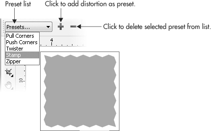
The property bar Preset list (shown in Figure 20-4) contains saved presets and options for applying, adding, and deleting preset envelope objects.
You can add a shape you’ve created as a new envelope object, and delete presets from the list using the Add Preset (+) and Delete Preset (–) buttons. It’s best to create an envelope object from one, single path (no sub-paths). An object with a hole in it, for example, will produce an envelope that’s unusable except for abstract artwork. For hands-on, truly warped experience, follow these steps.

FIGURE 20-4 Use the property bar Preset list to access saved presets.
Creating and Using an Envelope Preset
1. Create a simple closed path you think would make an interesting envelope; an egg shape would work well, for example.
2. Choose the Envelope tool and notice that the property bar now features envelope options.
3. To add the shape of your object to the Preset list, click the Add Preset (+) button on the property bar. The Save As dialog opens with the Save As Type drop-down menu automatically listing preset files. Enter a name for your new preset. CorelDRAW will automatically append the name with the .PST file extension; then click Save to add it to the list.
4. To apply your new preset, create an object (it shouldn’t look like your new preset envelope) or a group of objects, and then choose your new preset from the list selector. The new envelope is applied.
5. To delete an envelope shape from the Preset list, make sure no objects are selected (it helps to switch to the Pick tool and then back to the Envelope tool), and then choose a saved preset from the list selector.
6. With the preset selected, click the Delete Preset (–) button. Confirm your delete action in the prompt dialog that appears and your preset is deleted.
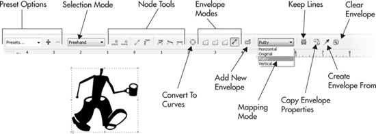
Choosing Envelope Mapping Options
You have envelope mapping options both for the Envelope docker and while using the Envelope tool and property bar options, which offer control over how the shape of an envelope changes your object’s shape (see Figure 20-5). As you can see, Original and Putty mapping provide almost identical results for this particular group of objects and the envelope shape used here, but Horizontal and Vertical Mapping afford the design opportunity to ignore the other envelope axis (Horizontal Mapping ignores the vertical aspect of the envelope, and vice versa). This is useful when you want limited distortion of an envelope but don’t have the time (or need!) to create a unique envelope for several different design purposes.

FIGURE 20-5 This object group uses the same envelope but different mapping options.
Mapping options give preference to the shape of your original object’s node positions and path shapes. Four types are available: Putty (the default), Horizontal, Vertical, and Original, as shown here:

The four envelope mapping options, plus a special option for text and another to preserve lines, are worthy of explanation here:
• Putty This option (the default) distorts the shape of your object to match the envelope as closely as possible; the envelope’s nodes are given priority over the nodes in your object being enveloped. The Putty option maps the envelope shape to your object and results in a smoothly mapped effect.
• Horizontal This option maps the lines and node positions in your original object to match the horizontal shape of the envelope, without significantly altering the vertical shape of the original object.
• Vertical This option maps the lines and node positions in your original object to the vertical shape of the envelope, with the horizontal shape mostly ignored.
• Original This mapping type is similar to Putty. The main difference is that Original maps only the outer shape of your original object to the envelope shape. Corner nodes are mapped to the corner nodes of your original object’s shape, while node positions and line shapes toward the inside of your object are mapped using an averaging value. The result can be less distortion. If Putty mode is too severe, try Original.
• Keep Lines Using this option changes only the node positions in your object to match the envelope shape being applied, leaving any existing straight lines unaffected. If your object is already composed only of curved lines, choosing Keep Lines has no effect, as shown at right in Figure 20-6, which looks like Keep Lines has been turned off. While Keep Lines is not selected (the default), all node positions and lines in your original object are reshaped to match the envelope object—even if this means changing straight lines to curved lines.
• Text This option becomes available as the only mapping option when a paragraph text object frame is selected. Text mode applies an envelope to the frame properties of a paragraph text object; the actual text and line of text are not distorted. This feature presents a wonderful opportunity to walk through a tutorial.
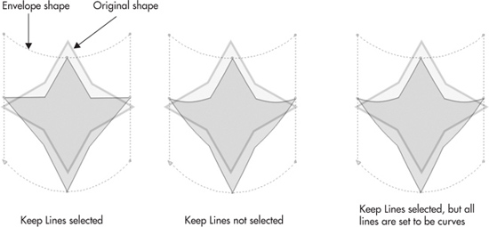
FIGURE 20-6 The Keep Lines option changes node positions but not any straight lines in the target object to match the envelope shape.
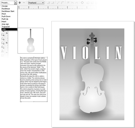
In the next set of steps, you’ll use the Violin.cdr file, which contains a silhouette drawing of a violin and a block of paragraph text attributed to Wikipedia. Your task is to fit the text inside the profile of the violin drawing. It’s a class act, and this technique can be used for scores of designs. Especially music scores.
Creating a Text Envelope
1. In the Violin.cdr document, choose the violin object with the Envelope tool.
2. On the property bar, click the + sign to the right of the Preset list. In the Save As box, save the custom envelope with an obvious name such as Violin.pst. Click Save to save and exit the box.
3. Select the block of paragraph text with the Envelope tool. Click the Preset list and then choose Violin from the list.
4. The edge of the newly enveloped text is going to look a little busy with the text offset margin and the envelope path around it; no big deal—choose the Pick tool (the envelope outline disappears), and move the text to fit over the violin drawing.
5. The “fit” is not perfect because the envelope effect is distorting the dimensions of the paragraph text block (but not the text itself) to match the proportions of the violin. Click-drag the object selection handles, and adjust the text so it fits neatly within the violin drawing.
6. With the Text tool, insert your cursor at the beginning of the paragraph, and then press ENTER to kick the text down so none of it is in the neck of the violin, which looks awkward, reads terribly, and makes it hard to play the instrument. See Figure 20-7 as a reference for where your composition should be now.
7. Optionally, choose a more elegant typeface than Arial. Select the text with the Pick tool, and then on the property bar choose a font you have installed. Figure 20-8 shows Bernard Fashion used. End of exercise, pretty fancy graphic use of the Envelope tool!
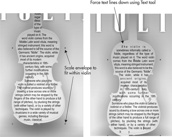
FIGURE 20-7 Perform a little manual editing to make the envelope text fit within the violin drawing.

FIGURE 20-8 Create an elegant symbiosis of text as a graphic combined with a simple CorelDRAW drawing.
Constraining Single Arc Envelopes
Modifier keys offer valuable ways to constrain the shaping of an envelope while using Single Arc mode. By holding key modifiers, you can quickly shape two sides concentrically or simultaneously. Hold SHIFT and drag any side or corner node to have the corresponding node on the opposite side move in the opposite direction. Hold CTRL to move the corresponding node on the opposite side of the shape in the same direction and by an equal distance, as shown in Figure 20-9.

FIGURE 20-9 By holding key modifiers, you can shape two sides either in the same direction (concentrically) or in opposite directions.
Using Envelope Shapes Between Objects
You can copy single-path objects—and even other envelopes—that already exist in your drawing, and use them as envelopes. The commands for these operations are available from the Effects menu and by using the shortcut buttons in the property bar when the Envelope tool is selected.
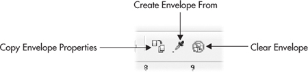
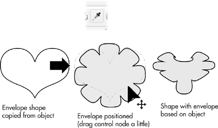
Copying Properties from Other Envelopes
If you’ve taken the time to create an envelope effect but you’ll only use it a few times so it’s not worth creating a preset, you can copy its properties to another object using the Copy Envelope Properties command. To copy an envelope’s properties, try the following steps.
Envelopes Based on Existing Envelopes
1. Select the object you wish to apply the envelope shape to, and choose the Envelope tool.
2. Click the Copy Envelope Properties button in the property bar. Your cursor will change to a targeting cursor.
3. Click to target the object with the applied envelope effect you wish to copy. The envelope effect is immediately copied and applied to the new object, as shown here:
TIP
If the envelope effect you need to copy from is on a different page of your document, try dragging a copy of the object onto the desktop (the pasteboard outside the document page). You can copy envelope shapes from the desktop.
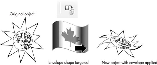
Creating Envelopes from Objects
Creating envelope shapes from existing objects is another common operation that enables you to create and apply new envelope shapes based on the targeted object’s shape. The steps are shown left to right here:
Unlike using the Copy Envelope Properties feature, copying a shape to apply to a different object as an envelope requires a little additional step. First, you target the object to be enveloped using the Envelope tool. Click the Create Envelope From button on the property bar, click the source object, and then a preview of the envelope shape appears around the target object. It doesn’t actually transform until you drag one of the control nodes just a little, or click an envelope path segment; then the target object transforms.
Clearing an Envelope Shape
Removing an envelope effect from an object is a quick operation. If you applied envelope effects in succession, all shaping can be removed at once. To remove an envelope effect, select the object bound to the envelope effect, and choose the Envelope tool. Click the Clear Envelope button.
TIP
The Clear Envelope command is also available by choosing Effects | Clear Envelope.
Copying Envelopes with the Attributes Eyedropper Tool
You can copy applied effects (including envelopes) from one single object (not grouped objects) to another by using the Attributes eyedropper tool. To do this, have both the objects in view. Got ’em? Follow these steps:
1. Choose the Attributes eyedropper tool from the toolbox.
2. On the property bar, click the Effects button, select the Envelope check box in the list, and then click OK.
3. Click the object currently applied with the envelope effect you want to copy using the Attributes eyedropper tool cursor to sample its properties.
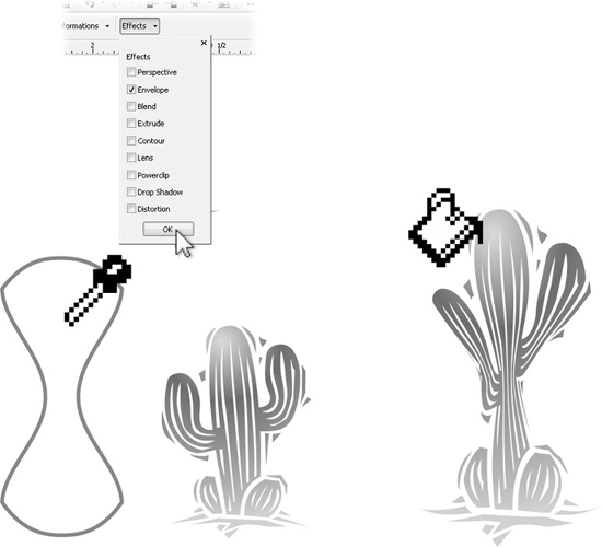
4. Click the object you want to apply the effect to.
TIP
You can apply several instances of an envelope, an envelope enveloping an envelope, and so on, if you need a truly gnarly effect. After you’ve sampled the envelope, click the cursor over the target object three or four times until your laughter subsides.
Mastering Distortion Effects
Distortion effects apply complex math to the curve paths that make up your object. But artists don’t need to know what’s under the hood in order to take advantage of these wonderfully intricate equations and to produce outstanding and very naturalistic artwork. The Distort tool and options are also dynamic, which means they create distortion without ruining your original. Distortion properties can be edited at any time. Your custom distortions can be saved as presets, and they can be cleared from your object, just like with envelopes.
Distortion effects also change your object without affecting its other properties such as outline width and fill. Using distortion, the curve values and node properties are dramatically changed, and the more complex your object is to begin with, the more dramatic the distortion effect will be. Adobe Illustrator users will feel right at home; although distortions are similar to Punk & Bloat, they go beyond this effect in variety and complexity, and when you’re using CorelDRAW distortions, you can restore your objects at any time. Distortion effects are great for a number of illustration challenges, including simulating organic-type effects, as shown in Figure 20-10. Believe it or not, the simple star shape at top left was used to generate the primitive cave scrawling. You can create flower shapes, zippers, swirly galaxies in space—not even the sky’s the limit.
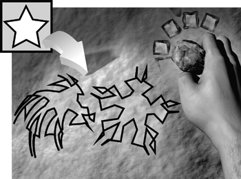
FIGURE 20-10 These primitive drawings were created by applying the Distort tool effects.
Using the Distort Tool and the Property Bar
Apply your distortions using the Distort tool, shown next, which is found in the toolbox grouped with other effects tools and is used together with these property bar options.
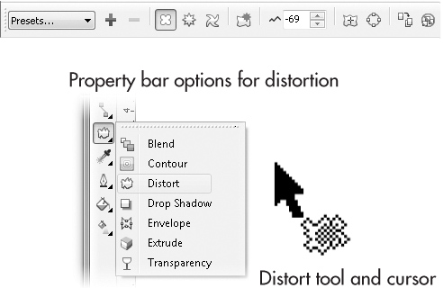
You’ll notice three distortion modes: Push And Pull, Zipper, and Twister. With each mode, a different set of parameters is available. Amplitude and Frequency values can be varied in combination with certain other options (covered next) controlled interactively or by setting values on the property bar. Let’s first look at the property bar when one of the modes, Zipper distortion, is chosen. All three modes offer slightly different options; by reviewing Zipper mode, you’ll get a handle on many of the options.
Choosing Distortion Modes
If you’ve tried using this effect, even just a little, you probably have a newfound appreciation for “steering” this effect—it’s akin to slipping into a Ferrari right after your dad took the training wheels off your bike. However, chin up, examples and explanations for this powerhouse of an effect follow, and as you read on (and get hands-on), the Distort tool will grow on you, and the intimidation factor will dwindle.
During a distortion session, interactive markers provide much of the control over this effect. Interactive markers vary by the mode selected. The distort modes are covered in the sections to follow in digestible, easy-to-assimilate, fun-size servings.
Push and Pull Distortion
Push and pull distortions can inflate or deflate the slope of your object’s curves by amplitude. The amplitude value affects the extent of the effect, sloping the curves of paths from an object’s original path from shallow at low settings to severe at high settings.
Amplitude can be set from 200 to –200 percent. Negative values cause the effect to distort the path away from the center origin of the object, which creates the “push” condition of the distortion. Negative values (which you can also define interactively with the Distort tool—it’s fun and creatively therapeutic) can be used to illustrate flower petals, a cartoon splash into a pond, a thought balloon—all beginning with a rectangle object. Positive amplitude values cause the effect to be distorted toward the object’s center origin, the “pull” condition. Again, if you use a rectangle as the target object, you can almost instantly produce anything from a diner sign from the 1950s, to a sleek, aerodynamic auto or airplane, to a nice 3D visualization of a TV tube viewed in perspective. The amplitude of 0 has no distortion. Figure 20-11 shows the effects of both negative and positive Push and Pull amplitude settings.
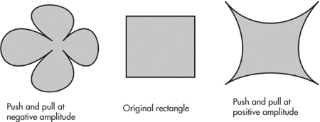
FIGURE 20-11 Amplitude can be set from 200 to –200 percent. But a little goes a long way!
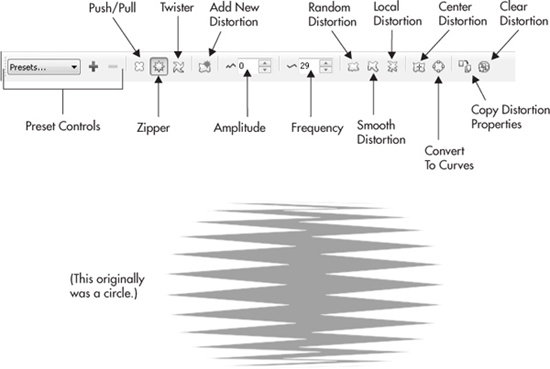
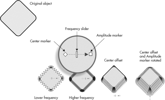
Zipper Distortion
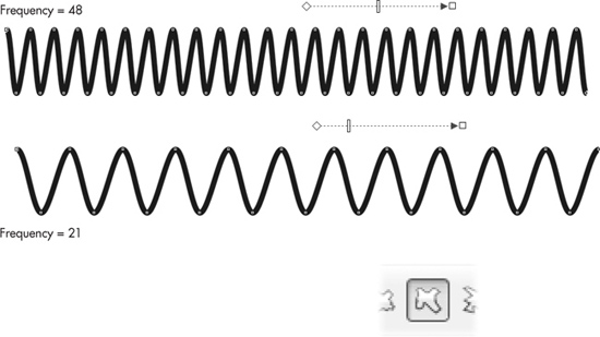
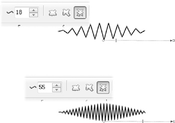
Zipper mode distorts the paths in your object to resemble a zigzag or stitching pattern. Here, amplitude can be set between 0 and 100 percent and can be used together with a frequency value and options for Random, Smooth, or Local distortion, as shown here:
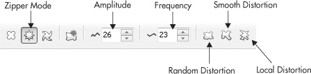
Interactive markers are made up of an outer marker controlling the amplitude and a slider controlling frequency, which enable you to set the number of zigzags within a given distance. Both can be set within a range of 0 to 100 percent. You can see the dramatic effects of various amplitude and frequency values while applying a zipper distortion in the next illustration. When beginning to work with the distortion effects, you might prefer to use only the property bar to define an effect, but as you grow more comfortable with distortion, you’ll surely want hands-on control by dragging the control handles directly with your cursor.
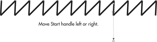
After the effect has been created, you can slant the zipper line by dragging the Start handle left or right, as shown here:
TIP
You can invert the direction of the zigzags on a line or closed shape by repositioning the control handles for the effect. For example, begin by placing the Start and End handles so they bisect the line that is affected. Then arrange the handles so both the Start and End handles are above the line; notice where the peaks and valleys are on the line. Now move the Start and End handles so they’re below the affected line. You’ll see that where there were peaks there are now valleys, and vice versa.
In addition to amplitude and frequency, three additional options are available for setting the shape and size of the zigzags. Each can be toggled on or off, so you can mix and match to create the following effects:
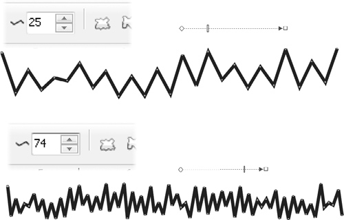
• Random Choosing the Random option causes the zigzag Zipper distortion on your object’s path to vary randomly between the current Amplitude values and zero. This creates the appearance of nonrepeating frequency and varied wave size, creating an uncontrolled distortion appearance. In this illustration you can see two examples of Random set at 25 and then at 74. Notice where the interactive frequency marker is on the controls just above each object. You can slide this marker instead of entering values on the property bar.
• Smooth While the Smooth option is selected, the cusps of the zigzag Zipper distortion become rounded, instead of the default sharp corners normally seen. This is a great option if you need to simulate sound-wave frequencies and equipment monitors in hospitals. The next illustration shows constant (Random is toggled off) Amplitude and variations in Frequency when the Smooth option is active.
• Local Using the Local distortion option has the effect of varying the Amplitude value of your distortion effect around the center origin. At the center of the distortion effect, Amplitude is at its maximum value. Amplitude then tapers to 0 as the distortion emanates from the center origin of the effect. The results of applying the Local distortion option while the Frequency is varied are shown here:
TIP
To clear a distortion effect, click Clear Distortion Effect in the property bar or choose Effects | Clear Distortion. If you’ve applied successive distortions, each distortion is cleared individually in order, from the last distortion applied to the first, so you can step out of the effect incrementally.
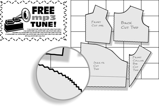
To bring all this Zipper talk down to a practical level, the following illustration shows two creative, commercial uses. At left, the Zipper distortion is used as a coupon border. The only finessing needed was to apply a dashed Outline pen style. At right, the diagram of a sewing pattern is gussied up a little by making the cut marks look as though real pinking shears were used.
Twister Distortion
Twister distorts the outline paths and nodes of objects by rotating the outer areas around the center (which is largely undistorted), either clockwise or counterclockwise, to achieve an effect much like a child’s pinwheel toy. Twister options on the property bar include rotation direction, rotation amount, and degree of additional rotation.
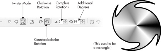
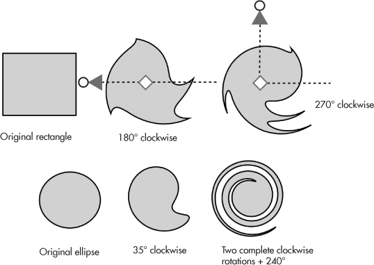
FIGURE 20-12 Using simple objects and the Twister mode of the distort effect, you can create wild, organic shapes.
Controlling a Twister distortion is simple; rotation can be clockwise or counterclockwise, but increasing the rotation really dramatizes the effect of this mode. Whole rotations can be set to a maximum of 9; additional rotations can be added up to 359°—nearly another full rotation. Figure 20-12 shows some of the widely differing effects that can result—it all depends on the number of rotations and the object used as the target for the effect.
NOTE
Objects applied with a distortion effect can’t be edited using the Shape tool unless the effect is cleared. However, you can convert a distorted shape to curves (CTRL+Q), and then edit to get the object you need.
Getting Hands-On with the Distortion Tool Markers
The best way to shape a distortion is interactively, by dragging directly on the Distortion tool markers with your cursor. Depending on which distortion mode you’re using, these interactive markers serve different purposes.
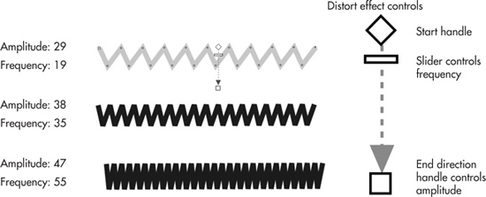
Which interactive markers are available depends on which mode (Push And Pull, Zipper, Twister) you’ve chosen, but basically you have a Start handle shaped like a diamond, which sets the center of the distort effect. The Start handle is connected to the End handle, which is used to define the direction of the effect and also the amplitude (with the Push And Pull and Zipper modes). Generally, interactive markers involve a center marker and at least one other, each joined by a directional guide. When Zipper distortion is being applied, a small extra slider appears between these two markers and controls the amount of frequency applied. In the case of Twister distortions, the outer marker serves as a handle for determining the degree angle and amount of rotation you apply to an object.
NOTE
To realign the center marker (the Start handle) with the center of the distortion, click the Center Distortion button in the property bar while the Distortion tool and the distorted objects are selected. It’s the button with the + symbol, to the left of the Convert To Curves button.
Changing Push and Pull Interactively
Push and pull distortions are controlled using two markers: a diamond shape indicates the center of the distortion, and a square marker controls amplitude. The center marker can be moved around the object, but the amplitude marker movement is constrained to left or right movement. Dragging the amplitude marker left of center changes the negative amplitude values, causing the push effect. Dragging it right of the center marker changes the positive values, causing the pull effect. Figure 20-13 shows the effects of different marker positions.
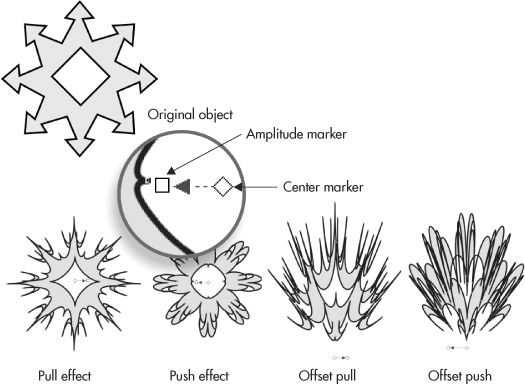
FIGURE 20-13 Push and pull distortions are controlled by a diamond shape and a square marker onscreen.
Working with the Zipper Control Handles
Using Zipper distortion, the movable diamond marker represents the center origin, and the square marker to the right controls the amplitude value. Use the small rectangular slider on the dashed blue centerline to set frequency by moving it left or right. Dragging it right increases the frequency, adding more zigzag shapes to your object’s path, while dragging it left does the opposite. You also have the opportunity with Zipper mode, unlike the fixed positions of the markers in Push And Pull mode, to move the amplitude handle to slant the zigs and zags in a direction.
TIP
Exactly as with envelopes, the distortion effects can be copied using the toolbox Attributes eyedropper tool.
Changing Twister Interactively
Controlling Twister distortions by dragging with your cursor over the markers is the most productive (and fun) way to apply this distortion mode; one click-drag lets you set two properties at once, both of which have a dramatic effect on the distortion. The markers during a Twister distortion are a diamond-shaped center marker and a round-shaped rotation handle. Dragging the rotation handle around the center marker causes distortion based on the angle of the guide between the center and rotation markers and the number of times the rotation marker is dragged completely around the center marker. You’ll also see a dashed blue line connecting the markers, which provides a quick visual reference of the beginning angle of the Twister distortion and the current angle of distortion you define. Figure 20-14 shows examples of Twister distortions and positions of the markers.
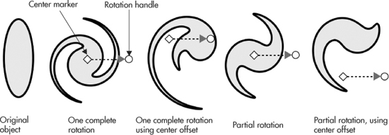
FIGURE 20-14 It’s best to use the control handles to create Twister distortions.
TIP
To copy a distortion to a new object, select an object, click the Copy Distortion Properties button in the property bar, and use the cursor to target an existing distortion.
Using Distortion Presets
The property bar Preset list for distortion effects gives you the power to apply, save, and delete saved distortions, as shown here:
Exploring Distortion Presets
When the Distort tool is the current tool selected, choosing a preset from the list immediately applies a new distortion effect to a selected object. If you’ve created a really awesome distortion effect and you want to save the effect while the distorted shape in your document is selected, you can add it as a new distortion preset by clicking the Add Preset button. The Delete Preset button permanently removes a selected distortion preset from the list; therefore, think twice about ever clicking this button. To delete a preset, nothing must be selected on the page; then the minus button becomes active. Only user presets can be deleted, not CorelDRAW shipped-with presets.
Between distortion and envelope effects covered in this chapter, you should be well on your way to massaging an object or object group from something close to what you like to exactly what you like and need. Remember, these are dynamic effects, so you don’t permanently change that shape you’ve worked for hours on. And if you need to exchange data with a client or coworker who doesn’t own CorelDRAW:
• Take pity on them.
• Convert a copy of your effects work to curves (CTRL+Q), and then export the distorted or enveloped object to any number of file formats CorelDRAW supports. Effects are proprietary to CorelDRAW, but vector information can be used in other vector design programs and modeling programs or exported as typefaces—you name it.
Blends and contours are the topic of the next chapter, each with their own use, and you can actually take what you know now about distortions and apply a contour to a distorted object. Will it look weird? Yep, and interesting. Just think of it as adding to weirdness, and building on your knowledge!