Chapter 9. Serial Ports
Yet all experience is an arch wherethro’ Gleams that untravell’d world whose margin fades For ever and for ever when I move.
—Tennyson, “Ulysses”
In this chapter, we’ll look at connecting your embedded systems to the outside world through the ubiquitous serial port. We’ll see how you implement the classic serial port, RS-232C, and even take a look at how you can power your embedded system through an RS-232C port. From there, we’ll take a look at the more robust RS-422, designed for faster data rates over longer distances. Finally, we’ll look at RS-485, an extension of RS-422 designed for low-cost networking of embedded computers.
We’ll start our examination of serial interfaces by looking at the engine that drives it all.
UARTs
Serial I/O involves the transfer of data over a single wire for each direction. All serial interfaces convert parallel data to a serial bit stream, and vice versa. Serial communication is employed when it is not practical, either in physical or cost terms, to move data in parallel between systems. Such serial communication may be between a computer and a terminal or printer, the infrared beamings of a Palm computer or remote control, or, in more advanced forms, high-speed network communication such as Ethernet. For embedded computers, a simple serial interface is the easiest and cheapest way to connect to a host computer, either as part of the application or merely for debugging purposes.
The simplest form of serial interface is that of the Universal Asynchronous Receiver Transmitter (UART). UARTs are also sometimes called Asynchronous Communication Interface Adapters (ACIAs). They are termed asynchronous because no clock is transmitted with the serial data. The receiver must lock onto the data and detect individual bits without the luxury of a clock for synchronization.
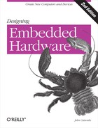
Figure 9-1 shows a functional diagram of a UART. It consists of two sections: a receiver (Rx) that converts a serial bit stream to parallel data for the microprocessor and a transmitter (Tx) that converts parallel data from a microprocessor into serial form for transmission. The UART also provides status information, such as whether the receiver is full (data has arrived) or that the transmitter is empty (a pending transmission has completed). Many microcontrollers incorporate UARTs on-chip, but for larger systems, the UART is often a separate device.
Serial devices send data one bit at a time, so normal “parallel” data must first be converted to serial form before transfer. Serial transmission consists of breaking down bytes of data into single bits and shifting them out of the device one at a time. A UART’s transmitter is essentially just a parallel-to-serial converter with extra features. The essence of the UART transmitter is a shift register that is loaded in parallel, and then each bit is sequentially shifted out of the device on each pulse of the serial clock. Conversely, the receiver accepts a serial bit stream into a shift register, and then this is read out in parallel by the processor.
Tip
UARTs actually predate semiconductor-based computers. In the early days of electrical communication, UARTs were mechanical devices with cogs, relays, and electromechanical shift registers. To adjust a UART’s settings, you first picked up a wrench!
One of the problems associated with serial transmission is reconstructing the data at the receiving end. Difficulties arise in detecting boundaries between bits. For instance, if the serial line is low for a given length of time, the device receiving the data must be able to identify if the stream represented “00” or “000.” It has to know where one bit stops and the next starts. The transmitting and receiving devices can accomplish this by sharing a common clock. Hence, in a synchronous serial system, the serial data stream is synchronized with a clock that is transmitted along with the data stream. This simplifies the recovery of data but requires an extra signal line to carry the serial clock. Asynchronous serial devices, such as UARTs, do not share a common clock; rather, each device has its own, local clock. The devices must operate at exactly the same frequency, and additional logic is required to detect the phase of the transmitted data and phase lock the receiver’s clock to this.
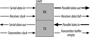
Asynchronous transmission is used in systems where one character is sent at a time, and the interval of time between each byte transmission may vary. The transmission format uses one start bit at the beginning and one or two stop bits at the end of each character (Figure 9-2). The receiver synchronizes its clock upon receiving the start bit and then samples the data bits (either seven or eight, depending on the system configuration). Upon receiving the stop bit(s) in the correct sequence, the receiver assumes that the transfer was successful and that it has a valid character. If it did not receive an appropriate stop sequence, the receiver assumes that its clock drifted out of phase, and a framing error or bit-misalignment error is declared. It’s up to the application software to check for such errors and take appropriate action.
The conversion from parallel to serial format is usually accomplished by dedicated UART hardware, but in systems where only parallel I/O is available, the conversion may be performed by software, which toggles a single bit of a parallel I/O port acting as the serial line.
Error Detection
In any transfer of data over a potentially noisy medium (such as a serial cable), the possibility of errors exists. To detect such errors, many serial systems implement parity as a simple check for the validity of the data. The parity bit of a byte to be transmitted is calculated by the sending UART and included with the byte as part of the transmission. The receiving UART also calculates the parity bit for the byte and compares this against the parity bit received. If they match, the receiver assumes that everything is fine. If they do not, the receiver then knows that something went amiss and that an error exists.
There are several types of parity, the main two being even parity and odd parity . In any byte of data, there is either an even number of “1” bits or an odd number of “1” bits. An extra bit (the parity bit) is added to the byte to make the number of “1” bits even (even parity) or odd (odd parity). For successful transmission, both the receiver and transmitter must be set for the same type of parity generation. There is no protocol for establishing common parity settings between UARTs; it must be done manually at either end.
So for the binary sequence %01000000, the parity bit would be “1” for even parity and “0” for odd parity. Similarly, for %11111111, the parity bit would be “0” if we were using even parity and “1” if we had odd parity. The generation and detection of parity is done automatically by dedicated hardware within the UART. It’s not something you explicitly have to calculate. You do have to make sure your UART is set to the correct type of parity generation; otherwise, it will not know how to process the parity information accordingly.
The parity bit is checked at the receiving end against the data to check whether any of the bits were corrupted during transmission. Say we sent %01000000. If our UART was set to even parity, the calculated parity bit from %01000000 would be 1. Now, let’s say this transmission was corrupted along the way, such that what was actually received was %01000001. The receiver would calculate the even parity of the byte to be 0. In comparing this to the received parity bit of 1, a parity error would be detected, and the receiver would take appropriate action (such as requesting that the byte be sent again). Note that how parity errors are handled is the responsibility of the programmer. The UART itself takes no action beyond flagging the error. It is up to the software to implement appropriate error handling.
Now, what if the medium was particularly noisy and two bits were corrupted? Again, if we sent %01000000 with even parity (computed parity bit = 1), and this was corrupted along the way to be %01001001, the receiver would calculate the even parity of the byte to be 1. The transmission was corrupted, but no parity error would be detected! As you can see, the usefulness of this form of error detection is extremely limited, and, for this reason, more complicated error detection (and correction) schemes are often implemented. A good example of this is the Cyclic Redundancy Check (CRC) algorithm. If you need to implement CRC, there’s plenty of source code available on the Web—just use your favorite search engine.
That covers the basics of how bits are transmitted serially. Now, it’s time to look at how you physically implement a serial interface. We’ll start with the old standard for serially connecting two computers (or just about anything else digital) together.
Old Faithful: RS-232C
RS-232C is a serial communication interface standard that has been in use, in one form or another, since the 1960s. RS-232C is used for interfacing serial devices over cable lengths of up to 25 meters and at data rates of up to 38.4 kbps. You can use it to connect to other computers, modems, and even old terminals (useful tools for monitoring status messages during debugging). In days of old, printers, plotters, and a host of other devices came with RS-232C interfaces. With the need to transfer large amounts of data rapidly, RS-232C is being supplanted as a connection standard by high-speed networks, such as Ethernet. However, it can still be a useful and (importantly) simple connection tool for your embedded system.
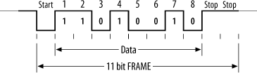
RS-232C is unbalanced, meaning that the voltage level of a data bit being transmitted is referenced to local ground. A logic high for RS-232C is a signal voltage in the range of -5 to -15 V (typically -12 V), and a logic low is between +5 and +15 V (typically +12 V). So, just to make that clear, an RS-232C high is a negative voltage, and a low is a positive voltage, unlike the rest of your computer’s logic.
The terminology used in RS-232C also dates back to the 1960s. In those days of mainframes, a high (1) was called a “space,” and a low (0) was called a “mark.” You’ll still find these terms kicking around in RS-232C, where you’ll hear phrases like “mark parity” and “space parity.” It’s also not unheard of to see RS-232C systems still using 7-bit data frames (another leftover from the ’60s), rather than the more common 8-bit. In fact, this is one of the reasons why you’ll still see email being sent on the Internet limited to a 7-bit character set, just in case the packets happen to be routed via a serial connection that supports only 7-bit transmissions. It’s nice how pieces of history still linger around to haunt us! More commonly, RS-232C data transmissions use 8-bit characters, and any serial port you implement should do so, too.
An RS-232C link consists of a driver and a comparator, as shown in Figure 9-3.
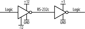
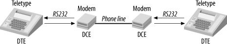
RS-232C also defines connectors and pin assignments, although there is a lot a room for variation (and thus a lot of incompatibilities exist). RS-232C was originally intended for connecting Data Terminal Equipment (DTE) to Data Communication Equipment (DCE) (Figure 9-4). The standard therefore assumes that at one end of an RS-232C link is a DTE device, and at the other end, there is a DCE. Before the advent of computers, a DTE was a terminal or teletype, and a DCE was a modem. The modem (MOdulator DEModulator) provided an interface to the phone line, and thereby a connection to a remote modem and terminal.
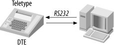
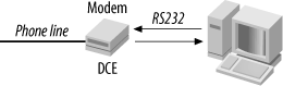
This worked simply and clearly in the days before desktop computers. The “problem” arises when you wish to connect either a terminal or a modem to the serial interface of a computer. Do you treat the computer as a DTE or a DCE? The RS-232C standard implies that if a terminal is at one end of the link, then the other end should be a DCE. So, if you were connecting a terminal to a Unix workstation, the RS-232C standard would like the workstation to be a DCE (Figure 9-5). Conversely, if you were connecting a modem to a computer, the computer should be a DTE (Figure 9-6). It’s all a bit schizophrenic.
Manufacturers, when faced with this problem, arbitrarily chose one or the other. The IBM PC has a DTE-type connector, whereas the makers of Unix workstations (such as Sun Microsystems) often choose to make their machines with DCE connectors, since they are more likely to be connected to terminals. To connect a PC to a modem, you need a DTE-DCE cable. To connect a PC to a terminal, you need a DTE-DTE cable. To connect a Sun workstation to a terminal, you need a DCE-DTE cable. To connect a Sun to a modem you need a DCE-DCE cable. To connect a Sun to another Sun, you need a DCE-DCE null modem cable (where Rx and Tx cross over), and to connect a Sun to a PC, you need a DCE-DTE null modem cable. If, however, you need to connect two PCs together, you need a DTE-DTE null modem cable. So, for just two types of device (DTE and DCE), you need six types of cable to cope with the permutations! Variety, as they say, is the spice of life, but it’s the bane of RS-232C!
Table 9-1 shows the “standard” connections for RS-232C, for both 25-pin and 9-pin connectors. The signal names are DTE-relative. For example, Tx refers to data being transmitted from the DTE but received by a DCE.
|
Signal |
Function |
25-pin |
9-pin |
Direction |
|
Tx |
Transmitted Data |
2 |
3 |
From DTE to DCE |
|
Rx |
Received Data |
3 |
2 |
To DTE from DCE |
|
RTS |
Request To Send |
4 |
7 |
From DTE to DCE |
|
CTS |
Clear To Send |
5 |
8 |
To DTE from DCE |
|
DTR |
Data Terminal Ready |
20 |
4 |
From DTE to DCE |
|
DSR |
Data Set Ready |
6 |
6 |
To DTE from DCE |
|
DCD |
Data Carrier Detect |
8 |
1 |
To DTE from DCE |
|
RI |
Ring Indicator |
22 |
9 |
To DTE from DCE |
|
FG |
Frame Ground (chassis) |
1 |
- |
Common |
|
SG |
Signal Ground |
7 |
5 |
Common |
Many of these signals are intended for modem control. To form a very simple link between a computer and a terminal, the only signals required are Tx, Rx, and SG. Many systems tie FG and SG together.
Shake Hands
When two remote systems are communicating serially, there needs to be some way to prevent the transmitter from sending new data before the receiver has had a chance to process the old data. This process is known as handshaking , or flow control . The way it works is simple. After transmitting a byte (or data packet), the transmitter will not send again until it has been given confirmation that the receiver is ready. There are three forms of handshaking: hardware, software, and none.
The no-handshaking option is obviously the simplest and is used in situations where the transmitting system is much slower in preparing and sending data than the receiver is in processing. For example, if you had a small, embedded computer running at a pokey 1 MHz that was feeding data into a high-speed computer system running at 4 GHz, it would not be unreasonable to assume that the faster machine would be able to keep up. However, if the faster machine is running a certain popular operating system (renowned for poor responsiveness to real-time events), it may very well be the case that it may not be able to keep up. In this case, handshaking would be required, and it’s probably good practice to incorporate it anyway. If you’re using the serial port to provide a human interface to your computer, then you can safely assume that no human will type faster than your computer can handle. So, for serial ports used solely for user access or debugging purposes, you can skip the handshaking.
Hardware handshaking in RS-232C uses two signals, RTS (Request To Send) and CTS (Clear To Send). When the transmitter wishes to send, it asserts RTS, indicating to the receiver that there is pending data. The receiver asserts CTS when it is ready, indicating to the transmitter that it may send. In this way, the flow of data is limited to the rate at which it may be processed.
Software handshaking, also known as XON/XOFF, is used where it is not possible to have hardware handshaking between the transmitter and receiver, such as when the transmission occurs over a phone line. Software handshaking chooses two characters to represent a request to “suspend transmission,” and a “clear to resume.” These are normally the characters Ctrl-S (0x13) and Ctrl-Q (0x11). The caveat is that you then can’t have these characters as part of the transmitted file, because they would be interpreted as flow control by the receiver and not as received data. If you’re only sending ASCII text, this is not a problem, but it can be a real headache if you’re sending binary data. The common solution is to preprocess the binary data prior to transmission and convert it to ASCII representation. For example, the byte 0x2F becomes the ASCII characters “2” (0x32) and “F” (0x46). Software on the receiving end converts the ASCII characters back into binary data again. Examples of software that will do this are uuencode under Unix and BinHex under Mac OS.
Implementing an RS-232C Interface
Adding an RS-232C interface to a system is easy. Most microcontrollers (except the very tiny) incorporate a UART within the chip, so all that is required is an external level shifter to convert the serial transmissions to and from RS-232C levels. Maxim makes a huge range of RS-232C interface chips (level shifters) that greatly simplify your design. No matter what your specific conversion requirements, doubtless there’s a Maxim part to meet your need. A good generic choice is the MAX3222 transceiver. Since nearly all RS-232C transceivers are used in the same way, looking at a design with a MAX3222 provides a good example of what to do for any transceiver. Unlike many other level shifters, the Maxim parts can operate from a low supply voltage, in the range of 3.0 V to 5.5 V. Many other manufacturers’ devices need supplies of +12 V and -12 V, and therefore require additional voltage regulators. The MAX3222 consumes minimal power (1 mA in normal operation and as low as 1 uA in shutdown mode), making it ideal for portable and battery-powered applications. If the ability to shut down the serial port into low-power operation is not required, the MAX3232 can be substituted. It is functionally the same, except that it lacks shutdown capability.
Using the MAX3222 is trivial, as there is almost no design work involved at all. The only external support components required are capacitors for the chip’s internal charge pumps. These pumps generate the +12 V and -12 V voltages required for RS-232C transmission, and they do so without requiring (additional) external voltage regulators. Figure 9-7 shows the schematic.
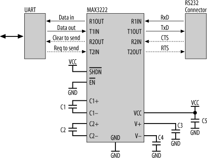
The capacitor C1 must be a minimum of 0.1 uF. If you are operating the chip at less than 3.6 V, C2, C3, and C4 can also be 0.1 uF. If the supply voltage is to be as high as 5.5 V, then C2, C3, and C4 must be a minimum of 0.47 uF. Since these are minimum values, larger capacitors may be used. However, if C1 is increased, then the remaining capacitors must also be increased accordingly. C5, the decoupling capacitor for VCC, is nominally 0.1 uF. All capacitors should be as close to the appropriate pins of the chip as possible.
The only remaining connections are the serial data lines from the UART and the signals to the RS-232C connector. If you are implementing a minimal serial interface, only Rx, Tx, and ground are required. RTS and CTS are optional. The RS-232C connector may be either a 25-pin or a 9-pin DB connector (its shape looks like the letter “D”). However, the connector could also be just a row of pins, a parallel header, or even just wires soldered directly onto the PCB.
The MAX3222 has two control inputs, ![]() (shutdown) and
(shutdown) and ![]() (enable).
(enable). ![]() places the RS-232C transmitters in high impedance, thereby disabling them. This reduces the chip’s current consumption to less than 1 uA. When in shutdown mode, the receivers are still active. Thus, the UART is still able to receive data even if the MAX3222 is in low-power mode. If
places the RS-232C transmitters in high impedance, thereby disabling them. This reduces the chip’s current consumption to less than 1 uA. When in shutdown mode, the receivers are still active. Thus, the UART is still able to receive data even if the MAX3222 is in low-power mode. If ![]() is not required, just connect it directly to VCC.
is not required, just connect it directly to VCC.
Similarly, ![]() is used to control the receiver outputs. Placing
is used to control the receiver outputs. Placing ![]() high puts the receiver outputs into high impedance, while the transmitter outputs are unaffected. To enable the receivers,
high puts the receiver outputs into high impedance, while the transmitter outputs are unaffected. To enable the receivers, ![]() is asserted (pulled low). If disabling the receivers is not required, then tie
is asserted (pulled low). If disabling the receivers is not required, then tie ![]() to ground to permanently activate them.
to ground to permanently activate them.
If needed, ![]() and
and ![]() may be controlled by a microcontroller’s I/O lines, or by simple digital outputs using a latch.
may be controlled by a microcontroller’s I/O lines, or by simple digital outputs using a latch.
The MAX3222 is sufficient to implement a minimal RS-232C interface, using just Rx, Tx, and ground. It also has additional drivers to support RTS and CTS, allowing for basic flow control. Should you require a full RS-232C interface, the MAX3241 is a good choice. Its operation is similar to the MAX3222, but it has additional transceivers allowing the inclusion of DTR, DSR, DCD, and RI for modem control. The MAX3421 may also be used to interface to a serial mouse, since it is able to meet the appropriate voltage and current requirements.
Using a Serial Port as a Power Supply
If an embedded system is to be permanently connected to a host computer via an RS-232C serial interface, it is possible to parasitically power the embedded system from the serial interface. Many RS-232C signals go unused and can supply a moderate amount of current, nominally 50 mA. However it can vary (considerably) from device to device, and, as always, you should check the specific system to which you are interfacing. If your embedded system requires less than this for its total current draw, you can use an RS-232C control signal for power.
For instance, the RTS (Ready To Send) or DTR (Data Terminal Ready) signals may not be used in many RS-232C applications. Either can be used as the power input to a voltage regulator, and thereby provide the system with power. The host computer therefore uses RTS of its serial port as the power control for the embedded system. Under software, the host sends RTS high, and the embedded system is powered up. If the host sends RTS low, the embedded system is powered down. The caveat to all this is to ensure that your embedded system’s current draw is low enough so that it can be powered by RTS. The advantage of this technique is that you require no external power supply for your embedded system. It works, as if by magic, whenever it is plugged into a serial port. The catch is that you can’t then use that RS-232C control signal for its original purpose. It must turn on and stay on to provide your embedded computer with power.
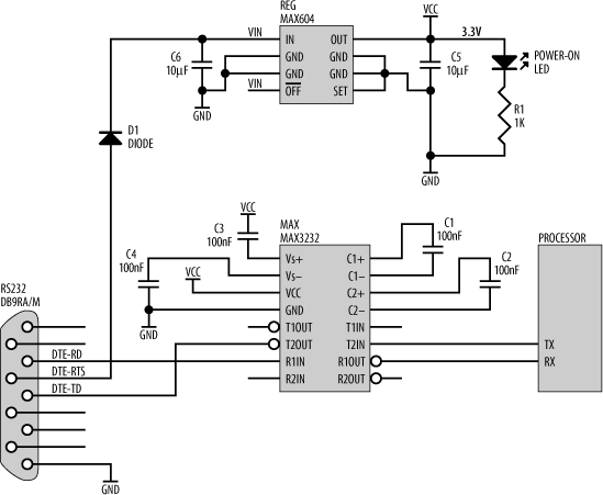
A sample schematic of this is shown in Figure 9-8, which also includes an RS-232C interface for a microcontroller, using a MAX3232. Note the diode, D1. Since RTS will be a negative voltage (as low as -15 V) when low, some protection is required for the voltage regulator, since it is not designed to have its input taken below zero volts. The diode can be any garden-variety power diode, such as a 1N4004, and will conduct only when RTS is positive. The voltage regulator (MAX604) converts the voltage from RTS to a supply of 3.3 V for the embedded system. If we required a supply of 5 V, we’d simply use a MAX603 instead. The circuit would otherwise be the same. The output of the regulator is smoothed by the capacitor C5, and a power-on LED is provided to show us when we have power. The MAX3232 sits between the RS-232C port and the processor, level-shifting the serial transmissions from the processor’s logic levels to RS-232C, and vice versa.
There we have the basics of RS-232C. It’s a very common interface that is easy to use, but it does have its limitations and quirks. It was originally intended for connecting dumb terminals and teletypes to modems, not for interconnecting computers and peripherals. A better choice is RS-422, designed for more robust and versatile serial connections.
RS-422
Unlike RS-232C, which is referenced to local ground, RS-422 uses the difference between two lines, known as a twisted pair or a differential pair , to represent the logic level. Thus, RS-422 is a balanced transmission, or, in other words, it is not referenced to local ground. Any noise or interference will affect both wires of the twisted pair, but the difference between them will be less affected. This is known as common-mode rejection . RS-422 can therefore carry data over longer distances and at higher rates with greater noise immunity than RS-232C. RS-422 can support data transmission over cable lengths of up to 1,200 meters (approximately 4,000 feet).
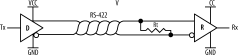
Figure 9-9 shows a basic RS-422 link, where a driver (D) of one embedded system is connected to a receiver (R) of another embedded system via a twisted pair. The resistor, Rt, at receiving end of the twisted pair is a termination resistor. It acts to remove signal reflections that may occur during transmission over long distances, and it is required. Rt is nominally 100-120 Ω.
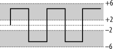
The voltage difference between an RS-422 twisted pair is between ±4 V and ±12 V between the transmission lines (Figure 9-10). RS-422 is, to a degree, compatible with RS-232C. By connecting the negative side of the twisted pair to ground, RS-422 effectively becomes an unbalanced transmission. It may then be mated with RS-232C. Since the voltage levels of RS-422 fall within the acceptable ranges for RS-232C, the two standards may be interconnected. RS-422 was the serial interface found on early Apple Macintosh computers, quietly dropped with the coming of the iMacs.
There is a wide variety of RS-422 interface chips available. Figure 9-11 shows a simple RS-422 bidirectional interface implemented using two Maxim MAX3488s. The Tx and Rx pairs of each MAX3488 are connected to UARTs within each embedded system, just as we did with RS-232C.
It’s important to note that RS-422 specifies only the voltages for the standard, not the physical implementation (pinouts or connectors). That is covered by RS-449. Now, no one seems to bother with RS-449, mainly because it is unnecessarily complex for most uses. People using RS-422 just seem to do their own thing, picking whatever cable and connectors (and pinouts!) they feel are appropriate for their application. Self-expression and RS-422 seem to go hand in hand.
Some RS-422 interface chips have an optional enable input. When enabled, the chip outputs and drives a transmission onto the twisted pair. When disabled, the chip’s output is high-impedance, and the chip appears “invisible.” Because of the ability of the interface chip to “disappear” from the connection, it is possible to have multiple interface chips (and therefore more than two embedded systems) connected to the twisted pair. In this way, it is possible to extend RS-422 into a low-cost, robust, simple network. When implemented in this fashion, it becomes RS-485.
RS-485
RS-485 is a variation on RS-422 that is commonly used for low-cost networking and in many industrial applications. It is one of the simplest and easiest networks to implement. It allows multiple systems (nodes) to exchange data over a single twisted pair (Figure 9-12).
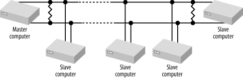
RS-485 is based on a master-slave architecture. All transactions are initiated by the master, and a slave will transmit only when specifically instructed to do so. There are many different protocols that run over RS-485, and often people will do their own thing and create a protocol specific to the application at hand.
The interface to the RS-485 network is provided by a transceiver, such as a Maxim MAX3483 (Figure 9-13).
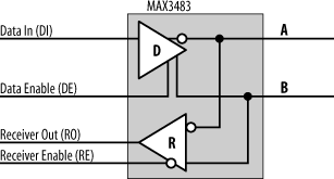
The MAX3483 is just an RS-422 transceiver with enable inputs, and using it in a design is straightforward. On the network side, the MAX3483 has two signal lines, A and B. This is the twisted pair (network cable) attachment point. The MAX3483 also has Data In (DI) and Receiver Out (RO). These are connected to the Tx and Rx signals of the UART (or microcontroller), respectively.
Since it is connected to a common network on which it must both listen and transmit, it has two control inputs, Data Enable (DE) and Receiver Enable (![]() ). A high input to DE allows the DI input to be transmitted on the network. A low input to DE disables the output of the transmitter. Similarly, a low input to
). A high input to DE allows the DI input to be transmitted on the network. A low input to DE disables the output of the transmitter. Similarly, a low input to ![]() enables the receiver, and network traffic is passed through to RO. DE and
enables the receiver, and network traffic is passed through to RO. DE and ![]() are normally controlled by an I/O line of the processor. Now, you’ll notice that DE is active high, and
are normally controlled by an I/O line of the processor. Now, you’ll notice that DE is active high, and ![]() is active low. This is not by chance. A node on the network won’t be receiving traffic if it’s transmitting and, conversely, won’t be transmitting if it is receiving. Therefore, only one of the two—the transmitter or the receiver—should be active at any one time. If the transmitter is on, the receiver should be off, and vice versa. The control for the transmitter is therefore the logical opposite of the control for the receiver. By having DE active high and
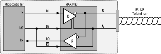
is active low. This is not by chance. A node on the network won’t be receiving traffic if it’s transmitting and, conversely, won’t be transmitting if it is receiving. Therefore, only one of the two—the transmitter or the receiver—should be active at any one time. If the transmitter is on, the receiver should be off, and vice versa. The control for the transmitter is therefore the logical opposite of the control for the receiver. By having DE active high and ![]() active low, a single control line may be used for both. Figure 9-14 shows a MAX3483 interfaced to a microcontroller in this way. The microcontroller normally has DE/
active low, a single control line may be used for both. Figure 9-14 shows a MAX3483 interfaced to a microcontroller in this way. The microcontroller normally has DE/![]() low so that it is listening to network traffic. When it wishes to transmit, it sends DE/
low so that it is listening to network traffic. When it wishes to transmit, it sends DE/![]() high. Upon completion of transmission, it returns DE/
high. Upon completion of transmission, it returns DE/![]() low and resumes listening.
low and resumes listening.
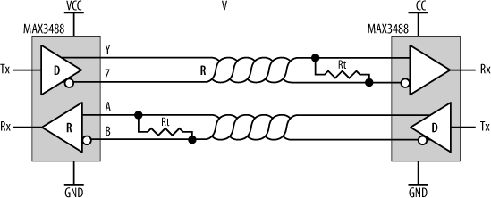
RS-485 may be implemented as half duplex , where a single twisted pair is used for both transmission and reception (Figure 9-15), or full duplex , where separate twisted pairs are used for each direction (Figure 9-16). Full-duplex RS-485 is sometimes known as four-wire mode . Note that for full-duplex operation, the MAX3483s are replaced with MAX3491s that have dual network interfaces.
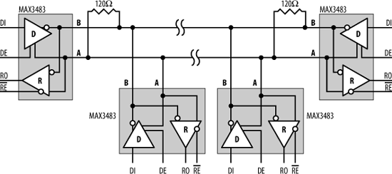
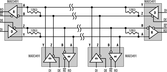
These examples show four computers (nodes) connected to an RS-485 network. Each RS-485 interface chip (MAX3483 or MAX3491) exists in a separate embedded computer. The UART transmitter output, Tx, in each embedded system is connected to the respective DI of each of the RS-485 interface chips. Similarly, RO connects to the Rx input of each UART. The driver of each RS-485 interface chip is enabled by asserting DE, and, similarly, reception is enabled by asserting ![]() .
.
Normally, all systems connected to the RS-485 network have their receivers enabled and listen to the traffic. Only when a system wishes to transmit does it enable its driver. There are a number of formal protocols that use RS-485 as a transmission medium, and twice as many homespun protocols as well. The main problem you need to avoid is the possibility of two nodes of the network transmitting at the same time. The simplest technique is to designate one node as a master node and the others as slaves. Only the master may initiate a transmission on the network, and a slave may only respond directly to the master, once that master has finished.
The number of nodes possible on the network is limited by the driving capability of the interface chips. Normally, this limit is 32 nodes per network, but some chips can support up to 512 nodes.