
7.2. The ITU-T G.7713 Model
7.2.1. What Is G.7713?
G.7713 [ITU-T03a] is an ITU-T recommendation dealing with distributed call and connection management in optical networks conforming to ITU-T G.8080 architecture [ITU-T01d]. The purpose of this recommendation is to describe the parameters and procedures related to signaling independent of any particular signaling protocol. To do this, certain functional requirements and an architectural model for signaling are assumed. The main utility of G.7713 is the specification of the signaling interfaces, and the development of an architectural model that separates the signaling control plane from the data transport plane in optical networks. G.7713 also contains signaling message flow descriptions, and call and connection control finite state machine descriptions. From a practical perspective, these are not as significant, since such features are typically part of established signaling protocols such as RSVP-TE and PNNI.
7.2.2. Architectural Aspects
7.2.2.1. SIGNALING INTERFACES AND THE CONTROL PLANE
Fundamental to the architectural model described in G.7713 are the definitions of the signaling interfaces and the separation of the control plane from the data plane in optical networks. This is illustrated in Figure 7-4, where the optical network shown consists of a series of n control domains (or simply, domains). A domain, as described in section 5.2 (in Chapter 5), encloses a part of the overall network. In the simplest case, a domain could consist of a set of interconnected NEs. In the general case, it could be topologically partitioned, consisting of a set of interconnected subnetworks. This is the case depicted in Figure 7-4.The following signaling interfaces are identified in this figure:
UNI (User-Network Interface): The signaling interface between the external user (client) network and the optical network.
I-NNI (Interior Network-Network Interface): The signaling interface between subnetworks within a control domain (in the simplest case, each subnetwork is a single NE).
E-NNI (Exterior Network-Network Interface): The signaling interface between control domains.
Figure 7-4. G.7713 Reference Model
The difference between these interfaces lies in the type and format of information that may be sent across in signaling messages. Specifically, the UNI is the interface over which a client device requests service from the optical network. The signaling messages over this interface pertain to establishing, tearing down, and modifying connections to a remote end point to which a destination client is attached. As mentioned at the beginning of this chapter, the more traditional method is for the client network operator to request service from the operator of the optical network. These two methods result in two different types of connections. When a UNI is used to signal service request, a switched connection is provisioned in the network. When the optical network operator provisions a connection through a management system, it is called a soft permanent connection.[1] Regardless of how a service request originates, certain parameters are typically associated with subsequent connection provisioning within the optical network. Some of these were shown in Figure 7-1.
[1] Although all connections depend on switching inside the network, the terminology “switched connection” is used to indicate a connection that can be set up and torn down dynamically based on user request. The terminology “soft permanent” is used to indicate a connection that remains up until the network operator explicitly deletes it.
The NNI is the interface across which the actual connection establishment, tear down, and modification messages flow between subnetworks (within or across domains). Unlike the UNI, the NNI messages may carry information about the connection route, endpoint addressing information, and other parameters of use internally within the optical network. The Interior and Exterior NNI differ mainly in the flow of routing and policy related information across the interfaces.
Figure 7-4 also illustrates the separation between the control plane logical functions and its physical realization. The following entities are indicated in the figure. In the following, the notation “A” and “Z” are used to denote the two endpoints of signaling communication:
A-RA and Z-RA: These are the A-end and Z-end Requesting Agents on the user side. An RA is a control plane entity that signals on behalf of an external user subnetwork (which contains the data transport equipment). This is a logical entity, that is, this could be physically realized as part of the equipment that has the data plane functionality, or as a separate piece of equipment. In the latter case, a single RA can represent multiple network elements, and there has to be a communication interface between the RA and the network elements it represents. This is necessary in order to coordinate the control plane and the associated data plane functions (e.g., establishment of data plane cross-connects, commencement of data transmission when connection establishment is complete, etc.).
A-USN and Z-USN: These are the A-end and Z-end User Sub-Networks. A USN is the collection of NEs that form the user-side subnetworks. As described earlier, the A-RA and Z-RA implement the control plane functionality for these subnetworks.
A-SC, I-SC and Z-SC: These are the Subnetwork Controllers for the ingress, intermediate, and egress subnetworks within a domain, respectively. As described before, a domain consists of a series of subnetworks (or individual NEs), and an SC represents the logical entity that implements the control plane functions within a subnetwork. As with the A-RA and the Z-RA, an SC can be physically realized as part of an NE, or it can be a separate physical entity. In the latter case, a single SC can represent multiple underlying NEs, and there is a need for a communication interface between the SC and the NEs it represents.
A-NSN, I-NSN and Z-NSN: These are the ingress, intermediate, and egress network-side subnetworks, respectively. The A-SC, I-SC and Z-SC implement the control plane functionality corresponding to these subnetworks.
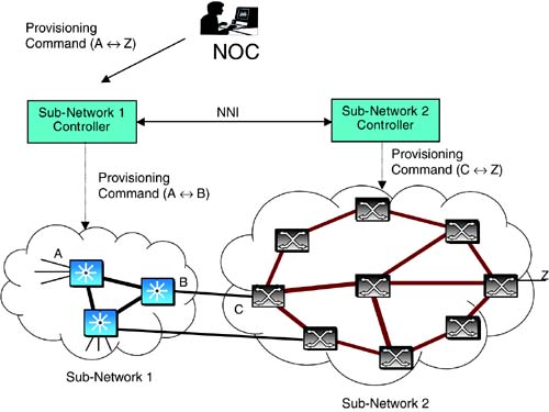
We have seen that the above architectural model separates the logical control plane functionality from its physical realization. What is the advantage of doing so? The separation mainly addresses a practical issue that arises in dealing with heterogeneous subnetworks. Consider an operator who wants to integrate two subnetworks, one that uses a management system for provisioning and another that uses proprietary signaling. By establishing two subnetwork controllers and using standard NNI signaling between them, the operator can implement end-to-end connection provisioning. This is illustrated in Figure 7-5. But instead, assume that both these subnetworks utilize internal signaling for provisioning. Then, the NNI will be directly between the border nodes in these subnetworks (i.e., the controller functionality will be present directly in the NEs).
Figure 7-5. Sub-Network Provisioning
7.2.2.2. CALL AND CONNECTION CONTROL
The G.7713 architectural model makes a distinction between a call and a connection. A call is a set of related connections between the same two end points. The signaling over the UNI establishes a call from the user perspective. The call is thus relevant to the user equipment at both ends, and to the ingress and egress NEs in the optical network. Within the network, connections are established, and the correlation of connections belonging to the same call are done at the ingress and egress NEs. In practical terms, a call is created when the first connection within is created; it is modified when connections within are added, removed, or modified; and it is deleted when the last connection within is deleted.What is the advantage of distinguishing between a call and a connection? As per G.7713, the following features are enabled by this separation:
It permits the implementation of nondisruptive connection modification, whereby a new connection is added to a call and an existing connection deleted after traffic is moved from the latter to the former in a “hit-less” manner. Briefly, the ingress and egress NEs in the optical network keep the association between the connections by treating them as part of the same call. Intermediate NEs do not need this association. Readers may refer to the sections on LCAS and Virtual Concatenation in Chapter 3 for applications.
Similar to the connection modification feature above, it allows a “working” connection to be related to a “protection” connection, and traffic to be switched from the former to the latter when failures occur.
A call with zero connections within is possible. This allows the ingress/egress NEs to maintain “call state” relating to communication that has been disrupted inside the network. For instance, an ingress NE might be looking to reestablish a connection that has been deleted inside the network due to a failure condition.
In essence, the concept of a call formalizes the notion of maintaining state information that correlates connections. The same functionality is accomplished in GMPLS signaling using additional identifiers in connection signaling.
7.2.2.3. CONNECTION PROVISIONING
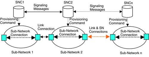
The connection provisioning procedure under the G.7713 model is illustrated in Figure 7-6. Here, an end-to-end connection is provisioned as a series of segments, some of them over single links and the others within subnetworks. Each controller that processes a signaling message in the first phase of connection provisioning has to determine the next controller to forward the signaling message, as well as local resource assignments for the connections. Routing information to determine the next controller may or may not be present in the signaling message. If it is not present, the controller must compute a partial route. The assignment of local resources would depend on the parameters of the connection. Furthermore, in the case of subnetwork controllers, determining local resources might require the determination of the entire path within the subnetwork for the connection segment.
Figure 7-6. End-to-End Connection Provisioning Across Sub-Networks
The detailed functionality implemented for connection provisioning will be clear when we look at specific signaling protocols. The G.7713 recuommendation, however, describes only general principles. Specific protocols that adhere to this model are separately defined. So far, three existing protocols have been adapted to provide the functionality described in G.7713: P-NNI, RSVP-TE and CR-LDP [ITU-T03b, ITU-T03c, ITU-T03d].
We defer discussion of protocols until later, and look at GMPLS signaling next.