
6.4. LMP
LMP is a protocol being standardized by the IETF. Its functionality includes:
Link connectivity verification: Supports the discovery of topological links between adjacent OXCs or PXCs.
Link parameter correlation: Supports the exchange of link parameters between adjacent NEs.
Control channel management: Allows the health of the control channel(s) between two adjacent NEs to be monitored.
Link fault localization: Allows the localization of faults occurring in topological links between PXCs.
LMP has been designed to accommodate OOO switches (PXCs) with their limitations on in-band communication capabilities (i.e., overhead bytes cannot be used for communication). Thus, LMP functions are somewhat more complex than what is required for just SONET/SDH neighbor discovery.
LMP runs as an application over UDP and IP. Thus, LMP requires a means for an NE to send and receive IP packets to/from adjacent NEs. This means that a control channel has to be configured between neighbors before LMP begins running. This is in contrast to the SONET/SDH neighbor discovery description earlier, where a control channel was not always required. In the following, we look at various options for realizing control channels.
6.4.1. Control Channels
Control channels between a pair of NEs for carrying IP packets can be realized in two ways:
In-fiber control channel: The IP packets are carried over a communication channel embedded in the data-bearing topological link between the NEs.
Out-of-fiber control channel: The IP packets are carried over a dedicated communication link between the NEs, separate from the data-bearing topological links.
These options are described further below.
6.4.1.1. IN-FIBER CONTROL CHANNELS OVER SONET/SDH DCC BYTES
The idea of transporting packets over SONET/SDH DCC bytes was described earlier. Suppose there is more than one link between two OXCs, and the DCC bytes on each link could be used to create a control channel. The functional components of the control path between the OXCs in this case are shown in Figure 6-16. Here, an IP packet generated by an NE is first passed to a channel manager. This entity is responsible for selecting one of the possibly many physical communication channels available to its peer. A driver prepares the packet for transmission, and the transmission hardware is responsible for framing the packet, serializing it, and physically transmitting it over the selected overhead bytes to the peer. At the destination, the transmitted frames are extracted from the overhead bytes, and the IP packet is recovered and delivered to the IP destination. Thus, an in-fiber control channel is logically equivalent to a unidirectional point-to-point IP link. The channel manager essentially maintains a collection of such point-to-point links, monitors their status, and determines which link to use when sending a packet to a neighbor. An essential feature of this mechanism is that an IP packet transmitted over any of the available physical channels is received by the destination. This means that there is no coordination required a priori between the transmitter and receiver to determine which of the many physical channels should be used for sending a given packet.
Figure 6-16. Functional View of In-Fiber Transport

The IP packets sent in this manner must have a destination IP address that refers to the neighboring NE. The automatic discovery by one NE of the other's IP address, the selection and maintenance of the control channel, and so on, are described in section 6.4.2.
6.4.1.2. OUT-OF-FIBER CONTROL CHANNELS
In this case, the IP packets are transported over a separate control network that is distinct from the data network. Figure 6-17 illustrates an example where two NEs have points of attachment to two distinct IP networks (also called the Data Communication Network or DCN). In the simplest case, these could be local area networks (LANs). Control messages may be sent over either network without coordination. But each NE must be configured with a routable IP address of the other in order to send packets.
Figure 6-17. Out-of-Fiber IP Control Channels

Although two distinct control channel configurations were described, more than one type of control channel may exist between a pair of NEs. For instance, there could be both in-fiber and out-of-fiber control channels. Similarly, an NE could have different types of control channels with different neighboring NEs. Thus, NEs must be configured with information indicating which type of control channel is implemented for which set of data links.
6.4.2. LMP Usage with OEO Cross-Connects (OXCs)
In this section, we describe one scenario for LMP usage in SONET/SDH networks with OXCs, where line or section DCC bytes in each link are used for packet communication. The relevant functions are link connectivity verification, control channel maintenance, and link property correlation. These are described below.
6.4.2.1. BASIC LMP PARAMETERS
The fundamental LMP parameters of importance for neighbor discovery are:
Node ID: This is a network-wide unique 32-bit identifier assigned to an NE.
Interface ID: This is an identifier assigned to each interface in an NE. The interface ID must be unique within the scope of a given node. The interface ID could be a 32-bit IPv4 address. The interface ID corresponds to the Port ID we used in earlier descriptions.
Control Channel ID (CCID): Every control channel terminating at an OXC must be assigned a unique identifier. This is called the CCID, and it is a 32-bit number that is unique within the scope of a Node ID. LMP considers both in-fiber and out-of-fiber control. For in-fiber control channels, the CCID is the same as the interface ID. Out-of-fiber control channels must be assigned their own identifiers. If a node has both in-fiber and out-of-fiber control channels then they must all have unique IDs. Also, the same control channel between two OXCs may be assigned different CCIDs at the two ends.
LMP messages have the following format: <LMP common header>followed by <Message body>. The LMP common header is shown in Figure 6-18. The numbers beside the field descriptions indicate the length of the field in bits. The header consists of the following fields:
Flags: This field indicates various values, depending on the specific LMP message. Details can be found in [Lang+03a].
Message Type: The type of LMP message. Of relevance to neighbor discovery are Config (1), ConfigAck (2), ConfigNack (4), and Hello (5).
LMP Length: The total length of the LMP message in bytes, including the common header and any variable-length objects that follow.
Checksum: The standard IP checksum of the entire contents of the LMP message, starting with the LMP message header.
Figure 6-18. LMP Common Header

The LMP object format is shown in Figure 6-19. This is similar to the object definition under RSVP (see Chapter 7). The “N” bit indicates whether the parameters encoded in the object are negotiable (N = 1) or not (N = 0).
Figure 6-19. LMP Object Format

6.4.2.2. LINK CONNECTIVITY VERIFICATION
This procedure is executed independently for each link. Given that each link supports a packet-based communication channel, initial neighbor discovery is performed through the exchange of LMP Config messages over the channel. This message exchange allows adjacent NEs to determine the logical link end point associations, and to determine errors in connectivity. After this step, Hello messages are repeatedly sent over the DCC channel to keep track of its status (“up” or “down”). When there is a disruption in the Hello protocol (e.g., a Hello message is not received within an expected time period) or when an interface is locally initialized, the Hello protocol is stopped, and the status of the corresponding channel is marked “Down.” In this case, configuration messages are exchanged again to determine changes in identification of the topological link.
Config Message Exchange
This message exchange allows the determination of the link identity and to configure the Hello protocol parameters. The configuration step consists of exchanging two LMP messages: Config, and ConfigAck or ConfigNack. The NE that initiates neighbor discovery sends a Config message to its peer over the control channel. This message contains the link identification information at the sending NE and Hello protocol parameters. An NE receiving a Config message responds with a ConfigAck or a ConfigNack message, indicating the acceptance or the rejection of parameters in the Config message. The reception of a ConfigAck message by the sender of the Config message completes the configuration process. The reception of a ConfigNack message, on the other hand, may terminate the configuration process unsuccessfully, or may result in the transmission of another Config message with revised parameters.
A Config message may be sent concurrently by the two NEs to each other. In this case, the NE with a numerically lower Node ID stops sending Config messages and responds to the received Config message. The other NE ignores the received Config messages and waits for a ConfigAck or a ConfigNack message.
The Config Message
The essential contents of the Config message are shown in Figure 6-20. This includes the Node ID of the sending node, the interface ID of the logical link (in the Local CCID field), and parameters pertaining to the Hello protocol that will follow. These parameters are:
Hello Interval: The frequency with which this NE will send Hello messages over the control channel. This is given as the time between two consecutive Hello messages in milliseconds.
Hello Dead Interval: The maximum amount of time this NE will wait to receive Hello messages from the other end before declaring the logical link as “down.”
Figure 6-20. Config Message

Because the NE sending the Config message does not know the identity of the NE at the other end, the destination address of the IP packet containing the message is set to the “all nodes” multicast address, 224.0.0.1.
The ConfigAck Message
The ConfigAck message indicates that the Hello parameters received in the Config message are acceptable to the receiving node. Its essential contents are shown in Figure 6-21. This includes the Node ID of the sending node and the local interface identification (in the Local CCID field), as well as the received Node ID and link identification (in the remote Node ID and the remote CCID fields, respectively).
Figure 6-21. ConfigAck Message

The ConfigAck message is sent to the source IP address found in the packet containing the Config message. The ConfigNack message is used to reject/negotiate parameters received in the Config message.
Neighbor Discovery Examples
Figure 6-22 illustrates neighbor discovery using LMP. The Config message exchange allows each NE to build the “Remote Node ID” and “Remote Interface ID” fields of the link identification table shown in Figure 6-15.
Figure 6-22. Neighbor Discovery LMP Message Exchange

Inconsistent interface connectivity is detected by an NE when either a ConfigAck (or a Nack) message is not received in response to a Config message that has been sent, or when a ConfigAck or a Nack message that it receives does not contain the expected Node ID or link end point identification. This is illustrated in Figure 6-23. Here, the transmit and receive sides of NE-1 interface 1 are connected (wrongly) to receive and transmit sides of NE-2 interfaces 10 and 11, respectively. Thus, in response to a Config message sent over interface 1, NE-1 receives a ConfigAck message with Received CCID = 2. Similarly, in response to a Config message sent over interface 2, the NE receives a ConfigAck message with Received CCID = 1. This allows the detection of inconsistent connectivity.
Figure 6-23. Detecting Inconsistent Interface Connectivity

The Hello Protocol
Each NE executing the Hello protocol must periodically send a “Hello” message over the DCC channel. The IP destination address in these messages is set to the Node ID obtained during the configuration procedure. The periodicity of the Hello message is governed by the Hello interval established during the configuration phase.
The Hello message contains a transmit and a received sequence number. The transmit sequence number is the sequence number of this Hello message, and the received sequence number is the sequence number of the last Hello message received by the sender. If an NE is sending Hellos but does not receive any Hellos during the Hello dead interval period, the corresponding channel is declared down. More details of the Hello procedures can be found in [Lang+03a].
6.4.2.3. LINK PROPERTY CORRELATION WITH A DISTRIBUTED CONTROL PLANE
LMP defines three messages for link property correlation. These are Link Summary, Link Summary Ack, and Link Summary Nack messages. Briefly, the Link Summary message is sent by an NE over the control channel (in-fiber or out-of-fiber) to indicate the configured values for an identified link. Note that this message is sent only after neighbor discovery has been completed. The remote NE compares the received values with those configured for the same link on its side. If they match, a Link Summary Ack message is sent. Otherwise, a Link Summary Nack message is sent. More details can be found in [Lang+03a].
So far in this section, we have considered neighbor discovery over DCC bytes. What if J0 bytes are used? The LMP procedures in this case would use Test messages over J0 bytes, similar to the Test message usage defined for PXCs next.
6.4.3. LMP Usage with Photonic Cross-Connects (PXCs)
Neighbor discovery is more complicated with PXCs. Specifically, consider automatic link identification. This function requires in-fiber communication capability between PXCs. But PXCs merely switch light from an incoming to an outgoing port and they do not terminate overhead bytes. So what is the solution?
The first step is to introduce additional hardware that allows a PXC to electrically generate and terminate “test” signals that may be used to probe topological links to different neighbors. This is illustrated in Figure 6-24. Here, a signal generating/terminating hardware is permanently connected to one port of each PXC. A “test” message generated by this hardware can be cross-connected to any of the outgoing ports. Similarly, a “test” message received on an incoming port can be cross-connected to the port attached to the test generator/terminator. An important assumption here is that the framing and rate of signals carrying “test” messages are compatible with the DWDM transponders to which the output ports of the PXC are connected (see Figure 6-4). This implies homogeneity in the signal rates switched by the OXC.
Figure 6-24. Test Procedure with Transparent OXCs

The use of this hardware to perform link identification is described in more detail next. For the present, let us consider the cost of providing neighbor discovery capabilities in PXCs. First, the test generator/terminator hardware is required. This may be a piece of external equipment or built internally in each PXC. Second, a port in each PXC has to be dedicated for connecting to the “test” generator/terminator. These are in addition to at least one out-of-fiber control channel required between adjacent PXCs. A case, however, can be made that such dedicated hardware and switch resources are also useful for verifying end-to-end connectivity during provisioning. That is, a service provider can verify whether a connection has been properly provisioned, before turning it over to the customer, by generating a “test” message at one end, switching it through the provisioned path, and receiving it on the other end. On the whole neighbor discovery is more complex with PXCs, both from the hardware requirements perspective and from the protocol perspective.
In the following, the neighbor discovery procedure is described in more detail.
6.4.3.1. LINK CONNECTIVITY VERIFICATION
Consider a PXC with a set of topological links to one or more neighboring PXCs. In the opaque (SONET/SDH) network case, the link identification procedure would allow an NE to automatically determine the complete identity of each link, that is, the Node ID of the NE at the other end, as well as the remote interface ID. Doing exactly this with PXCs is rather complex. In fact, a lesser goal is often considered. To be specific, suppose the remote Node ID for each link (i.e., the identity of the neighbor) is manually configured in each PXC. Furthermore, let us assume that the out-of-fiber control channel associated with each neighbor is also configured. Then, the link identification procedure can determine the remote interface ID for each link automatically. Clearly, it looks like we are doing half the work manually in this case, and the functionality provided by “automatic” neighbor discovery is rather limited. This is indeed true, and LMP provides only this functionality with PXCs. The usefulness of automatically discovering just the remote interface IDs is debatable. This is especially the case given the requirements for additional hardware and switch resources. Let us, however, consider the procedure for this first and then look at why it is difficult to determine the complete link ID automatically.
6.4.3.2. PROCEDURE
Consider a PXC with the following configured information:
Its own Node ID.
The local identities of all topological links (the local interface IDs).
The identity of each neighbor along with the identity of the out-of-fiber control channel to be used to reach the neighbor (see Figure 6-17).
For each topological link, the Node ID of the neighbor to which the link is connected.
Note that the last two items need not be configured with OXCs. Furthermore, looking at the link identification table (Figure 6-15), what is left to be determined is the remote interface ID. To determine this, the PXC does the following:
1. | It selects a neighbor. |
2. | It sends a message over the control channel to the selected neighbor indicating that it will begin sending a “test” message over each topological link connected to the neighbor. |
3. | After confirming that the neighbor is willing to receive “test” messages, it selects a link to the neighbor to send these messages. |
4. | It sends test messages repeatedly over the selected link until the neighbor acknowledges that a message has been received. At this time, the neighbor also indicates the interface ID on its side over which the test message was received. |
5. | The PXC notes down the remote interface id in its link identification table. |
6. | It then selects another link, and Steps 4 and 5 are repeated until the remote interface IDs of all the links to the selected neighbor are determined. |
7. | It notifies the neighbor of the end of link identification. |
8. | Steps 1–6 are repeated for each neighbor. |
Now, from the point of view of the neighbor participating in this procedure, the following events occur:
- It receives a request from a neighbor that is going to send “test” messages.
- It determines if it can participate in this procedure. For instance, it is possible that its test message terminating hardware (Figure 6-24) is busy because it is participating in a test procedure with another neighbor. It then sends a message back indicating its willingness or inability to participate in the procedure. Suppose it decides to participate. Then,
- It checks for a “test” message on each link connected to the neighbor. It does this by sequentially cross-connecting each of the set of incoming ports attached to the neighbor to the outgoing port connected to the test message terminator. After each cross-connect is made, it waits to receive test messages for some time before making the next cross-connect. So, this is a potentially time-consuming sequential process.
- If the message terminating hardware detects a “test” message, the local interface ID corresponding to the port over which the message was received is noted.
- The “test” message contains the corresponding remote interface id, and this is noted down in the link identification table.
- A confirmation message is sent to the neighbor indicating the local interface ID.
- Steps c–f are repeated until the remote interface ID is determined for each of the links connected to the neighbor.
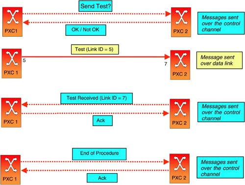
In this procedure, all messages other than “test” messages are sent over the control channel. Figure 6-25 illustrates this procedure for a pair of PXCs. Now, let us look at some of the details.
Figure 6-25. Neighbor Discovery with PXCs
Test Messages
What does a “test” message contain? It should at least have the local interface id of the link over which the message is sent. In addition, it may have the Node ID of the sending PXC, but the same information is also available in the request sent in Step 2 above.
The “test” message can be transported in many ways. With SONET/SDH framing, it can be sent as a string or an IP packet on overhead bytes as described earlier. Another possibility is that the test message is transported as the SONET/SDH payload. If this is the method chosen, then the Packet-over-SONET [Malis+99] encapsulation mechanism defined for IP can be used (see Chapter 3).
Further details on the contents and usage of the test message can be found in [Lang+03a].
Other Messages
The other control messages required are as follows:
A request message from the OXC that is going to send “test” messages to the neighbor that must terminate the “test” messages (Step 2). Under LMP, this message is called “Begin Verify”.
A response from the neighbor to the OXC sending the request (Step b). Under LMP, these messages are called “Begin Verify Ack/Nack.”
A message from the neighbor to confirm the receipt of test messages (Step f). LMP defines the “Test Status Success” message for this. Additionally, LMP also defines the “Test Status Failure” message to indicate that test messages were not received by the neighbor.
A message from the OXC sending test message to indicate the completion of link identification procedure (Step 7). The corresponding LMP message is called “End Verify.”
As noted before, all these messages are sent over the out-of-fiber control channel.
Execution of the Neighbor Discovery Procedure
The description of the neighbor discovery procedure above was very informal and high level. In reality, a number of issues must be addressed in defining an actual protocol. These include:
How often should test messages be sent in Step 4?
How long should a PXC wait to receive a response from the neighbor in Step 4?
Similarly, how long should the neighbor wait to receive a test message in Step c?
What happens when two neighboring PXCs simultaneously initiate the test procedure?
What happens when a PXC initiates the test procedure, but the neighbor does not want to participate in it?
Given that the test procedure actually uses a topological link, it cannot be used when the link is carrying traffic. Then, at what instances should an PXC initiate the test procedure?
The answers to questions 1–3 depends on the time it takes to set up cross-connects in the PXC and the number of links between neighbors. These parameters should be configurable in a protocol.
When two PXCs simultaneously initiate the test procedure, one of them must defer to the other based on some rule. For instance, the PXC with the numerically lower Node ID could defer to the other. If a PXC initiates the test procedure but the neighbor rejects it, then the PXC may wait for some time before initiating the procedure again. The waiting time must be specified in a protocol. Finally, the test procedure should be initiated whenever a link is newly configured, before any user traffic is routed over it. Furthermore, the test procedure must also be initiated when a link recovers from a failure event. This means that it should be possible to do link identification selectively for a set of links rather than the entire set of links to a neighbor. Readers interested in the protocol aspects are referred to the LMP specification [Lang+03a], although this document does not provide answers to all these questions.
6.4.3.3. COMPLEXITY OF COMPLETE LINK IDENTIFICATION
Complete link identification means that a PXC can automatically determine both the Node ID of the neighbor at the other end of a link as well as the remote interface id. The procedures described above were based on the assumption that the remote Node ID was known a priori. Consider the case when this is not true. Then, two problems arise. To completely identify a link, a PXC must potentially interact with all its neighbors since any one of them could be terminating the link on the remote end. Second, a neighbor participating in the test procedure must potentially look for test messages on all the candidate links (rather than only the subset that are connected to the PXC sending test messages). Other than just the delay this introduces (especially when PXCs support hundreds or thousands of ports), there is protocol complexity. As per the configuration depicted in Figure 6-24, as long as a PXC is engaged in a test procedure with one neighbor, it cannot do the same with another. If different PXCs are initiating the procedure for different links at the same time, the convergence of all these toward the identification of all links becomes an issue. Indeed, the same issue arises even when remote Node IDs are configured, and the link identification procedure described earlier is followed. But this problem is aggravated when the remote Node IDs are not known. As of present date, there is no satisfactory solution to the problem of complete identification of transparent links.
6.4.3.4. LINK PROPERTY CORRELATION
Link property correlation is done using the same messages exchanged over the control channel as described in section 6.4.2.3. This procedure with PXCs is no different than the one described for OXCs. Therefore, we will not describe this any further here.