
4.4. Mesh Restoration
The previous sections described two fundamental protection concepts, that is, linear protection and ring protection. In the course of this, it was seen that specific techniques were applicable to general mesh connected networks, that is, virtual 1:N SNC protection, software-defined BLSR, and p-cycles. In this section, mesh network based restoration is described. With mesh restoration, connections are not individually protected, but adequate bandwidth is provisioned in the network to reroute connections in the event of failures. This type of restoration is natural to consider in newer mesh networks with a distributed control plane. In the following, we first examine the potential bandwidth efficiency of in mesh restoration. Following this, an example of mesh restoration is presented.
4.4.1. Bandwidth Efficiency of Mesh Restoration
Mesh restoration techniques, or more properly restoration techniques applicable to mesh networks, are frequently touted as being bandwidth efficient especially with respect to rings. What is the basis for this claim? Is it always true? Is there a limit on how efficient a mesh restoration technique can be? In this section, we attempt to answer these questions.
First, the relevant terminology should be introduced. Specifically, a span between two network elements is defined as the fundamental failure unit. The span may be composed of many “links.” Note that the spans correspond to the units of “diversity” and the links correspond to the increments of bandwidth. For example, in SONET there could be a single OC-48 span and the “link” being the unit of bandwidth that we are protecting during a span failure (e.g., STS-1 channels).
Certain properties of the graph describing the communications network of interest must be considered. In such a graph, the switching systems are the vertices and the communication spans are the edges. This is shown in Figure 4-23.
Figure 4-23. Graph Representation of a Communications Network
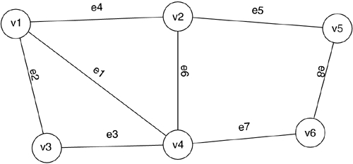
The degree, d, of a vertex is defined as the number of edges incident on that vertex. For example, in the graph depicted in Figure 4-23, vertex v4 has 4 incident edges and, hence, has a degree of 4, while vertex v5 has a degree of 2. The degree of a graph, G, can be defined as being the average of the degree of all the vertices within the graph G. The degree of the graph shown in Figure 4-23 is 16/6 = 2.667.
To determine a lower bound on the amount of bandwidth required to support mesh restoration, the first step is to specify under which fault conditions connections are completely restorable. The most common criterion is known as “one line out” restorability. This indicates that recovery is possible from any single span failure. Considering what happens at a single vertex of degree d, as shown in Figure 4-24, a lower bound can be obtained. In particular, at this vertex, one of the d spans carrying traffic has had a failure. This implies that possibly all the other traffic coming and/or going to this vertex through this failed span must travel over the other spans entering the vertex. Hence, if this load is split among the other spans, then on average 1/(d-1) of extra bandwidth has to be reserved on each of these spans to allow for restoration. Now, extending this idea to the entire graph, a reasonable lower bound on required spare capacity for mesh restoration is 1/(d(g)-1) where d(g) is the degree of the graph.
Figure 4-24. Vertex of Degree d with a Failure on One of the Spans

Considering SONET/SDH ring networks, the degree of each vertex is 2 and hence the degree of the graph representing the ring network is 2. The above bound indicates that a ring requires a protection bandwidth capacity equal to 100 percent of its working bandwidth. This is indeed the bandwidth that was set aside for protection in a 2/4F-BLSR. For the network of 4-23, a lower bound of 60 percent of its working bandwidth is required for protection, that is, this network does not have a good mesh structure. Hence, it is seen from this bound that mesh networks can require significantly less bandwidth to be set aside for protection. The amount required, however, is first dependent on the network topology and second on how the working and protection bandwidth is allocated across the network. Note that the bandwidth savings comes from sharing the unused (protection) capacity throughout the network and was made subject to the “one line out” assumption previously discussed.
4.4.2. End-to-End Source Rerouted Mesh Restoration
For the highest reliability, robustness, and bandwidth efficiency, a distributed, end-to-end (source) rerouted restoration scheme is difficult to beat. Such a method operates at the bandwidth granularity of the users' connections and therefore provides the highest bandwidth efficiency. End-to-end source rerouting can restore the maximum number of connections regardless of the type and extent of the network fault, that is, if there is a way to reestablish a connection within the bandwidth constraints of the network, the source rerouting technique will do it.
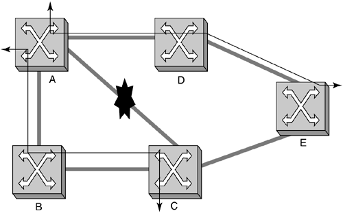
A simple example of connections being mesh-restored is illustrated in Figure 4-25 and Figure 4-26. In Figure 4-25, there are two connections, (A, C) and (A, E) that both traverse the same link, A-C, between nodes A and C. In Figure 4-26, the result of source re-route protection when link A-C fails is shown. Notice how the two connections can take different routes around the failure. This is the result of the fine granularity, connection-level restoration action.
Figure 4-25. Mesh Network with Two Connections
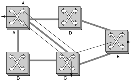
Figure 4-26. Source Rerouted Mesh Restoration to Recover from a Fiber Cut
Source rerouted mesh restoration is built on top of optical signaling and routing protocols. The routing protocol is responsible for distributing network topology and status information to the network nodes (switches). The signaling protocol allows the rapid establishment of end-to-end connections.
Table 4-12 reviews the characteristic of source rerouted mesh restoration in terms of the criteria discussed in section 4.1.2.
| Factor | Design Choice |
|---|---|
| Failure types that are restorable | Any restorable failure type, e.g., multiple lines, multiple nodes, network partitioning, etc. |
| Distributed vs. Centralized restoration | Completely distributed restoration for maximum robustness |
| Interoperability with other protection and automated provisioning | Interoperable with 1+1, 1:N and BLSR line protection schemes |
| Implementation complexity | Uses much of the infrastructure needed for rapid provisioning |