
8.5. Discussion
8.5.1. Performance Aspects and MPLS Fast Reroute
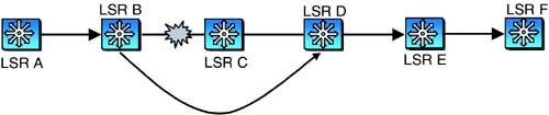
How fast can a protection scheme be if implemented using GMPLS signaling? Note that the bit-oriented protection protocols have the advantage of speed. There is no higher-level protocol processing, and message propagation through intermediate NEs is very quick. The corresponding delay measures for GMPLS signaling have not been highlighted by any study as of this writing. It has, however, been shown that LSP protection in MPLS networks using a feature called “fast reroute” can be accomplished within 50 ms time limit. Thus, an association is sometimes made between MPLS fast reroute and GMPLS-based protection in optical networks to imply that the latter can be responsive too. MPLS fast reroute, however, is not the same as protection in optical networks. Our objective in this section is to describe the distinction. The following descriptions are based on work in progress at the IETF [Pan+03].
As described in [Pan+03], MPLS fast reroute primarily provides “local repair” functionality. Local repair is illustrated in Figure 8-8. Here, the primary LSP is established from LSR A to LSR F, along the path A-B-C-D-E-F. At each LSR, a “detour” LSP is established to bypass the next hop LSR. Thus, a detour LSP connects LSR A to LSR C, LSR B to LSR D, and so on. There may be intermediate nodes along the path of the detour LSP. This is not shown in the figure. A detour LSP starts at the source or intermediate LSR in the path and ends at another intermediate or destination LSR. The starting point is called the point of local repair (PLR), and the ending point is called the merging point (MP). As the name implies, the MP represents the point at which the detour LSP is “merged” with the primary LSP.
Figure 8-8. Detour LSPs

Suppose a link fails along the path of the primary LSP. The LSR immediately upstream of the link diverts the LSP traffic onto the detour LSP. The traffic thus bypasses the failed link and reaches the MP. The LSR at the merging point then forwards the traffic along the primary LSP. For instance, considering Figure 8-8, suppose the link B-C fails. LSR B, after detecting the failure, starts forwarding the LSP traffic over the detour LSP along the path B-D. This is shown in Figure 8-9. The same action can be achieved when a node failure occurs, since detour LSPs can bypass nodes along the primary LSP as shown in Figure 8-8.
Figure 8-9. Rerouting after Failure of Link B-C
Detours can be established to protect individual LSPs or all the LSPs traversing a facility. The example in Figure 8-8 illustrates the former type of detour, also called one-to-one backup. A facility backup, on the other hand, is realized by establishing LSP tunnels with sufficient capacity between the PLR and the MP to accommodate traffic on all LSPs routed between the PLR and the MP along their primary paths. Figure 8-10 illustrates the case where there are two primary LSPs, one from LSR A to F (dotted line), another from LSR G to F (solid line). Both these LSPs traverse the common route from LSR A to LSR F. Each detour shown is a facility backup where the detour LSP tunnels protect both primary LSPs.
Figure 8-10. Facility Backup Example

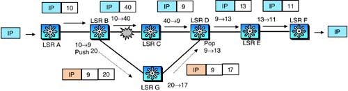
The manner in which protection is accomplished in the case of one-to-one backup is illustrated in Figure 8-11. As shown in the figure, the LSP route before the failure was A – B – C – D – E – F. An incoming packet is assigned a label 10 by LSR A. The label is switched from 10 to 40 by B, 40 to 9 by C, 9 to 13 by D, 13 to 11 by E, and finally the packet is delivered to the destination by F. When link B-C fails, LSR B immediately switches incoming packets toward LSR G, after switching the label from 10 to 20. LSR G switches the label from 20 to 17 before forwarding the packets to D. The alternate path and the labels to be assigned to incoming packets are preconfigured. At D, the packets are assigned a label 13 and forwarded to E as before.
Figure 8-11. Label Switching with One-to-One Backup

Figure 8-12 illustrates label switching under the facility backup case. Here, a detour LSP tunnel is preprovisioned along the path B-G-D. This tunnel can carry traffic on multiple “inner” LSPs. As before, packets along an LSP before the failure event are shown on top. After link B-C fails, the traffic is diverted onto the detour LSP tunnel. This is done using MPLS label stacking (see section 5.4.1). LSR B switches the incoming label (10) to the label that would have been seen by LSR D along the primary path (i.e., 9). LSR B also pushes a new top-level label, 20, corresponding to the detour LSP tunnel. Note that for other LSPs traversing the path B – C – D, LSR B would switch incoming labels to the values expected at D and push the same top-level label, 20. At LSR G, the top-level label is switched from 20 to 17. Finally, at D, the top-level label is popped to expose the original label placed by B, that is, 9. From here on, D switches the packet as if it arrived on the primary path.
From the descriptions above, it is clear that there is no internode signaling involved to effect LSP local repair. All the information needed to establish the alternate path is preconfigured. The RSVP-TE signaling for provisioning detour LSPs is described in [Pan+03]. We will not get into the details of this, but just note here that the signaling is somewhat complex. This is because a single primary LSP requires the establishment of multiple detour LSPs, and depending on the topology of the network, the detours have to be merged appropriately. The interested reader can refer to [Pan+03].
The detour LSP concept can be extended to provide complete end-to-end detour. This aspect is not covered in [Pan+03], but illustrated in Figure 8-13. Here, the primary LSP between LSRs A and F is routed as in the previous examples. A node-disjoint detour is established along the path A – G – H – I – F. When a failure occurs on the link C – D, a Notify message is sent by C to the source, that is, LSR A. LSR A then immediately switches traffic along the detour LSP as shown. Because MPLS LSPs are unidirectional, this procedure is simplified. As compared with the previous examples, the addition here is the use of the Notify message.

In summary, MPLS fast reroute based on local repair may not require any signaling during protection switching if the underlying link layer provides an upstream notification mechanism (e.g., RDI-L, see Chapter 3). Otherwise, a notification mechanism is required. End-to-end detour does require a notification mechanism, but it does not require the establishment of LSP mappings dynamically after a failure event. Furthermore, none of these protection mechanisms require coordination between the end nodes. In contrast, bidirectional 1 + 1 protection in optical networks requires a failure indication mechanism and end-to-end coordination. In addition, shared mesh protection requires the dynamic establishment of cross-connections at intermediate nodes. Thus, it is not meaningful to directly extrapolate performance observed in MPLS networks to optical networks even if a common protocol base (e.g., RSVP-TE) is used.
8.5.2. Restoration
We have focused on protection so far in this chapter. We stated in the introduction that restoration is tantamount to reprovisioning. The implication was that restoring a connection requires the same signaling procedures used during provisioning. Although this is largely true, certain issues that arise with restoration must be highlighted. First, the time to provision a connection is not as critical as the time to restore. This has some repercussions. Consider an optical network in which distributed routing is used. Suppose a failure affects a number of connections with different sources. Each of these sources will concurrently attempt to restore the connection along different paths. Because of the distributed routing, the view of the network resources at these source nodes may become temporarily out of date due to the restoration activity.
This is illustrated in Figure 8-14. Here, there are two connections, one from node A to node G, and another from node B to node H. The latter is indicated by dotted lines. Suppose there is a failure that affects both links between nodes D and G. From the figure, it can be seen that both connections will have to be restored. Suppose the routing information at nodes A and B indicate the availability of link E – G. Then, it is possible that A chooses the path A – E – G, while B chooses the path B – E – G – H. Assuming that only one of these connections can be accommodated on the link E – G, the route computed for the other connection is not correct. Because of the need to complete restoration quickly, an alternate detour path has to be dynamically computed. This requires crank-back procedures (see PNNI signaling in Chapter 7). Referring to Figure 8-14 again, suppose the connection from B to H is routed over the link E – G. The connection from A to G is cranked back to node A and the alternate detour path A – C – I – G is chosen. In contrast to restoration, if a provisioning request does not succeed in a network with distributed routing, the connection can be provisioned a little later after the routing information stabilizes.
Figure 8-14. Restoration Example

Second, a network that relies entirely on restoration requires a mechanism for reoptimizing connection routing periodically. To see this, consider the example in Figure 8-14 again. The initial path for connection from A to G was A – D – G, and the restoration path was A – C – I – G. Suppose the failed links between D and G is repaired. This makes the better path available once again, to which the connection can be moved. This is similar to reversion in protection switching, but it may be implemented as part of a global reoptimization process.
Finally, restoration requires a fast notification mechanism to indicate failures along the path of a connection to the source. Where such notification is available from the SONET/SDH layer, this is not an issue, but the messaging described in earlier sections will be required otherwise.