
5.2. Control Plane Architecture and Functional Model
To describe the architecture of the control plane, it is useful to first consider the functional structure of an optical network. From both a control and transport point of view, an optical network consists of layers and partitions. Layering is inherent in SONET/SDH technology and optical transport. This layering was described in Chapter 2, where it was shown that SONET (for instance) has Path, Line, and Section layers. Figure 5-2 illustrates equipment that operate at different layers. For example, the WDM equipment shown in the figure terminates the section layer overhead, the OXCs shown are line and section terminating, and the routers terminate path, line, and section overheads. Layering implies a client-server abstraction whereby the layer below provides a specific service to the layer above while hiding the details of implementation of the service. For instance, Path-Terminating Equipment (PTE) at the edges of the optical network (e.g., the routers in Figure 5-1) receive path layer connectivity from the collection of equipment operating at lower layers (e.g., the optical network in Figure 5-1). The PTEs need not be aware of how switching and transmission happens at the line and section layers. Similarly, adjacent line terminating equipment (LTE, e.g., the OXCs in Figure 5-2) are connected to each other through section layer equipment without being aware of the precise operation of the section layer. Thus, when we refer to the “control plane,” it is often associated with a specific layer. The focus in this book is on the control of the switching layer in optical networks. The mechanisms described in this book address both the control of OXCs (e.g., SONET/SDH cross-connects), and the control of PXCs that transparently switch wavelengths (see Chapter 1). Because of the similarities of the control issues in the optical switching layer to those in ATM, IP and MPLS networks, the control plane mechanisms developed for these networks can be adapted for use in optical networks. The rest of this chapter and the book are indeed devoted to describing these mechanisms.
Now, partitioning, as the name implies, is concerned with the division of a network into smaller parts for administrative, scalability, or other reasons. Two types of partitioning are possible. The first is topological partitioning whereby a large network is partitioned into multiple smaller networks (called subnetworks) for scalability reasons. The second is control partitioning whereby a large network is divided into multiple control domains, where each control domain defines specific control and/or management procedures for a part of the network. Both topological and control partitioning can be recursive, that is, a partition can itself be partitioned, and so on.
It is important to recognize the relationship between topological and control partitioning. Topological partitioning is typically used to improve the scalability of control procedures within a single control domain. Within a topological partition, homogeneous control procedures are implemented in all the subnetworks. An example of this is a large ATM network running the P-NNI protocols, whose topology is split into P-NNI peer groups (see section 5.6 and Chapter 7). Control partitioning, on the other hand, typically occurs when a network has to be partitioned on the basis of administrative or other criteria. For instance, a network may contain islands of equipment from different vendors with differing control and/or management procedures. In this case, the network may have to be partitioned into multiple control domains. Topological partitioning may be used within each control domain for scalability. Control plane procedures within a single control domain are referred to as intradomain procedures. These include signaling and routing procedures as described in Chapters 7–10. More challenging, however, are interdomain procedures for integrating individual, potentially disparate, control domains to build a unified, end-to-end control architecture. This is the subject of Chapter 12.
Both layering and partitioning, as well as the functional components and requirements of the control plane, have been formalized by ITU-T in a series of recommendations. In the following, a brief overview of the ITU-T models is given.
5.2.1. Network Model and Layering
ITU-T recommendation G.805 describes the “generic functional architecture of transport networks” [ITU-T00d]. This recommendation describes the architectural components, as well as the layering concepts, independent of the underlying networking technology. Figure 5-3 illustrates the functional model of the network as per G.805. This figure illustrates several architectural components. These can be broadly classified into:
Topological components, which include access points (AP), layer networks, links and subnetworks.
Transport entities, which include link connections (LC), subnetwork connections (SNC), network connections and trails.
Transport processing functions, which include adaptation and trail termination.
Figure 5-3. Transport Network Functional Model per [ITU-T00d]

These components are described below.
5.2.1.1. CLIENT AND SERVER LAYER NETWORKS
A layer network is defined by the set of capabilities available for transferring information specific to that layer (called characteristic information). For example, an IP network is a layer network, with IP packets being the characteristic information. A layer network could be a client or a server network in relation to another layer network. The connectivity between elements in a client layer network, and hence its topology, is established by utilizing connectivity provided by the server layer network. For instance, an IP network could be the client layer network utilizing connectivity services from an optical (server layer) network (Figure 5-1).
The client-server relationship may be applied recursively, that is, a server layer network may itself be a client layer for another server layer network. Figure 5-4 illustrates this in an SDH network. Here, the higher order path (HOP) layer network serves the lower order path (LOP) layer client, which in turn serves ATM and PDH clients. The client layer characteristic information is also illustrated.
Figure 5-4. Client and Server Layer Networks (from [ITU-T00d])

5.2.1.2. SUBNETWORK
A subnetwork exists within a single layer network. It is defined by the set of network elements that are members of the subnetwork, and the set of ports that are available for transferring information specific to the layer network. Connectivity between subnetworks within a layer network occur by interconnecting the ports. The subnetwork definition is recursive: a subnetwork may itself contain other subnetworks. By this definition, a single network element (or switching matrix) can be a subnetwork. In Figure 5-3, the ellipses at the bottom of the figure denote (server layer) subnetworks.
5.2.1.3. LINK
A link represents the topological relationship and available transport capacity between a pair of subnetworks. In the simplest case, a link connects a pair of ports in two network elements. An example is an OC-192 link between two optical switches. In the general case, a compound link may connect multiple ports in one subnetwork with corresponding ports in another subnetwork.[1]
[1] Such a compound link is called a traffic engineering link or TE-link in MPLS, see Chapter 10.
5.2.1.4. LINK CONNECTION
A link connection (LC) transfers information transparently across a link without monitoring the integrity of the transfer. It is delimited by a port at each end. A link connection in the client layer represents a pair of adap-tation functions and a trail in the server layer. For example, considering Figure 5-2, an STS-48c path layer trail in the optical network will be con-sidered a link connection between the IP routers (in the IP client layer). A pair of associated unidirectional link connections provide bidirectional in-formation transfer between the corresponding end points. The source and sink reference points of the link connection are referred to as Connection Points (CP, see Figure 5-3).
5.2.1.5. SUBNETWORK CONNECTION
A subnetwork connection (SNC) transfers information transparently across a subnetwork without monitoring the integrity of the transfer. It is delimited by ports at the boundary of the subnetwork and represents the association between these ports. Consider now a subnetwork that may itself contain other smaller subnetworks. A connection in this subnetwork is constructed from a concatenation of connections across the included subnetworks, and link connections between the included subnetworks. From the control plane point of view, an SNC represents a part of the end-to-end connection that may be established independently within a subnetwork.
5.2.1.6. NETWORK CONNECTION
A network connection is an end-to-end connection across a layer network, delimited by Termination Connection Points (TCPs). It is formed by concatenating subnetwork connections and/or link connections. There is no explicit information to allow the integrity of the transferred information to be monitored. As an example, an STS-1 network connection would consist of concatenated STS-1 subnetwork and/or link connections spanning multiple switches.
5.2.1.7. TRAIL
A trail represents the transfer of monitored, adapted characteristic information of the client layer network between access points. For example, the optical network in Figure 5-2 may provide an STS-48c path layer trail between the two end clients (e.g., IP routers). A trail is delimited by a trail termination point at each end.
A trail in the server layer could be a link connection in the client layer. Continuing the earlier example, the STS-48c path layer trail provided by the optical network in Figure 5-1 will appear as a link connection in the IP layer between the two IP routers. If the client layer is itself a server layer for some other client layer, this definition continues.
From a control plane point of view, the request to create a trail from a client layer entity results in the creation of a trail in the server layer and the establishment of the appropriate adaptations in the end points of the trail. Thus, when we loosely say that an STS-48c (link) connection is established between two routers, it means that an STS-48c path layer trail is created in the optical network. Furthermore, an appropriate mapping of the IP payload and other path layer functions are established in the routers.
5.2.1.8. ADAPTATION FUNCTION
Adaptation refers to the process whereby characteristic information in the client layer is mapped onto a form suitable for transport over a trail in the server layer network and the recovery of the client layer information from the server layer trail. An adaptation source is the point where the client layer information is mapped on to the server layer trail, and the adaptation sink represents the point where the mapped information is recovered.
5.2.1.9. TRAIL TERMINATION FUNCTION
The trail termination function is defined by the following entities:
Trail termination source: A transport processing function that accepts adapted characteristic information from a client layer network at its input, adds information to allow the trail to be monitored, and presents the characteristic information of the server layer network at its output. An example of a trail termination function at the source is the addition of BIP-8 code for performance monitoring of the trail, as described in Chapter 3.
Trail termination sink: A transport processing function that accepts the characteristic information of the server layer network at its input, removes the information related to trail monitoring, and presents the remaining information at its output. An example of a trail termination function at the sink is the use of BIP-8 information added at the source to calculate the bit error rate of the trail.
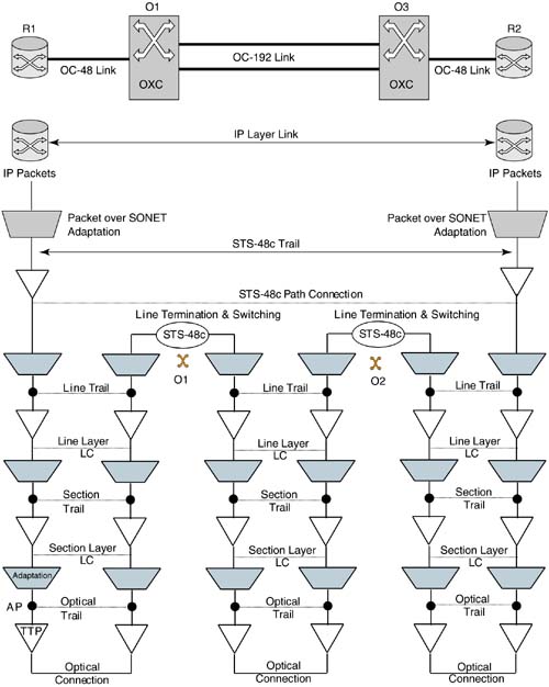
The above concepts are illustrated using a practical example in Figure 5-5. Here, two routers interconnected via an optical network are shown. The optical switches have OC-192 links between them. The routers have OC-48 links to the optical switches. A link connection at the IP layer has to be established between the two routers. This link connection is realized as shown, over an STS-48c path layer trail. This trail in turn is realized over the underlying line and section layers as shown. Connections and trail shown are assumed to be bidirectional. Various access points (AP), trail termination points (TTP) and adaptation functions are shown.
5.2.2. Partitioning and Control Interfaces
Topological and control partitioning were described earlier. Figure 5-6 illustrates partitioning of a large network. In this figure, each large oval represents a control domain, which is topologically partitioned into multiple subnetworks as shown. The links shown are abstractions of actual physical links between network elements (see Chapter 12).
Figure 5-6. Partitioning of a Large Network (from [ITU-T00d])

In addition to network partitioning, links may be aggregated or partitioned. In the definition of a link in section 5.2.1.3, a compound link was described as a collection of several simple links. The aggregation of simple links is called link bundling. A simple link in a bundle is also referred to as a component link. A bundled (compound) link may itself be a component link in another bundle. Thus, bundling could be recursive. The levels of bundling depend on how various link properties are represented in the control plane. Figure 5-7 illustrates a compound link and the constituent component links between two subnetworks. Link bundling is further described in Chapter 10.
Figure 5-7. Link Bundling

From a control plane point of view, a partitioned network presents certain requirements. First, the control procedures within different control domains may not be the same. This could especially be the case in a multivendor network. A unified control plane spanning the entire network must therefore accommodate heterogeneous control domains. The ultimate goal, of course, is to be able to provision and maintain network connections across multiple control domains.
Second, the scope of the overall control plane must be carefully defined. The notion of a “standard” control plane is to facilitate interoperability between multivendor equipment. But at what points in the network that interoperable procedures are required must be determined.
Finally, the implementation of a control plane requires information transfer between entities that participate in the control process. Partitioning invariably results in the curtailment of the information flow across control domain and subnetwork boundaries. This is also referred to as information abstraction. The precise mechanics of information abstraction determine the characteristics of the control plane procedures, and hence must be determined carefully.
Figure 5-8 illustrates the commonly accepted view of control interfaces in a network. Two optical networks, administered by different service providers, are shown in this figure. Each optical network is partitioned into control domains as shown, and two client networks connecting to the optical network are shown. The control interfaces shown are:
The User-Network Interface (UNI): This is the control interface between a node in the client network and a node in the optical network.
The Interior Network-Network Interface (I-NNI): This is the control interface between two subnetworks (or nodes) within the same control domain.
The Exterior Network-Network (E-NNI): This is the control interface between two nodes in different control domains. This definition does not distinguish between the case where the control domains are administered by the same service provider and the case where the control domains are administered by different service providers. As a result, such a distinction, where necessary, must be made explicitly.
Figure 5-8. Control Plane Interfaces
The control interfaces in Figure 5-8 indicate the points where control plane interactions occur. An issue is whether the control plane functionality must be present in the network elements themselves. Typically, this is the case in IP networks, where the routing and the signaling protocols are implemented directly in the routers. In the case of optical networks, however, the control functionality can be distinct from the transport functionality. Indeed, the control plane functionality may be implemented outside of the network elements by a proxy agent. Figure 5-9 illustrates the generic control plane abstraction, where the control “agents” depicted can be either built into or physically separate from the network elements. In the latter case, a single control agent can represent multiple network elements. The (internal) interface between the network elements and control agents need not be standardized.
Figure 5-9. Control Plane Abstraction

Whether or not the control functionality is integrated with the network elements, a function that can only be executed over the transport links between the network elements is neighbor discovery. This is described next. Also, the connectivity shown in Figure 5-9 between the control agents defines the control plane adjacency. Two adjacent control plane agents, in reality, do not necessarily need direct physical connectivity. The only requirement is reachability between adjacent control agents. A data communication network (DCN), which in the simple case could be a direct physical link, provides this reachability.
5.2.3. Control Plane Functions
The main control plane functions are summarized below. They are covered in greater detail in the following chapters.
Neighbor discovery: In simple terms, neighbor discovery is a function whereby a network element automatically determines the details of its connectivity to all its data plane neighbors. These details include the identity of the neighbors, the identity of the link terminations, and so on. Neighbor discovery applies to both the UNI and the NNI shown in Figure 5-8, and it is the subject of Chapter 6.
Routing: Routing broadly covers two control aspects. The first is automatic topology and resource discovery. The second is path computation. The first capability allows each control agent to determine the data plane connectivity and resource availability in the entire network. This procedure typically relies on a mechanism to propagate link connectivity and resource information from one control agent to all others in the network. What information is propagated and how the information is represented at each control agent depend on the type of routing scheme. Various routing schemes are described in Chapters 9, 10, and 12. Path computation is a procedure whereby a control agent determines a path for a connection using the available topology and resource information. Path computation algorithms are described in Chapter 11.
Signaling: Signaling denotes the syntax and the semantics of communication between control agents in establishing and maintaining connections. Signaling involves the use of standard communication protocols across the UNI and the NNI, and these procedures are described in Chapters 7 and 8.
Local resource management: This refers to the representation and accounting of locally available resources controlled by a control agent. Concise resource representation is essential for the scalability of routing mechanisms. Local resource management aspects are covered in Chapter 10.
5.2.4. The Data Communications Network
The data communications network (DCN) refers to the communication infrastructure used for messaging between control agents in an optical network. The DCN may also be used to provide connectivity between the control agents and element or network management systems (see Chapter 13). Typically, control communication is packet oriented (e.g., using TCP/IP). Thus, the DCN is typically packet based (e.g., IP) over an underlying network technology (e.g., ATM). The DCN therefore provides network layer (OSI Layer 3 [Stallings03]) connectivity between control entities in an optical network. Under the partitioning paradigm shown in Figures 5-6 and 5-8, control communication may happen at several levels. For instance, communication is required between control entities in different control domains as well as control entities within the same control domain. The network infrastructure for interconnecting control agents across subnetworks could potentially be different than the one used within a subnetwork. The term DCN, however, will be used to refer to the overall network infrastructure for control communication.
The main issues with regard to the design of a DCN are:
Network layer protocol used: Since the DCN provides network layer connectivity, a specific network layer protocol (and technology) must be selected. From a practical perspective, the choices today are IP version 4, IP version 6, or OSI Connection-Less Network Protocol (CLNP). A DCN may support more than one network layer (e.g., CLNP and IP) with built-in gateway functionality.
Network infrastructure: The main choice with regard to the network infrastructure (upon which the DCN is built) is whether the network is associated with the optical data plane. With SONET or SDH data plane, certain overhead bytes can be used to realize packet communication between control elements. In this case, the DCN network infrastructure is said to be realized in-fiber. On the other hand, a separate network technology not associated with the optical data plane can be used to realize the DCN. For example, an external IP network can be used. In this case, the DCN is said to be realized out-of-fiber. As mentioned earlier, a DCN could comprise of different parts that are interconnected, for instance, an in-fiber part in one subnetwork and an out-of-fiber part external to that subnetwork.
Application requirements: The DCN may support multiple applications, such as signaling, routing, and communication with management systems. These applications may pose certain requirements on the DCN, such as latency, packet loss, security, and so on. In general, the DCN must support low latency and low packet loss. In addition, the DCN must be secure and not be vulnerable to external interference.
ITU-T recommendation G.7712 [ITU-T01c] describes the general architectural aspects of the DCN. The specific details of in-fiber versus out-of-fiber realization of the DCN are discussed in Chapter 6. In the following, the control plane aspects in IP, MPLS, and ATM networks are briefly described.