
5.6. Control of ATM Networks: The P-NNI Protocols
In ATM networks, Virtual Circuits (VCs) provide connectivity between two ATM end points. An ATM VC is a logical circuit with associated bandwidth, delay, and other service parameters. The P-NNI protocols, described next, provide the routing and signaling capabilities required for establishing and deleting VCs. It is quite feasible to adapt these protocols for use in optical networks, and hence it is instructive to look into their details.
5.6.1. The P-NNI Hierarchy
Private Network-Network Interface (P-NNI) denotes both the interface between border switches in two ATM subnetworks as well as the interface between two switches within a network.[3] The ATM Forum P-NNI specification defines automated routing and signaling procedures across these interfaces to aid in connection provisioning [ATMF02].
[3] In essence, what this means is that the procedures defined for the network-network interface can also be used at the node-node interface. The term P-NNI is used to denote both these interfaces.
Both P-NNI routing and signaling support a multilevel hierarchical network structure. The notion of a peer group is used under P-NNI to describe this hierarchical structure. At the lowest level, a peer group consists of a collection of individual nodes. Two or more such lowest level peer groups can be grouped to form the next higher level peer group and so on. Each peer group is distinguished by its level and its identifier. Figure 5-15 illustrates the hierarchical organization of a sample network. This network has 23 nodes interconnected as shown. Six first-level peer groups are formed, with identities A.1–A.4 and B.1–B.2. These peer groups are shown enclosed in dotted boxes. In each peer group, a node is elected as the peer group leader. The peer group leader can be any node in the peer group. In the figure, the peer group leaders are shown shaded. Each level of the hierarchy is identified with a “level” number. This is explained in the next section. Each node in the network has an associated identifier. For the moment, let us assume that the numbers 1–23 indicated in the figure are the node identifiers. The actual formats of the node and peer group identifiers are described in the next section.
Figure 5-15. P-NNI Hierarchy
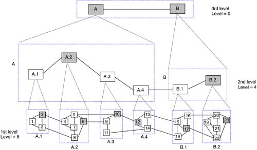
The connectivity between peer groups at the first level is defined by the physical links that interconnect border nodes. The second level peer group now consists of logical nodes (A.1–A.4, B.1–B.2) that represent the first level peer groups, along with logical links that capture the connectivity between the peer groups in the first level. Similarly, the third level peer group is formed containing two logical nodes, A and B, and a single logical link as shown.
Peer groups at various levels are formed through a combination of manual configuration and P-NNI routing intelligence. First, the network administrator must decide how to structure the network and assign the first level peer group identifier to each node. Taking the example of Figure 5-15, each of the 23 nodes is configured with its first level peer group identifier, that is, nodes 1–3 are configured with the identifier A.1, nodes 4–8 with A.2, and so on. Now, it can be seen that the second level peer group identifiers are a prefix of the first level identifier, that is, A is a prefix of A.1–A.4 and B is a prefix of B.1–B.2. This is not an accident. The peer group identifiers are structured in such a manner that two adjacent nodes in the network can determine the “lowest common” peer group to which they both belong. As an example, nodes 3 and 4 can compare their peer group identifiers and determine that they are both part of the next higher level peer group, A. Similarly, nodes 13 and 15 can determine that the lowest common peer group is the third level peer group. Thus, under P-NNI, the first level peer group identifier is configured in each node, and the rest of the structure is determined by the nodes themselves as part of P-NNI routing. This procedure is aided by the structure of the peer group identifier, as described in the next section.
The peer group leader in each peer group is responsible for importing and exporting information to/from the peer group to higher level peer groups. In essence, a peer group leader represents the logical node in the higher level peer group topology. The control plane adjacencies between logical nodes correspond to control channels between the corresponding peer group leaders. These control channels, called Routing Control Channels, are usually switched virtual circuits between peers, either adjacent physical nodes or logical nodes. As an example, consider Figure 5-15. Peer group leaders 3 and 6 represent logical nodes A.1 and A.2 in the higher level. There is a control channel between these nodes even though they are not physically adjacent in the topology. There is also a control channel between nodes 3 and 4 as they are adjacent.
Finally, P-NNI routing allows each node to build a “view” of the network topology. The procedures for this are rather involved, and the interested reader can refer to [ATMF02]. From a signaling point of view, it is important to know what the topology view at a node looks like. Considering node 1 in Figure 5-15, the view will contain:
The complete topology of peer group A.1. This consists of a representation of all the nodes, links, and the associated parameters (e.g., link metrics, node attributes, etc.).
The topology of interconnection between peer group A.1 and adjacent peer groups in the second level. This contains the logical nodes A.2–A.4, the interconnection between A.1 and A.2, and the logical links interconnecting A.2–A.4. As before, the topology information includes the relevant node and link parameters.
The topology of interconnection at the third level. This consists of logical node B and the logical link between A.4 and B, along with the associated parameters.
Figure 5-16 illustrates this topology view.
Figure 5-16. Topology View at Node 1

5.6.2. Addressing and Identification
Addressing and identification are two distinct concepts under P-NNI. Specifically, interfaces to end-systems (e.g., hosts) and other destinations of P-NNI signaling (e.g., node interfaces) have addresses. Nodes and peer groups have associated identifiers. Since P-NNI protocols are designed for ATM networks, the addressing supported is the ATM End-System Addresses, or AESA for short. The ATM Forum has defined four formats for AESA, all of them 20 bytes long [ATMF99]. The generic format of the AESA is shown in Figure 5-17a. From the point of view of P-NNI protocols, an AESA is taken simply to be a 20-byte (160-bit) number. Of this, the first 19 bytes (152 bits) are used for P-NNI routing and signaling, and the last byte (selector, SEL) is used for end-system selection at a destination node. Logical node identifiers, however, utilize the 6-byte End-System Identifier (ESI) field of the AESA.
Figure 5-17a. Generic Format of AESAs

Now, a prefix of a given AESA is a string of bits whose length n is less than 160 bits and which matches exactly the first n bits of the AESA. Figure 5-17b illustrates an AESA and a prefix that matches in the first 10 bytes (the rest of the prefix are set to 0). Here, each byte of the AESA is represented by two hexadecimal digits. An ATM node can be assigned a 19-byte prefix, and the node can then generate up to 256 AESAs by assigning different values to the last byte. Such node-generated AESAs can be assigned to end-systems. One of them can also be taken by the node as its identifier. To be able to establish connections, nodes and end-systems must have an address (AESA) assigned.
Figure 5-17b. An AESA and a 10-Byte Prefix

Now, a prefix of length n bits (n < 160) is said to summarize all AESAs whose first n bits are the same as the prefix. Summarization is the key to the scalability of P-NNI routing. The hierarchical structure of the network must be such that it should be possible to summarize the address of all the end-systems (and nodes) reachable inside any peer group with a few prefixes.
Each peer group is assigned an identifier. A peer group ID can be up to 13 bytes (104 bits) long. The format of the ID is shown in Figure 5-18. The level field shown indicates the length of the peer group ID in bits. When the level field contains a value n, the leftmost n bits of the identifier field contain the peer group ID. The rest of the bits (104 – n right most bits) are set to 0. A peer group ID with level = n is said to be a prefix of another peer group ID with level = m if n < m and the corresponding identifier fields match exactly in the leftmost n positions. This is similar to the concept of AESA prefixes. Looking at Figure 5-15 again. If we assume that the peer group IDs shown represent two hexadecimal digits (each 4 bits long), the level of peer group A.1 is 8 (8 bits total) and the level of peer group A is 4. The top level is assigned the value 0.
Figure 5-18. Format of Peer Group ID
A peer group whose identifier is a prefix of another peer group is said to be a parent of the latter. Thus, two adjacent nodes that are in peer groups at levels k and m, and whose identifiers match in the first n bits (n < k, m) can assume that they are part of a common parent peer group at level n. This can be illustrated using Figure 5-15. Considering nodes 3 and 4, their peer group identifiers are A.1 and A.2, respectively. Comparing the identifiers, they match in the first 4 bits (the hex digit “A”). Thus, the nodes are part of the same parent peer group “A” (whose level is 4). The peer group A, in fact, contains four logical nodes A.1–A.4 as shown in Figure 5-15. Similarly, considering nodes 13 and 15, their peer group IDs are A.4 and B.1, respectively. Thus, there is no match, and these nodes have a common parent peer group at the top-most level (i.e., level 0, the peer group containing A and B).
The P-NNI specification recommends that a peer group identifier be a prefix of the AESAs reachable within the peer group. There is, however, no requirement that there is a correlation between peer group identifiers and reachable addresses for the P-NNI procedures to work.
A node identifier is a 22-byte number with the following structure: a 1-bye level indicator followed by a 21-byte identifier field. The assignment of these values for physical and logical nodes is as follows:
For physical nodes, the level indicator contains the level of the node's immediately enclosing peer group. The first (left most) byte of the identifier field contains the value 160 (A0 in hex). The next 20 bytes contain an AESA of the node. The node identifier corresponding to node 1 in Figure 5-15 is shown in Figure 5-19a.
Figure 5-19a. Node ID of Node 1
For logical nodes, the level indicator contains the level of the node's immediately enclosing peer group. The first (left most) 14 bytes of the identifier field contain the ID of the lower level peer group to which the corresponding physical node belongs (note that logical nodes are represented by peer group leaders of a lower level peer group). The next six bytes contain the ESI of the physical node. The last byte is set to 0. The node identifier corresponding to logical node A.1 in Figure 7-38 is shown in Figure 5-19b.
Figure 5-19b. Node ID of Node A.1
Finally, a port identifier is a 32-bit number locally assigned by a node to each of its ports. A link (logical or physical) is identified by the pair, <node ID, port ID>, where node ID is the identity of the node at either end of the link and port ID is the identifier assigned by the node to the port to which the link attaches.
P-NNI signaling and routing are described further in Chapters 7 and 9, respectively.