12.4. Interdomain Routing
The only true domain-to-domain protocol in use in the Internet today is the BGP protocol. BGP usage is not predicated on the use of specific routing protocols within domains. For example, BGP is frequently used between domains running different and incompatible internal routing protocols (typically, OSPF or IS-IS). Unfortunately, BGP does not have mechanisms to deliver the topology and link status information that is important in computing routes in optical networks. Nor does it have mechanisms for dealing with multiple hierarchical levels. In this section, we examine how a hierarchical link state protocol can be used for interdomain (i.e., domain-to-domain) routing.
12.4.1. Routing Information Categorization
Different applications of interdomain optical routing call for different types of information to be shared between domains. We can broadly categorize this information into two categories: topology and resource information, and node and domain information.
12.4.1.1. TOPOLOGY AND RESOURCE INFORMATION
Under this category, the attributes associated with each link are:
Link identifier (typically, a pair of IDs, one for each end)
Available capacity
Other metrics
Protection and restoration support
Associated SRLG
A link may be interdomain (external) or intradomain (internal). It may correspond to a component link, a link bundle (TE link, see Chapter 10), or an abstract link.
Topology
The link identifier indicates the two ends of the link, typically the nodes that terminate the link. The SRLG parameter indicates the failure dependencies between links.
As discussed in Chapter 11, link attributes may be captured by administratively established metrics. A link may have more than one metric associated with it. The topology of the network is defined by the collection of links identified.
Link Capacity
The bandwidth accounting needed in optical networks is significantly different as compared with packet networks. In packet networks, for instance, with ATM or MPLS-TE, complex statistical measures are used to characterize the load on a link. These measures are not exact, but the “compressibility” of statistically multiplexed traffic minimizes the impact of small errors in characterization. By contrast, if an OC-192 link has just one STS-1 path occupied (less than 1% of the link bandwidth), it cannot accommodate an STS-192c path. Due to the relatively simple multiplex structures used, tracking bandwidth resources is much easier in optical networks than in packet switched networks. Much stricter bandwidth accounting, however, is required for optical links. For instance, while an individual optical link can be fully utilized, a packet link is typically run at less than full capacity to accommodate bursts. Such basic differences restrict the direct applicability of some of the packet network traffic engineering mechanisms in optical networks.
Although the multiplex structures in optical transport networks are fairly straightforward, there are a number of issues that prevent a single number from representing the available capacity on a fiber. For example, in a SONET system, it is not generally possible to represent the capacity at the STS path level by the number of empty STS-1 time slots on a line. This is due to the placement rules concerning STS-Nc, that is, concatenated signals (see Chapter 2). Instead, it is much easier to list the available capacity for each type of signal that may be carried on a link.
To illustrate this, consider Figure 12-10, which shows the time slots of an OC-48 line that is carrying a combination of STS-1, STS-3c, and STS-12c path-level signals. Under the rules of standard concatenation, this link can further accommodate 24 STS-1s, 6 STS-3cs, and no STS-12cs. Note how a single number cannot characterize the available capacity.
Figure 12-10. An OC-48 Link Carrying STS-1, STS-3c, and STS-12c Signals

We saw in Chapter 2 that a VC-3 signal can be used to carry a number of smaller-capacity signals known as lower order VCs (or virtual tributaries in SONET). These are multiplexed using an intermediate structure known as a TUG-2. A VC-3 can hold seven TUG-2s (see Chapter 2). A TUG-2 can only hold one type of signal, (VC-11, VC-12, VC-2), but in the case of VC-11 and VC-12, it can hold either 4 or 3 of these signals, respectively. As in the previous example, a better description than a single number is needed to capture the capacity. For example, consider a VC-3 that has 2 TUG-2s occupied with 2 VC-11s each, and 2 TUG-2 each with 1 VC-12, with the remaining TUG-2 unoccupied. We can easily and compactly represent the bandwidth available by indicating that the VC-3 has the capacity for 3 TUG-2s, 4 VC-11s, and 4 VC-12s. No single number, however, can represent the available capacity.
Underlying Protection
The protection features supported on a link are useful to characterize. For instance, such information could indicate whether the link is protected and, if so, the type of protection scheme (e.g., linear 1+1, linear 1:N, 4F-BLSR, etc.). This information can be used both in path selection and in advanced multilayer recovery methods (see Chapters 7 and 10).
12.4.1.2. DOMAIN AND NODE-RELATED INFORMATION
Reachability information indicates which end systems or network nodes are directly reachable from a particular domain. Suppose that in domain B of Figure 12-1, each of the network elements, NE1–NE3, is attached to end systems. Then, the addresses of all the attached end systems and those of the three NEs would form the reachability information for domain B.
Subnetwork capability information describes the capabilities or features offered by the domain as a whole. This information is used in applications where sharing the internal topology and resource information is inappropriate. This information can include (a) switching capabilities, (b) protection capabilities, (c) an overall available-capacity measure, and (d) reliability measures. For example:
In a SONET network, one subnetwork may switch at STS-3c granularity while another switches at STS-1 granularity. Understanding which types of signals within a SDH/SONET multiplex structure can be switched within a subnetwork is important.
Some networking technologies, particularly SONET/SDH, provide a wide range of standardized protection techniques, but not all domains may offer all the protection options. For example, a 2/4-F BLSR based subnetwork could support extra data traffic, ring protected traffic, and non-preemptable unprotected traffic (NUT), while a mesh network might offer shared, line layer linear protection and mesh protection.
Some domains may be in locations that have lower incidences of link failure. Such information could be helpful in computing routes to statistically “share the pain.”
Although properties of the subnetwork are very important for routing a connection, end systems also possess a wide variety of capabilities. Allowing end system capabilities (such as a system's ability to support SONET/SDH virtual concatenation) to be distributed into a routing protocol may not be advantageous though, since it may counter the ability to summarize reachability information. Detailed end-system information may alternatively be obtained using a directory service or some type of direct query between the end systems.
12.4.2. Routing within a Hierarchy
When a hierarchy of RAs is established, RCs must be configured at least with information that allows them to determine which RAs they belong to. The question arises, particularly from the operational context, as to how much information can flow automatically between different levels in a routing hierarchy.
In this section, we look at automation of information flow up and down the routing hierarchy. In the following section, we look at the role neighbor discovery (Chapter 6) can play in automating the routing configuration process.
12.4.2.1. ROUTING INFORMATION FLOW UP THE HIERARCHY
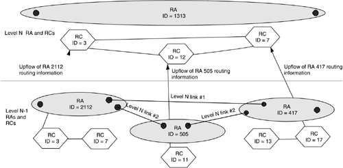
The primary entities of interest at level N of a routing hierarchy are the links between the RCDs (represented by the RCs) in that level and the reachable addresses within each RCD. The properties of an RCD are represented by the “nodal” properties of the corresponding RC. These are in turn derived from the corresponding level N-1 (next lower level) RA that the RCD represents. The links between level N-1 RAs are actually level N RA links (or higher) as shown in Figure 12-11. In addition, in some cases it may be very useful for an RC to offer some approximate representation of the internal topology of its corresponding RCD. Figure 12-11 shows information flow between RC 11 in RA 505 and RC 12 in RA 1313.
12.4.2.2. ROUTING INFORMATION FLOW DOWN THE HIERARCHY
An RC at a lower level of the hierarchy needs information pertaining to higher levels to be able to compute an end-to-end path. For example, RCs in RA 2112 need to know the interconnection between level N-1 RAs to be able to compute a path across these RAs. But this interconnection information is available only at level N. Thus, there is need for routing information to flow down the hierarchy. There are two approaches for realizing this flow.
In the path computation server approach, a higher-level RC is consulted to find an appropriate route between the source and the destination RAs. This would give a coarse route, that is, in terms of a list of RAs at a given level to be traversed. Under this approach, the contacted RC must belong to an RA within whose scope both the end points lie.
Instead of contacting an RC at another level, the higher-level topology information may be propagated downward to all the lower level RAs. Such an approach was taken in hierarchical PNNI routing [ATMF02] (see Chapter 9).

