
8.2. Span Protection
8.2.1. Functional Description
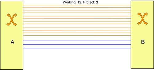
As described in Chapter 4, LAPS supports 1 + 1 and 1:N protection schemes. Under LAPS, 1:N protection requires the configuration of protection groups, that is, groups of N+1 links, where N links are designated as working links and 1 link as the protection link. This is shown in Figure 8-2a, where three protection groups between nodes A and B are shown. The 1:N protection scheme can be generalized into a M:N scheme, where there are N working links and M protection links, M < N. Thus, if a failure affects more than M working links in a protection group, only M of them can be protected even if there are free protection links in other groups. A further generalization of this scheme is to pool all protection links into a single group. That is, a protection link can protect any working link. This is shown in Figure 8-2b. In effect, this is similar to having a single M:N protection group, except that there is flexibility in choosing the values of M and N, and the ability to not preassign links as working or protection (if so desired). This type of protection can also be used with OOO NEs (i.e., PXCs) if failures can be localized.
Figure 8-2a. Protection Groups
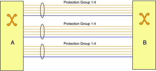
Figure 8-2b. Pooling of Protection Links
Considering two neighboring NEs A and B, the details of this protection scheme are as follows:
At any point in time, there are M+N links between A and B of which at most N links can be assigned to carry working traffic and at most M links can be assigned to carry protection traffic. A link is said to be “free” if it has no working or protection traffic on it, or it is carrying extra traffic that could be preempted.
When a working link is affected by a failure, the traffic on it is diverted to a free link provided that the total number of links being used for carrying protection traffic (referred to as protection links) is less than M. Note that the failed link could be carrying more than one connection, for example, an OC-192 link carrying four STS-48 link connections.
More than one working link may be affected by a failure event. In this case, there may not be an adequate number of free links to assign to protection traffic (i.e., the number of protection links exceeds M). The set of affected working links that are actually restored is then subject to policies (e.g., based on relative priority of working traffic).
Each node is assumed to have an identifier, called the Node ID. Each node is also assumed to have the mapping of its local link (or port) ID to the corresponding ID at the neighbor. This mapping could be manually configured, or obtained automatically using a neighbor discovery procedure (see Chapter 6). When traffic must be diverted from a failed working link to a free link, the decision as to which free link is chosen is always made by one of the nodes, A or B. To do this, the node with the numerically higher Node ID is considered the “master,” and it is required to both apply any policies and select specific free links to divert working traffic. The other node is considered the “slave.” The determination of the master and the slave may be based on manually configured information, or as a result of running a neighbor discovery procedure.
Failure events themselves may be detected using SONET/SDH mechanisms where applicable (see Chapter 3). Since a bidirectional link is realized using a pair of unidirectional links, a failure in the link from A to B is typically detected by B, and a failure in the opposite direction is detected by A. It is possible for a failure to simultaneously affect both directions of the bi-directional link. In this case, A and B will concurrently detect failures, in the B-to-A direction and in the A-to-B direction, respectively.
The basic steps in this span protection scheme are as follows:
1. | If the master detects a failure of a working link, it autonomously invokes a process to allocate a free link to protect the affected traffic. This process must take into account any policies in protecting working traffic and ensure that the total number of protection links does not exceed M. |
2. | If the slave detects a failure of a working link, it must inform the master of the failure. The master then invokes the same procedure as above to allocate a free link. (It is possible that the master has itself detected the same failure, for example, a failure simultaneously affecting both directions of a link.) |
3. | Once the master has determined the availability and the identity of the free link for carrying protection traffic, it indicates this to the slave and requests the switchover of the traffic. Prior to this, if the selected link was carrying extra traffic, the master stops using the link for this traffic (i.e., the traffic is not forwarded into or out of the link). |
4. | The slave sends an acknowledgment to the master. Prior to this, if the selected link was carrying traffic that could be preempted, the slave stops using the link for this traffic (i.e., the traffic is not forwarded into or out of the link). It then starts sending and receiving the (failed) working link traffic over the newly assigned protection link. |
5. | When the master receives the acknowledgment, it starts sending and receiving the (failed) working link traffic over the new protection link. |
It is clear from the description above that this span protection scheme may require up to three messages for each working link being switched: a failure indication message, a switchover request message, and a switchover response message. The functional requirements pertaining to these messages are as follows.
8.2.2. Messages
8.2.2.1. FAILURE INDICATION MESSAGE
This message is sent from the slave to the master to indicate the ID of one or more failed working links. The number of links included in the message would depend on the number of failures detected within a window of time by the sending node. A node may choose to send separate failure indication messages in the interest of completing the restoration for a given link within an implementation-dependent time constraint.
The ID of a failed link is the identification used by the slave node. The master must convert this to the corresponding local ID.
8.2.2.2. SWITCHOVER REQUEST MESSAGE
This message is sent from the master to the slave to indicate that the connections on the (failed) working link can be switched to an available free link. This message contains one or more entries of the form, <Protection link ID, Working link ID>, each indicating a newly assigned link to protect a failed working link. The IDs are based on the identification used by the master. The slave must convert them to the corresponding local IDs.
The master may not be able to find a free link to protect a failed working link. Thus, the set of restored links indicated in this message may be a subset of all failed links. Also, depending on time constraints, the master may switch the set of failed links in smaller batches. Thus, a failure event may result in the master sending more than one switchover request message to the slave node.
8.2.2.3. SWITCHOVER RESPONSE MESSAGE
This message is sent from the slave to the master to indicate the completion (or failure) of switchover at the slave. It contains the IDs of the new protection links that the slave has switched over to. In this message, the slave may also indicate that it cannot switch certain failed links to protection links (for unspecified reasons). The action to be taken by the master in this case is not explicitly defined (e.g., the master may abort the switchover of these links, and perhaps trigger end-to-end path protection for the affected connections).
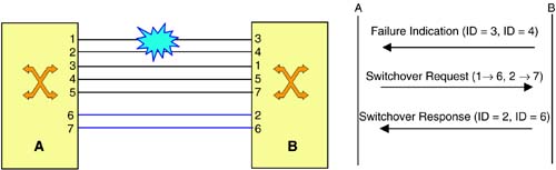
Figure 8-3 illustrates how this protection scheme works. Here, node A is the master and B is the slave. Also, M = 2 and N = 5, and the links have different identification on the two sides. A failure event affects links 3 and 4, as identified by node B, in the A→B direction. The failure indication message from B to A carries these identifiers. Node A maps these identifiers to the local values, that is, 1 and 2. It then decides to switch traffic on links 1 and 2 to free links 6 and 7, respectively. The switchover request message from A to B carries this information. At B, the link identifiers 6 and 7 are mapped to the local identifiers 2 and 6, respectively. Node B switches the traffic to these links and indicates the successful switchover in the switchover response message sent to A.
Figure 8-3. Span Protection Example
8.2.3. Preventing Unintended Connections
An unintended connection occurs when traffic from the wrong source is delivered to a receiver. This must be prevented during protection switching. This is primarily a concern when the protection link is being used to carry extra traffic (i.e., traffic that can be preempted). In this case, it must be ensured that the connection traffic being switched from the (failed) working link to the protection link is not delivered to the receiver of the preempted traffic. Thus, in the message flow described above, the master node must disconnect any preempted traffic on the protection link before sending the switchover request. The slave node should also disconnect preempted traffic before sending the switchover response. In addition, the master node should start receiving traffic for the protected connection from the protection link. Finally, the master node should start sending protected traffic on the protection link upon receipt of the switchover response.
8.2.4. Reversion
With conventional protection groups, it is common to revert traffic from a protection link to the working link when a failure is repaired. With the span protection scheme described earlier, reversion is not necessary as any free link can be used for protection purposes subject to the limit on the numbers.
8.2.5. Signaling Mechanisms
Signaling for span protection requires the exchange of the three messages described earlier. There are essentially two ways in which the signaling can be done. Bit-oriented signaling, as used in LAPS (see Chapter 4), is one choice when dealing with SONET/SDH networks. But the K1/K2-byte based procedure described for LAPS in Chapter 4 cannot handle a large number of links interconnecting neighboring NEs. Specifically, this procedure cannot identify more than 15 channels within a protection group. Furthermore, the procedure described in section 8.2.1 requires the master-slave relationship to be able to make switching decisions consistently at one end of the link. Thus, if bit-oriented signaling is to be used, then additional overhead bytes are needed to carry the link identification information. Also, the protection protocol must be defined to correspond to the functional description above.
The other choice for signaling is to use a higher-level protocol. This option is suitable with both OOO and OEO NEs. With this option, the two neighboring NEs participating in span protection are signaling peers, running a protocol over a control channel. The signaling protocol itself could be based on a protocol used for provisioning, such as GMPLS RSVP-TE. But a problem with this approach is that the provisioning protocols are used for establishing end-to-end path layer connections, and their usage for span protection may lead to some complexity. To see this, consider the usage of GMPLS RSVP-TE to realize the messaging described in section 8.2.2. At a first glance, the following realization may look suitable:
Failure indication: With SONET/SDH networks, the remote defect indication feature described in Chapter 3 could be used to achieve the functionality of this message. Where this is not possible, the notify message (see section 7.5.2) can be used. The “error” reported by this message could consist of the identification of failed links.
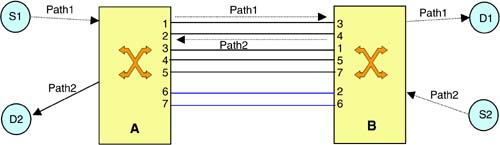
Switchover request: It seems like the Path message with the label request object could be used as an implicit switchover request (see section 7.5.3). The Path message, however, pertains to individual connections and not a link. Thus, if more than one connection is being routed over a failed link, a separate Path message must be generated for each such connection to switch it over to a protection link. But from section 8.2.1, we see that there is a need to designate one of the NEs engaging in span protection as the master. This is the node that should generate the Path message during protection. Path messages, however, flow from the node that was upstream to the node that was downstream during provisioning. If a failed link between two NEs A and B was carrying multiple connections, it is possible that for some connections A is the upstream node and for others B is the upstream node. This is shown in Figure 8-4. Here, the Path message for the connection provisioned from S1 to D1 flows from A to B. On the other hand, the Path message for the connection provisioned from S2 to D2 flows from B to A. In this case, it is difficult to uniquely designate one of the NEs as the master.
Figure 8-4. Path Message Flow
A solution to this problem could be use a different GMPLS RSVP-TE message for switchover request. For instance, it is possible to use the Notify message with additional information elements to indicate the IDs of protection links. Since the notify message can be sent both upstream or downstream, this would work. But then, this usage can hardly be considered as the use of the RSVP-TE protocol. Rather, the messaging would be an overlay over RSVP-TE.
Switchover response: The Resv message with the Label object (see section 7.5.3) can be used as an implicit switchover response. As in the case of the Path message, the Resv message pertains to individual connections. Thus, the same complexities outlined above arise with this usage. The solution is to use the Notify message with additional information elements. In this case, we are essentially using an overlaid protocol, as mentioned earlier.
In summary, it is definitely possible to use the control plane to realize span protection, but enhancements to the semantics of GMPLS signaling protocols would be required to do this. Path protection, however, falls more naturally within the framework of the GMPLS signaling protocols. This is described next.