As visual effects artists, we strive not only to re-create the natural world realistically, but also the camera's view of the world. These goals are by no means the same. The camera sees only a limited part of the world, and from a specific perspective.
Capturing a scene from this perspective requires a host of decisions that constitute a full-blown storytelling art known as cinematography. After Effects offers compositors the opportunity to re-create and even change some of these decisions, long after the crew has struck the set and called it a wrap. The title of the chapter may seem grandiose, given how many cinematographic choices are out of reach to compositors, but thinking like a director of photography and understanding the workings of the camera are the goals if you're going to fool the viewer into believing your effects shot.
This far-reaching chapter deals with several aspects of replicating a physical camera in After Effects and matching, influencing, or changing the camera's perspective, including
Taking control of the After Effects 3D Camera to replicate the settings of a physical real-world camera
Interpreting, managing, and re-creating other effects of using a film or video camera, including grain and lens distortion
Camera mapping a scene, making a 2D source three dimensional
Recreating both the look of camera blur and the effects of depth of field in the camera
Exploring different camera looks, including the fundamental distinctions between film and video, and how to recreate each
These seemingly disparate points all involve understanding how the camera sees the world and how film and video record what the camera sees. All of them transcend mere aesthetics, influencing how the viewer perceives the story itself.
What if you could pick up a camera and move it around a world of objects that were flat and two dimensional, yet were related to one another and to a virtual camera in 3D space? As was explored toward the end of the previous chapter, that's pretty much the dimensional model After Effects offers you. It's sort of a 2.5D world, comprised of objects that can exist anywhere but have no depth themselves.
There are a lot of fun, stylized ways to play around with 3D in After Effects, but there are also ways in which you can get the After Effects 3D camera to match the behavior of a real camera, if you understand how they are similar, and how they differ. Therefore it's worth taking a closer look at how 3D works in After Effects, and how its various features—the camera, lights, and shading options—correspond to their real world counterparts.
You can use 3D in After Effects without setting a camera—just toggle a layer to 3D and voila—but it's a little bit like driving a race track using a car with an automatic transmission: You can't maneuver properly, and before long you'll probably crash.
Furthermore, when you set a camera, you encounter one of the more helpful and visually descriptive portions of the After Effects user interface: the Camera Settings dialog (Figure 9.1). If you know how to interpret what it is showing you, the dialog's diagram tells you virtually everything you need to know about how the After Effects camera sees the 3D world.
Figure 9.1. Visual artists love visual user interfaces, and the Camera Settings dialog is one of the few to include a diagram. That's a good thing because it also contains a lot of settings that most users find a bit abstract. Here are the default settings for a 50 mm preset, which happens to be the setting that introduces no change of lens angle from a flat 2D view.
Virtually everything is an apt description, moreover, because one thing that is confusing about After Effects' camera is its use of lens settings from still SLR (single lens reflex) cameras to describe how long or wide a lens is. The diagram in Camera Settings, however, is helpful not only in making some sense of the numbers involved, but also in learning how cameras—be they real or virtual—operate.
The default camera in After Effects uses the 50 mm preset (listed in the Preset pull-down menu in the Camera Settings dialog). Switching all of your layers to 3D and setting this camera does not change the appearance of your scene whatsoever, which is significant. Like many added features in After Effects, it is specifically designed not to fundamentally change (or corrupt) the appearance of your work when you switch it on.
But hold on—there's no such thing as a 50 mm virtual camera lens because virtual space doesn't contain millimeters anymore than it contains kilograms, parsecs, or bunny rabbits. The virtual world is generally measured relative to pixels. Everything else is just kind of made up until you find its analogue in the real world. So where did the name come from?
On any physical camera, there is a lens length that would be considered neither long nor wide. This lens captures a scene without the shifts in perspective and distortion of features—not all of them displeasing, mind you—associated with lenses that tend more toward the fisheye or telephoto perspective (Figures 9.2 through 9.4).
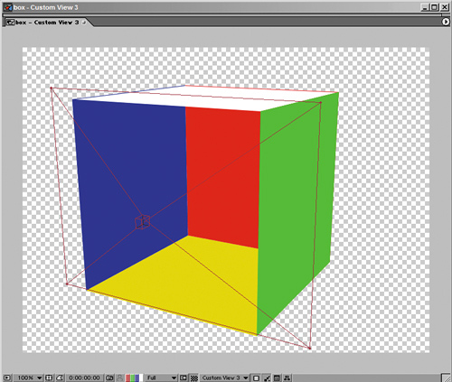
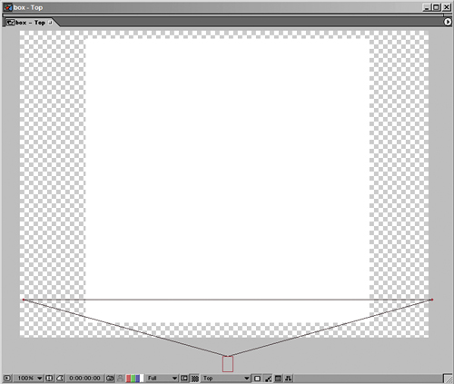
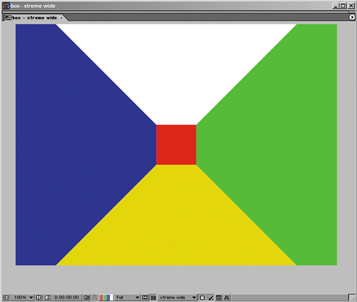
Figure 9.2. The extreme wide or fisheye lens pointed inside an evenly proportioned 3D box. Note that the “long” look of the box is created by this “wide” lens, which tends to create very strange proportions at this extreme. A physical lens with anything like this angle would include extremely distorted lens curvature.
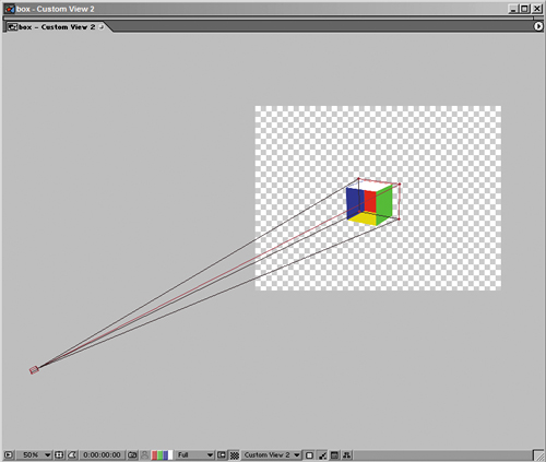
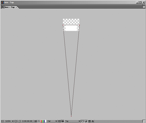
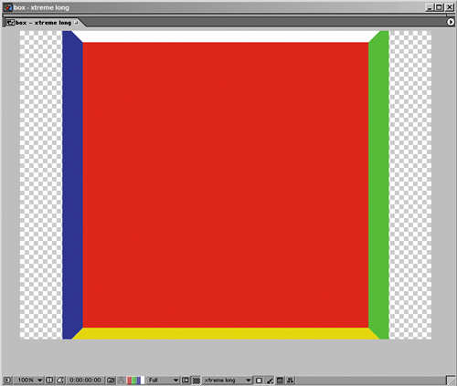
Figure 9.3. A telephoto lens (using the 200 mm setting) pushes items together in depth space, shortening the distance between the front and back of the box dramatically.
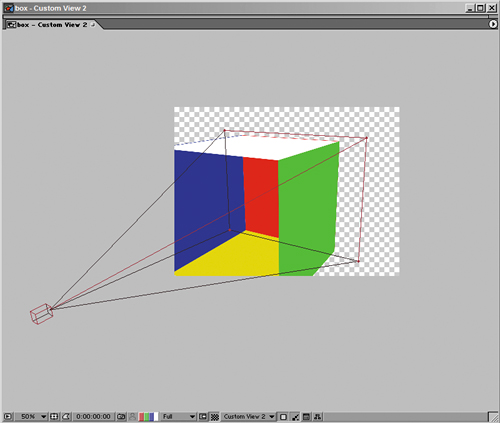
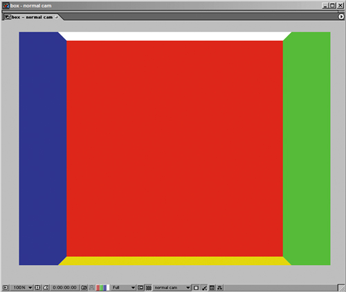
Figure 9.4. The default lens (50 mm setting). If the Z Position value is the exact inverse of the Zoom value, and all other settings are at the default, this is the view you get, and it matches the appearance of setting no After Effects camera whatsoever.
On a 35 mm SLR still camera such as has been used for professional photography for decades, 50 mm is the median lens length and the namesake for the After Effects preset. SLR cameras are familiar to many more people (including After Effects developers) than professional film or video cameras. But how many movies have been shot predominantly using an SLR camera? Not many; in fact, only one candidate comes immediately to mind, La Jetée, the 1962 Chris Marker film that was the inspiration for Terry Gilliam's movie 12 Monkeys.
Your source more likely would be from a 35 mm motion picture camera shooting Academy ratio, on which, it just so happens, a 35 mm lens is considered flat or normal. But if your footage would come from a miniDV camera, the tiny CCD requires an equally tiny default lens length of around 4 millimeters. The appearance of different lens lengths is directly related to the size of the backplate or video pickup, the area where the image is projected inside the camera. The smaller the film size (or CCD size), the shorter the default lens.
The point is that millimeters don't mean much without a physical lens and a physical camera. The only setting in the Camera Settings that truly, universally applies, whether images were shot in IMAX or HDV or created in a 3D animation package, is the Angle of View.
So how exactly do the After Effects camera's settings line up with those of a camera in the physical world? If you know a camera's settings, how do you use them?
First, look again at the diagram provided in the Camera Settings dialog. Four interrelated numerical fields—Film Size, Focal Length, Zoom, and Angle of View—are oriented around two triangles sharing a common hypotenuse (Figure 9.1). On a physical camera with a prime lens, these values would all be fixed. With a zoom lens, the Film Size would be fixed (as it always is in a physical camera), but the Zoom and Focal Length could be changed, resulting in a change in the Angle of View. These four settings, then, are interrelated, as the diagram implies.
Note
Yes, there is an optional, indirectly related, fifth numerical field in the Camera Settings diagram: Focus Distance, which you enable by checking the Enable Depth of Field toggle. This is more like a camera's aperture setting; I'll touch on it separately later.
And so it is with the After Effects camera: Change Angle of View, Zoom, or Focal Length and the other two values among those will change correspondingly, but Film Size will remain fixed. Film Size is useful only if you're trying to emulate a specific camera, which I'll get to in a moment.
Lengthen the lens, and Focal Length increases as Angle of View decreases. A physical telephoto lens really is longer from lens to back plate, and adjusting its zoom does make the lens longer or shorter. The only feature that would make this diagram any clearer is if it actually articulated to visually display the difference in Angle of View as clearly as it can be seen (particularly in the top views) in Figures 9.2 through 9.4.
The only two settings to focus on (no pun intended) are Zoom (for animation) and Angle of View (to match source where that measurement is available). Film Size and Focal Length, measured in pixels, make sense only relative to those two. Angle of View is the actual radius, in degrees, that the camera sees. The setting corresponds directly to real world cameras, and Angle of View is a setting you will see in other computer graphics programs, so you can match it precisely if you need to.
The Zoom value is the distance of the camera lens, in pixels, from the plane of focus of its subject. By default when you set a new camera, After Effects always sets that camera's Z Position value equivalent to the negative of its Zoom value, so that everything that is at the default Z position of 0.0 remains framed the same as it was before the camera was activated. The plane of focus represents an area the size of the composition (Figure 9.5), so wherever it is relative to the camera is the point where all items will be framed by that area exactly.
Figure 9.5. You can easily have overlooked the highlighted settings in the Camera Settings dialog. Comp Size (on the right) shows the horizontal size of the composition, in pixels, if the Units and Measure Film Size settings are as shown. This makes the relationship between Zoom and Plane of Focus clearer, although Comp Size is showing a horizontal measurement while the diagram makes it appear vertical.
There are several cases in which having the Zoom value in pixels is ideal. It helps for reference when creating depth of field effects, and it makes it easy to tie the position of the camera and the zoom together via expressions for depth of field and related effects (discussed later).
And how do you put all of this knowledge to work? You probably have one of two goals: Either you're matching settings that came from a real camera in order to match your elements to images taken with that camera, or you're creating a shot from scratch but want it to look like it was shot with a particular camera and lens. Here are some of the things you have to consider:
Depth of Field: Is everything in the shot in focus, or does the shot require a narrow depth of field with elements in the foreground and background drifting out of focus?
Zoom or push: If you are moving in or out on the shot, which type of camera move is it (discussed further in the section called “Moving the Camera”)?
Motion blur and shutter angle: These settings aren't part of the 3D camera, they're composition settings. If you're unclear about these, review Chapter 2, “The Timeline.” Note that camera movement can generate motion blur, just as layer movement does (Figures 9.6a and b). The key is that the objects to be blurred by the motion of the camera must have Motion Blur toggled on.
Lens angle and distortion: The perspective and parallax among objects in 3D space changes according to the angle of the lens through which they are seen. Real cameras also introduce lens distortion, a curving toward the edges of the image, especially apparent with wide angle lenses, which require a good deal of lens curvature (hence the fisheye lens) in order to take in such a wide angle of view. The After Effects 3D camera does not need a physical lens and does not cause lens distortion on images, but you may need to add it to match existing footage (see the “Optics Compensation” section).
Exposure: The After Effects camera has no direct corresponding adjustment for this feature (and limitation) of physical cameras. Therefore you needn't worry about it. But if, on the other hand, you want to create effects that emulate changes in exposure, you may be best off working with eLin (from Red Giant Software and on the book's CD-ROM) in a 16-bit linear image pipeline. For more on that, see Chapter 11, “Issues Specific to Film and HDR Images,” and for an example of working this way, look at the last section in Chapter 12, “Working with Light.”
One specific piece of information that can help you match existing footage is a camera report, a record of the settings used when the footage was taken. If the crew was large enough to include an assistant cameraman, this information was taken down and can be made available.
If you know the type of camera and the focal length used for your shots, you have enough information to match the lens of that camera with your After Effects camera.
Researched by Stu Maschwitz, author of Chapter 15, “Learning to See,” Table 9.1 details the sizes of some typical film formats. If your camera is on the list, and you know the focal length, use these to set your camera in the Camera Settings dialog. The steps are
Set Measure Film Size to Horizontally.
Set Units to Inches.
Enter the number from the Horizontal column of the chart that corresponds to your source film format.
Note

A potentially easier alternative to the listed steps, for those who like using expressions, is to use the following expression on the camera's Zoom property:
FocalLength = 35 //change to your  value, in mm
hFilmPlane = 24.892 //change to your  film size, in mm
this_comp.width*(Focal Length/hFilmPlane)
Set Units to Millimeters.
Enter the desired Focal Length.
Table 9.1. Typical Film Format Sizes
FORMAT | HORIZONTAL | VERTICAL |
|---|---|---|
Full Aperture Camera Aperture | 0.980 | 0.735 |
Scope Camera Aperture | 0.864 | 0.732 |
Scope Scan | 0.825 | 0.735 |
2:1 Scope Projector Aperture | 0.838 | 0.700 |
Academy Camera Aperture | 0.864 | 0.630 |
Academy Projector Aperture | 0.825 | 0.602 |
1.66 Projector Aperture | 0.825 | 0.497 |
1.85 Projector Aperture | 0.825 | 0.446 |
VistaVision Aperture | 0.991 | 1.485 |
VistaVision Scan | 0.980 | 1.470 |
16 mm Camera Aperture | 0.404 | 0.295 |
Super-16 Camera Aperture | 0.493 | 0.292 |
HD Full 1.78 | 0.378 | 0.212 (Full Aperture in HD 1.78) |
HD 90% 1.78 | 0.340 | 0.191 (90% Safe Area used in HD 1.78) |
HD Full 1.85 | 0.378 | 0.204 (Full Aperture in HD 1.85) |
HD 90% 1.85 | 0.340 | 0.184 (90% Safe Area used in HD 1.85) |
HD Full 2.39 | 0.3775 | 0.158 (Full Aperture in HD 2.39) |
HD 90% 2.39 | 0.340 | 0.142 (90% Safe Area used in HD 2.39) |
Your shot now has the correct Angle of View to match the footage, and so any objects that you track in (perhaps using the techniques described in Chapter 8, “Effective Motion Tracking”) will maintain the correct position in the scene as the shot progresses. It's vital to get this right if your camera is going to move during the shot, and especially if the lens used was at one extreme or the other, wide or long.
If a virtual camera is set with a wide lens angle, the software simply samples a wider (and taller) area of the scene, as you saw in Figure 9.2. This dramatically changes the perspective of 3D space, but it does not actually distort objects the way a real camera lens does because it relies on no lens whatsoever. All the software is doing is widening the view area and scanning, in a linear fashion, each pixel that falls in that area.
A real camera cannot simply widen its view area, which is essentially fixed. It can only “see” what is perpendicular to the surface of the lens glass, so it uses a more convex lens combined with a short lens length to pull a more disparate (wider) range of view.
At the extremes, this causes lens distortion that is easily visible; items in the scene known to contain straight lines don't appear straight at all, but bent in a curve (Figure 9.7). In a shot taken with a fisheye lens, it's as if the screen has been inflated like a balloon. It's rare, but not unprecedented, for a shot in a movie to look like this (but there are always exceptions, for example the point of view of a droid in a certain big-budget science fiction film).
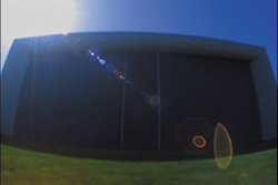
Figure 9.7. The somewhat psychedelic look of lens distortion at its most extreme. The lens aberration in this case is so extreme that even the flare caused by the front lens element is extremely aberrated. You could easily set an equivalently wide lens with the After Effects 3D camera, but none of the curving of what should be straight lines (the ground plane, the building outline) would occur.
As you work with more and more footage, particularly at film resolution (where the phenomenon is often more apparent), you start to notice that many shots that don't seem so extreme as a fisheye perspective have some degree of lens distortion. Even if you can't spot any curved edges that should appear straight at the edge of frame, you might notice that motion tracks from one side of the frame don't seem to apply equally well at the other side of the frame, proportions go out of whack, and things don't quite line up as they should (Figure 9.8).
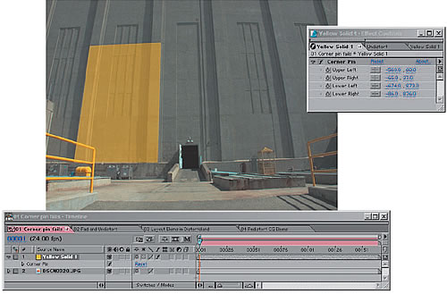
Figure 9.8. The curvature of items that you expect to be straight is one clear clue that there is lens distortion in this scene, but the surest sign is that an attempt to corner pin a yellow solid to the side of the building fails; it is not possible to make all four corners and edges line up properly.
There's no way to introduce lens distortion directly to a 3D camera, but the Optics Compensation effect (Professional version only) is designed to add or remove it in 2D. Figure 9.9 shows this effect in action. Increasing the Field of View makes the affected layer more fisheyed in appearance; to correct a shot coming in with lens distortion, check Reverse Lens Distortion and raise the Field of View (FOV) value.
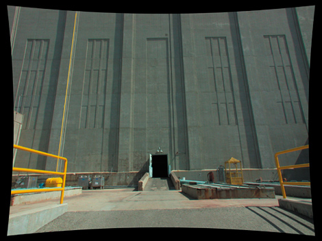
Figure 9.9. The process of removing distortion must take place in a composition larger than the source, padded to allow what happens to the corners of the image. The Beam effect is used on an adjustment layer, below the Optics Compensation effect, to act as a virtual “plumb line” to check the precision of a line near the edge of frame (where lens distortion is strongest).
This process is not exactly scientific, because the Field of View settings don't correspond to measurable phenomena, such as difference in Lens Angle. You have to look for what should be a straight line in the scene and adjust the setting until you're happy with the match. The specific workflow is
Having identified that there is lens distortion on a background plate to which you must add foreground elements (as in Figure 9.8), drop the background into a new composition that is at least 20% larger than the plate to accommodate stretching the corners.
Add an adjustment layer above the plate layer, and apply Optics Compensation to that layer. Check Reverse Lens Distortion and raise the Field of View (FOV) setting until lines that should appear straight in your image look straight.
Add a Beam effect below the Optics Compensation effect. Make its Inside Color and Outside Color settings match (using any color you'll be able to see easily), and align the Starting Point and Ending Point along an apparently straight line near the edge of frame. Fine-tune the Field of View setting a little more until the line is plumb (as in Figure 9.9).
Pre-compose all of these layers and set this new composition as a guide layer. In Figure 9.10, you can see that the corner pin is now successful, but you actually want to match the distortion of the source shot.
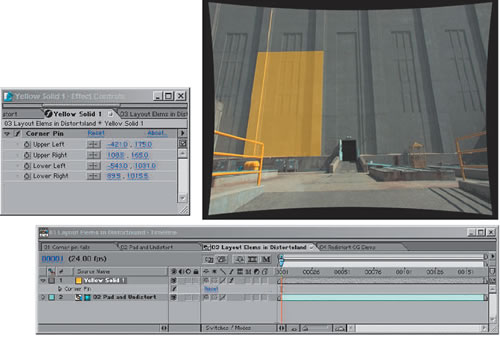
Figure 9.10. Over the undistorted background plate, you are able to freely position, animate, and composite elements as if everything were normal. Note that the perspective is still that of a very wide angle lens, but without the curvature. Any elements you positioned in 3D space would need to have a similarly wide Angle of View to match this perspective.
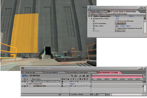
Create a new master composition containing the background plate and the laid-out foreground element. Copy Optics Compensation from the adjustment layer where you undistorted the background and paste it to the foreground element but turn off Reverse Lens Distortion. You have applied the exact distortion of your background to your foreground elements, and they now match up (Figure 9.11).
You have tricked After Effects into compositing elements into a distorted environment. Stu Maschwitz, who supplied me with the example used for the step-by-step figures, notes that it is important not to undistort and redistort the plate image itself, which will soften it dramatically. He summarizes the process with the following haiku:
undistort, derive
reunite distorted things
with an untouched plate
Using a 3D camera in an effects situation typically entails compositing 3D elements over a 2D plate background. This is no big deal. After Effects does not force you to decide up front whether your composition consists of a 2D or a 3D world, and it can contain both, layered together. This is a huge advantage as long as you're clear about managing the composition properly.
And why is it an advantage to mix layers in this manner? Once you understand it, you have a lot less to worry about:
A background stays in place no matter how you move the camera (as in the motion tracking examples using the 3D camera in the previous chapter).
2D adjustment layers set to comp size and default position affect the whole composition, including 3D layers, without budging.
Foreground from 3D programs that come in with 3D camera tracking data can be augmented in 3D while remaining rendered 2D elements.
Everybody wins.
Where are the gotchas of this approach? They are all special cases:
A 2D layer can use a 3D layer as a track matte and vice versa. Beware of using a 3D track matte on a 3D layer: It's rarely (if ever) what you want. One or the other layers typically needs to be locked in 2D space.
Some effects that emulate 3D perspective make use of the After Effects camera. Typically, and paradoxically, these work correctly on 2D layers only. Examples of this are Trapcode's Particular and 3D Stroke (Figure 9.12).
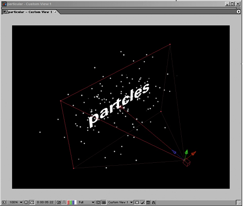
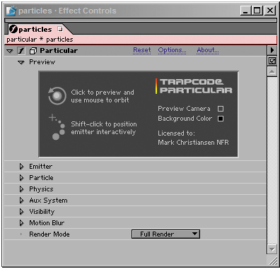
Figure 9.12. It seems incredible, but the particles generated by Particular, a Trapcode plug-in, are true 3D, as is evident in perspective view. Paradoxically, this 3D effect occurs when Particular is applied to a 2D layer. It calculates the 3D positions internally using the After Effects camera as a reference, an elegant workaround for the fact that 3D layers in After Effects are always flat planes.
Pre-composing a set of 3D layers effectively makes them behave like a single 2D layer. They no longer interact with other 3D layers or with the camera unless you enable Collapse Transformations for the pre-comp. Doing so bypasses the camera in the embedded composition, but respects the 3D position of the object. (For details, see Chapter 4, “Optimizing the Pipeline.”)
So go ahead, freely mix 2D and 3D layers. Just make sure, if it gets confusing, to double-check the gotchas list and ascertain that you know what you're doing.
A decision as simple as creeping the camera slowly forward can change the whole dramatic feel of your shot. The main limitation you face is the two-dimensionality of After Effects layers, but that's a huge step forward from the bad old days of optical compositing, when it was hardly possible to move the camera whatsoever.
Nowadays, most directors aren't satisfied with a locked-off camera for effects shots, yet it's often simpler to shoot an effects plate that way and leave the camera movement to the compositor. That's no big deal, as long as you don't completely break the rules for what you can get away with.
Keep in mind, moreover, where the audience is likely to be focusing their attention—every once in a while you get away with something you shouldn't. Robert Rodríguez made his entire directing career possible with this realization when he made El Mariachi, in which the many continuity errors failed to disrupt an action-packed story.
Specifically, I'm talking about not worrying about the effect of planes of motion and parallax for elements that are in the background, near the edges of the frame, appear for a few frames only, or otherwise won't be noticed by the viewer. The “Sky Replacement” section in Chapter 13, “Air, Water, Smoke, and Clouds,” contains just such an example, in which a flat card stands in for a fully dimensional skyline; people aren't watching the skyline for shifts in perspective, they're watching the lead character walk through the lobby and wondering what he's got in his briefcase (Figure 9.13).
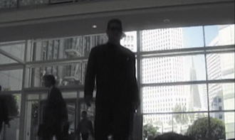
Figure 9.13. Prominent though it may appear in this still image, the audience is only subliminally aware of what is going on with that skyline outside the window. As the camera pans and tracks to the right, the pyramid building should creep out from behind the foreground skyscraper. It doesn't, because the background skyline is a tracked still, and no one notices because they're wondering what that silhouetted character in the foreground is going to do. (Image courtesy of The Orphanage.)
Note
You can toggle through the camera animation tools using the C key to orbit, track XY, and track Z in the active view. Remember, however, that you cannot orbit in isometric views (Top, Front, and so on).
You may feel you know all about working with a 3D camera already, but the After Effects version is slightly different from the 3D camera in other applications. For example, the After Effects camera has Transform options that are unique from all other types of layers (Figure 9.14), and a couple of things about them are a little strange to people used to other types of layers in After Effects, or other 3D programs. Take a closer look.
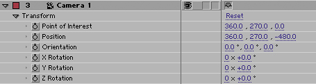
Figure 9.14. The Transform values for the camera include no anchor point and two sets of rotation data: the Orientation of the camera (its basic position), as well as separate X, Y, and Z rotation values. Separating these obviates the need for separate nulls to solve complex 3D rotations. The Point of Interest appears only with the default Orient Towards Point of Interest option (see Figure 9.15).
Note
The Y axis is upside down in After Effects 3D, just as it is in 2D. Long ago, before 3D in After Effects was even a glimmer in David Simons' eye, it was decided that the 0,0 point in After Effects space should be at the upper-left corner of the frame, so that increasing the Y value would move the layer downward on the Y axis. It was left this way when 3D was added for consistency's sake.
Certainly the biggest confusion about the After Effects camera stems from the fact that by default, it includes a point of interest, a point in 3D space at which the camera always points, for auto-orientation. To clarify
Auto-orientation via a point of interest is fully optional. You can turn it off (making the camera a free camera) or change it to orient automatically along the path of camera motion. To do so, context-click on the camera, then choose Transform > Auto-Orient or use Ctrl+Alt+O (Cmd+Option+O) to access the menu of settings (Figure 9.15).
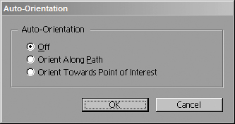
Figure 9.15. Many 3D camera tragedies could have been avoided if more After Effects users knew about this dialog box, (accessible via Ctrl+Alt+O or Cmd+Option+O). By turning off auto-orientation, you are free to move the camera anywhere without changing its direction. People who don't know about this end up trying to animate the camera's Position and Point of Interest values together—a nightmare.
If you need to move the camera and its point of interest, don't try to match keyframes for the two properties—this is sheer madness! You can parent the camera to a null and translate that instead.
Orientation works differently depending on whether auto-orientation is on (in which case it revolves around the point of interest) or not (in which case it rotates around its center).
The auto-oriented camera flips itself so that its view remains oriented, top and bottom, when crossing the X/Y plane while orbiting the center, but the free camera does not. This is great for positioning but not for animating—don't let it surprise you.
So although the default camera in After Effects includes a point of interest, it's often useful to do without it if you want to maintain or control the direction of the camera as you translate it through space. This may not come up in normal visual effects use very often, however, because the camera is often put to more modest uses, such as a simple-camera push.
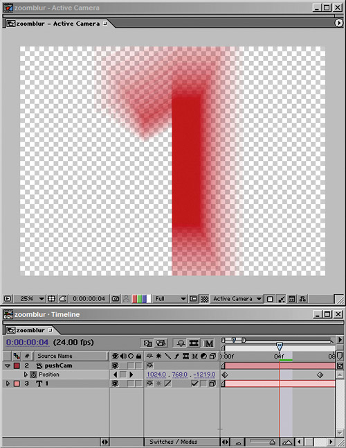
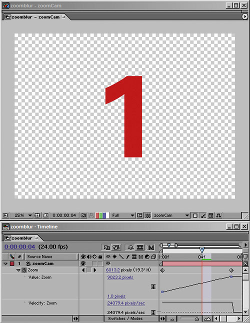
Knowledgeable effects artists understand that there is a huge difference between a camera push, in which the camera moves closer to the subject, and a zoom, in which the camera stays in place and the lens lengthens. You must make a conscious decision which type of move you're doing and adhere to the rules.
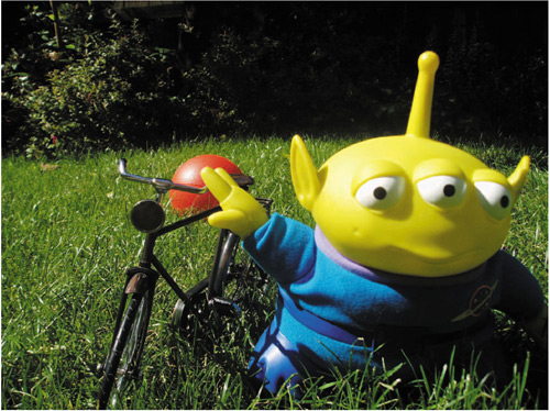
Figures 9.16a and b demonstrate the difference between pushing and zooming a real camera. Remember that zooming changes the actual lens angle, and has more of an effect on the immediate foreground and faraway background framing than a push.
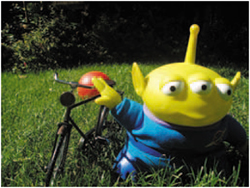
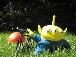
Figure 9.16a and b. The difference between a push in (9.16a) with a wide angle lens and a zoom (9.16b) from a distance is evident especially by what happens to the perspective of the orange ball in the background. With the zoom, its apparent scale is much greater, and it is much more prominent in shot. It seems to be closer to the foreground figures than in the image that was shot wider, but close-up.
Most of the time, you will animate a push; zooms, generally speaking, had their heyday in the era of Sergio Leone. That's a good thing because it is evidently easier to get away with a 2D push than a 2D zoom due to the static lens angle. The relationship and perspective of objects close up does not change with a push the way it does with a zoom.
Why use a 3D camera for a simple push when you could instead scale up the contents of a comp in 2D? If you're traveling any significant distance at all, a scale is too linear to achieve the illusion of moving in Z space. Instead, pick up a 3D camera and move that. You can add eases, stops and starts, a little bit of destabilization—whatever works for your shot.
When you perform your 3D push, however, do it on a single pre-composed layer rather than individual coplanar 3D layers, unless you're separating your source layers into planes of varying depth. Why? Because coplanar 3D layers easily lose proper layer order as After Effects calculates their movement in floating point space. There's no reason it should work, and you should avoid even attempting it.
Your camera move will look more natural if you add keyframe eases, giving the impression that there was a real camera operator behind the lens; if you're unclear about how to create an ease, check Chapter 2. You may even want to add a little extra hesitation or irregularity to the default ease curve to give it that feeling of a camera operator's personality (Figure 9.17).
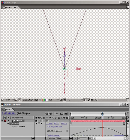
Figure 9.17. You can finesse a simple animation just by highlighting the keyframes and adding Easy Ease (F9 on your keyboard), but why stop there? Lengthening the Bezier handle for the first keyframe gives the camera that added realistic inertia moving from a static position.
But wait—a move in or out of a 2D shot—isn't that going to look wrong because it lacks any kind of parallax? It might, unless it's subtle. If you're dealing with enough of a move that planes of depth should change their relative perspective, 2D objects are probably not going to hold up. This goes doubly for tracking and panning shots, crane-ups, and other more elaborate and dimensional types of camera moves. Unless these moves are very small, you're going to blow the 2.5D gag. If in doubt, try it and ask neutral observers (or your effects supervisor) to tell you if they buy it.
The exceptions to the 2D object limitation are soft, organic shapes, such as clouds, fog, smoke, and the like. With these, you can fool the eye into seeing 3D depth where there is none, and you can get away with staggering them; the parallax even helps sell the shot. (For more on this, see Chapter 13.)
Camera projection (or camera mapping) is the process of taking a still photo, projecting it onto 3D objects that match the dimensions and placement of objects in the photo, and then moving the camera—typically only along the Z axis—providing the illusion that the photo is fully dimensional (right up until the camera move reveals some area of the image that wasn't part of the photograph). It has been used for some very elaborate visual effects sequences over the years and is often employed by matter painters as a way to keep 3D modeling simple and to focus efforts instead on painting.
Figures 9.18a, b, and c show a camera projection that Stu Maschwitz set up, ambitiously featuring the shapes of two parked military vehicles. Typical camera projection examples consist of such cube-shaped items as crates and boxes. In this case, a dozen separate planes were created to form a crude 3D model, all white and ready to receive a projected image (Figures 9.19a, b, and c). This example shows both the magic of this technique—deriving perspective shifts from a flat, still image—and the associated problems of image tearing when an area of the frame is revealed that had previously been obscured in the source photo.
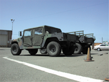
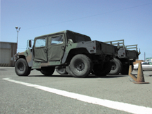

Figure 9.18a, b, and c. The progression from the source image (9.18a) through the camera move. By the final frame, image warping and tearing are evident, but the perspective of the image is essentially correct for the new camera position. The tearing occurs simply because as the camera moves it reveals areas of the image that don't exist in the source.
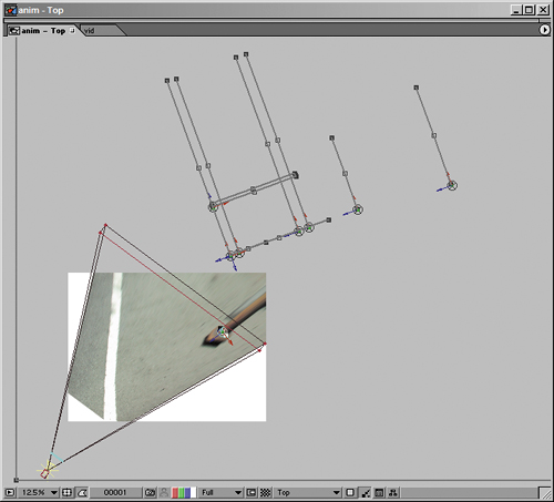
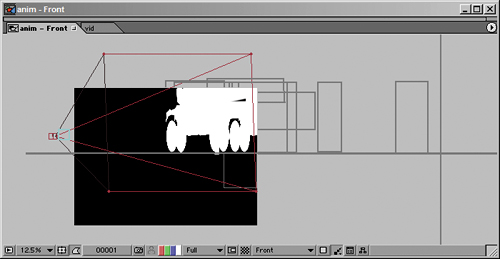
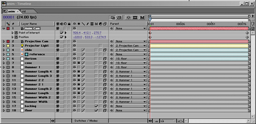
Figure 9.19a, b, and c. The rather complicated setup for this effect: from the top (9.19a) and side (9.19b) views you can see the planes that stand in for the vehicles and orange cone. Once setup is complete, animating the camera is a relatively simple matter (9.19c).
The key to pulling off an effect like this is obviously the setup: How is it that the one “texture” of the image (the photo) sticks to the 3D objects? The fundamental concept is actually relatively simple; getting it right is a question of managing details, and that part is fairly advanced and not for the faint of heart. The steps to projecting any still image into 3D space are as follows:
Start with an image whose most prominent objects can be modeled as a series of planes. This typically includes rectilinear objects, although in this example it also includes masking off such details as wheels.
Create a white solid for each plane in the image. Set each one to be a 3D layer, and under Material Options, change the Accepts Lights option to Off. This means that the planes will retain a pure white surface, ready to receive the projection of the image.
Add a camera called Projection Cam; if you know the Angle of View of your source image, set this camera to have that value. If not, you can experiment with zooming this camera in a moment, once setup is complete.
Add a light. Normally you would use a Spot light for projection maps, but After Effects lights have no fall-off so you're just as well creating a Point light. Give it the same position as Projection Cam, then parent it to Projection Cam. Change its Casts Shadows setting to On.
Rename the source image to reference, and duplicate it, naming the duplicate Slide. Turn on 3D for the duplicate, then under its Material Options, change Casts Shadows to Only and Light Transmission to 100%. This image now is cast by the light onto the white planes, as if it were a slide in a projector.
Parent Slide and Projector Light to Projection Cam. Now, no matter how you reposition the camera as you set up, those layers follow.
Next comes the potentially painful part: masking, scaling, and repositioning those white solids to build the model, ground plane, and horizon onto which you will project your slide. If it helps, toggle on the reference layer and build your model to match that, checking it with the slide every so often. Parent each set of planes to a null object so that you can easily change the position and scale of the whole object.
If planes that you know are at perpendicular 90 degree angles don't line up properly, you need to adjust the Zoom value of the Projection Cam, scaling the model and slide as needed to match the new Zoom value. The example file on the book's CD-ROM includes an expression applied to the Scale value of the slide layer so that the slide scales up or down to match however you adjust the Zoom of the camera. This isn't necessary but it's helpful in this example.
Once everything is lined up, duplicate Projection Cam, and rename the duplicate (the one on the higher layer) Anim Cam. This is the one you can now try animating, using the Point of Interest, Position, and Zoom from the Projection Cam as the default view at which everything looks just like the source photo.
The number of variables that may come up as you employ this technique with your own images are many, and the result is likely to exhibit the problems shown in the figures, so if this sounds like more trouble than it's worth, it probably is. If, on the other hand, you're feeling daring and ready to try something tricky, take a look at the example file, and feel free to give it a whirl.
Real cameras blur images in a particular way when areas of the image are out of focus. Plenty of camera operators in the history of filmmaking have regarded defocused areas of the frame as mistakes; Gregg Toland, visionary cinematographer of Citizen Kane, went to extraordinary lengths to keep items in the extreme foreground and background of that film in sharp focus, even devising (with Orson Welles) a customized camera for this purpose.
Nowadays, however, good-looking camera blur is not typically seen as a flaw. It has a practical purpose, putting the audience's attention where the director wants it, which is why a rack focus shot, in which the focus changes from a figure in the background to one in the foreground, or vice versa, is part of the cinematographer's palette of storytelling tools. It also is often considered beautiful to behold, so much so that the Japanese coined a term for the quality of the out-of-focus image, boke (also spelled bokeh, which is closer to a phonetic spelling).
So what's the big deal? Just blur the areas that should be out of focus, and you're done, right? Typically not, for a couple of reasons. First of all, as with lens flares, the design of the lens influences the look of the blurred image. Second, as is explored further in Chapter 11, if there are actual points of luminance in a blurred image. Be they lights or even specular highlights or glints reflected off of objects, they will retain their full brightness when blurred in a manner that images that simply have a blur applied to them do not.
Before I get to these special case scenarios and a discussion of what, exactly, boke means to your shots, take a look at a setup where the 3D camera in After Effects can help you re-create the type of blur caused by focal limitations in a physical camera.
If your source footage can easily be divided into planes of depth, you can achieve a rack focus effect that matches the way this effect is achieved in a physical camera. The focal point passes from an object in the foreground to one in the background or vice versa, and the depth of field is narrow enough that only the immediate plane of focus is seen in sharp detail.
With a physical camera, this type of shot requires a narrow depth of field, which is created by lowering the f-stop value. Doing so influences shutter angle and the amount of light passing through the aperture, so the color response and likelihood of motion blur in the shot are affected.
Not so with the After Effects 3D camera, which has Aperture and F-Stop settings as well (Figure 9.20), but they affect only focal depth. The two settings are tied together; changing one in the Camera Settings dialog has an inverse effect on the other and the mathematical relationships are not linear. F-Stop is the setting more commonly referenced by camera operators, and yet only Aperture is available to be adjusted and keyframed in the timeline.
Figure 9.20. By checking Enable Depth of Field in the Camera Settings dialog, you enable the settings associated with it, including Focus Distance (the distance in pixels that is in focus, which can be locked to the Zoom value using the check box just below it), as well as Aperture and F-Stop, which are different methods of controlling the same thing: the relative depth of field. A low F-Stop (or high Aperture) as shown here with a Blur Level of 100% will create a shallow depth of field.
After Effects depth of field settings can be matched to a camera report, provided that you have the camera f-stop setting that was used when the footage was shot. If so, open up the Camera Settings dialog (Ctrl+Shift+Y/Cmd+Shift+Y, or click on the Camera in the Timeline window), check the box labeled Enable Depth of Field, and enter your value for F-Stop.
The key to this effect is to offset at least one layer in Z space so that it is out of focal range. Now you can animate Focus Distance in the timeline; in the Top view, set the Focus Distance (under Options) to match the layer that will be in focus at the beginning of the shot, and keyframe it, then change the Focus Distance to match a second layer later in the shot (Figures 9.21a and b).
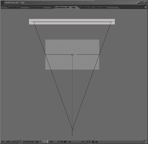
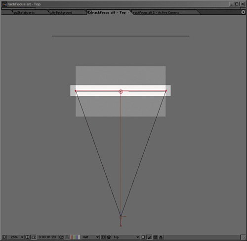
Figure 9.21a and b. In the Top view it is easy to animate the Focus Distance, denoted by a red boundary line, to animate from the far plane (9.21a) to the near plane (9.21b).
A static focus pull doesn't look quite right; changing focus on a real camera always alters the zoom slightly. To sell this shot, which starts on a view of the city and racks focus to reveal a sign in the foreground, I add a slight camera pull-back, which takes advantage of the nice shift in planes of motion that I get from my repositioned layers (Figure 9.22).


The rack focus method generates camera blur that is realistic as far as moving and changing focus on a camera go, but the After Effects camera is not capable of generating the look of a truly defocused lens because of what happens to out-of-focus points of light that pass through a camera lens and aperture.
Boke is meant to connote the look and feel of how points of light become discs of light (also called circles of confusion) that take on the character of the lens itself, as with lens flares (another effect that is the result of the lens interacting with light, covered in Chapter 12). This would seem to be rather obscure and arcane, except it produces beauty and suspense in a movie.
How so? Shots create suspense by keeping elements out of focus. We may have a notion of what we are seeing, or we may not (Figure 9.23). We remain intrigued as viewers as the shot focuses in from a strange wash of color and light (Figure 9.24).

Figure 9.23. Offered a dollar by Stu if I could guess what this image is, I guessed a beanbag chair. I was wrong. The correct answer is at the end of this section.


Figure 9.24. Even in the very first, most blurred frame of this shot pulling back from the lawn, you have a good idea what you're looking at, yet the appearance is strange and compelling. Note that a few blades of grass in the extreme foreground retain the quality of boke although most of the shot is in focus.
So what, exactly, causes this phenomenon, and how should you think about it? A perfect lens, photographing a point of light that is out of focus, creates a soft, spherical blur to represent that point. What was a bright point is now an equally bright, larger, softer area. If you tried to re-create this effect by simply blurring an image, the blur would have the effect of graying out toward the edges rather than retaining the brightness of the source. This is true not only of blurs that result from defocusing, but of motion blur as well (Figures 9.25a, b, and c).

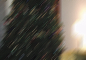
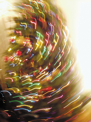
Figure 9.25a, b, and c. Motion blur generated the standard way (9.25a and b) literally pales in comparison to true motion blur on illuminated elements (9.25c).
Moreover, most camera lenses are not perfect, so you will not see perfect blurred spheres. The digital images in Figure 9.24 show spheres that are brighter toward the edges than in the middle; an anamorphic lens will show squashed spheres, and as with lens flares, the blades of the aperture diaphragm will sometimes be visible in the circles of confusion, making them hexagonal (or pentagonal, and so on, depending on the number of blades in the opening).
Okay, let's say you're sold on the look of boke blur and want to incorporate its effect into your shots. What can you do in After Effects to recreate it?
In Chapters 11 and 12, guest author Brendan Bolles and I look at ways in which working in true linear color space can help recreate at least one aspect of realistic camera blur—that the hotspots do not dim down as they are blurred, but retain their brightness. True linear color includes overhead for overbright pixels, and so you can build up a boke-like effect by building up (via Add mode) and blurring elements in the scene that should appear brighter than the surrounding scene. The re-lighting tutorial at the end of Chapter 12 includes creation of a sun sphere in just this manner.
There are also third-party solutions out there to help you fake this effect. I don't mean the verb “fake” to connote that you should instead go for the “real” method. This phenomenon occurs only when a blurred or defocused element passes through a physical lens, so if you're recreating this in After Effects, faking it is your only option. The best tool on the market for creating good-looking lens blurs is probably Frischluft's Lenscare (for After Effects and Photoshop). The default settings are not reliable, but if you're willing to make some adjustments and use such optional additions as depth maps (for 3D footage), you can derive some lovely results with this plug-in (www.frischluft.com).
You might not be able to recreate the look of that twenty-dollar bill in Figure 9.23 so easily, but if you pay attention to what happens in these surprising reference images, your camera blur will be that much closer to what you would get out of a real, defocused camera.
Note
If you're interested in learning more about the phenomenon of boke, good information is available on the Web. At www.bokeh.com you will find links to essays and tests exploring camera blur, including an excellent essay from luminouslandscape.com written by Michael Reichmann.
Beyond lens effects, you will need to consider another attribute of images shot with a real camera: grain. Grain is essentially high-frequency noise that occupies every channel of your shot to some degree. And grain is your friend, as long as you give it the proper amount of attention.
Grain can give texture and life to images and help to conceal a multitude of small details, enabling compositors to get away with illusions. Just like depth of field and motion blur, grain can be a problem or the key to a whole cinematic look.
Note
The day may come when digital cameras are capable of delivering moving footage that has no grain whatsoever. Already, high-definition video cameras used to shoot movies pick up clearer detail than film cameras, all other things being equal. For example, miniatures for Star Wars, Episode One: The Phantom Menace, the first big-budget film to be shot on digital video, had to be created with greater detail than typical film miniatures because of what the digital camera exposed.
For compositors, perhaps the most important role of grain is its role integrating a flat, static layer with moving footage, adding life to an element that otherwise looks oddly suspended out of the time and place of the rest of the scene (Figure 9.26).
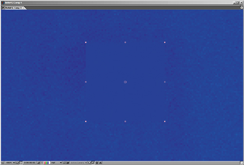
Figure 9.26. Solid areas of color are always the best for examining grain, and it always appears, even on perfectly shot 2 K film plates (here zoomed in to 400%). Drop in a solid the same color as the plate, and you see that it fails to blend with its surroundings. The effect is even more pronounced with moving footage, especially at film resolution.
Proper grain is not simply switched on or off, however; it needs to be carefully adjusted. You can become quite theoretical about all this, but really you need to concern yourself with only two basic factors:
Size of the grain
Amount of grain, or amount of contrast in the grain
The trick is that these factors typically vary from channel to channel. Blue is almost universally the channel likeliest to have the most noise; happily the human eye is less sensitive to blue than red or green, but this can be bad news for blue-screen shoots.
How much grain is enough? As with color in Chapter 5, “Color and Light: Adjusting and Matching,” your goal is typically to match what's there already. If your shot has a background plate with the proper amount of grain in it, you match your foreground elements to that. In the case of a fully computer-generated scene, you might have to match surrounding shots that have plate reference, which you would match in the same manner.
Note
Grain is often the result of a low amount of light coming through the lens combined with a low-quality image-gathering medium, such as 8 mm film or miniDV, that has poor light-gathering abilities or large silver particles (typical of faster, cheaper film stocks).
After Effects 6.5 Professional includes a suite of three tools for automated grain sampling, grain reduction, and grain generation: Add Grain, Match Grain, and Remove Grain. Add Grain you adjust entirely manually, but Match Grain and Remove Grain sample a noise source layer to give you an initial result that you can then adjust.
If you've been reading closely up to this point, you know I'm not a fan of using the automated solutions. Not so in this case. The Match Grain effect does not seem to be appreciably slower due to grain sampling than Add Grain, which does not perform any sampling and includes all of the same controls. Therefore, I recommend you see what Match Grain can come up with as a starting point, and then work from there. In either case, the steps are the same:
Look for a section of your source footage that contains a solid color area and little or no motion for 10 to 20 frames. Most clips have this, and those that don't tend to let you be a bit more fast and loose with grain anyhow.
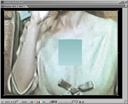
Zoom to 200% to 400% on the solid color area, and create a Region of Interest around it. Set the Work Area to the 10 or 20 frames with little or no motion.
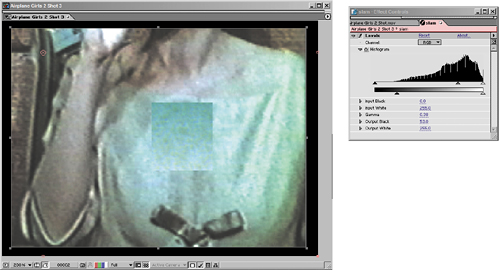
Add a solid that is small enough to occupy part of the Region of Interest. Apply a Ramp effect to the solid, and use the eyedropper tools to select the darkest and lightest pixels in the solid color area of the clip. The lack of grain detail in the foreground gradient should be clearly apparent (Figure 9.27).
Apply the Match Grain effect to the foreground solid. Choose the source footage layer in the Noise Source Layer pull-down. As soon as the effect finishes rendering a sample frame, you have a basis from which to begin fine-tuning. You can RAM preview at this point to see how close a match you have. In most cases, you won't be done yet.
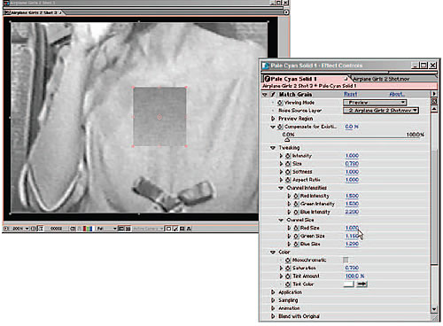
Twirl down the Tweaking controls for Match Grain, and then twirl down Channel Intensities and Channel Size. You can save yourself a lot of time by doing most of your work here, channel by channel.
Activate the red channel only in the Composition window (Alt+1/Option+1) and adjust the Red Intensity and Red Size values to match the foreground and background (Figure 9.28). Repeat this process for the green and blue channels (Alt+2/Option+2 and Alt+3/Option+3). RAM preview the result.
Feel free to adjust the overall Intensity, Size, or Softness controls under Tweaking according to what you see in the RAM preview. You may also find it necessary to reduce Saturation under Color, particularly if your source is film rather than video.
In most cases, this is all you need to do for a result that will work. You can copy the effect and paste it to any foreground layers that need grain. If the foreground layer already contains noise or grain, you may need to adjust the Compensate for Existing Noise percentage for that layer.
Obviously, I left a lot of other controls alone (Figure 9.29); the Application category, for example, contains controls for how the grain is blended and how it affects shadows, midtones, and highlights individually. Typically these are overkill, as are the Sampling and Animation controls, but how far you go in matching grain before your eye is satisfied is, of course, up to you. This is one more case in which slamming the result can help ascertain its effectiveness (Figure 9.30).
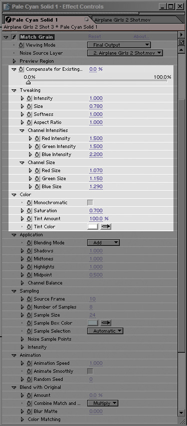
Figure 9.29. Match Grain clearly has a lot of controls, and yet the ones you will use most often are in the highlighted region, mostly under the Tweaking and Color categories. It is best to go top to bottom, first adjusting overall Intensity, Size, and Softness, then refining the individual Channel Intensities and Channel Size (as in Figure 9.28).
Using Noise for Grain
Prior to the addition of Add Grain and Match Grain to version 6.5 Professional, the typical way to generate grain was to use the Noise effect. The main advantage of Noise effect over Match Grain is that it renders 20 times faster. The downsides are that After Effects doesn't make it easy for you to separate noise channel by channel, nor can you hold out noise to foreground elements only while viewing the background. Scaling it requires a separate effect. But adding grain is one of those areas where you can often get away with less than 100% accuracy.
You can use three solid layers, with three effects applied to each layer: Shift Channels, Noise, and Transform. You use Shift Channels to set each solid to red, green, or blue, respectively, set their Blending Modes to Add, and set their Opacity very low. Next, set the amount of noise and scale it in the Transform effect.
If the grain is meant to affect a set of foreground layers only, hold them out from the background plate either using pre-composing or track mattes. If this sounds complicated, it is, which is why Match Grain is the better choice if it's available.
Removing grain, or sharpening an image in general, is a completely different process from adding grain. Typically on a production that has been well shot, however, you'll rarely have a reason to reach for the Remove Grain tool.
If you do, your reason will probably be unique to your particular footage. In such cases, you may very well find that Remove Grain at the default settings gives you a satisfactory result. If not, check into the Fine Tuning and Unsharp Mask settings to adjust it.
Remove Grain is often most useful sort of “behind the scenes,” in other words not across the whole final shot (Figure 9.31), or in combination with other effects. If you're using Remove Grain to improve the likelihood of a clean blue-screen or green-screen key, apply the resulting matte back to your source footage as an alpha track matte. That way you get the best of both worlds: a clean matte channel and realistic grain on the source color layer.
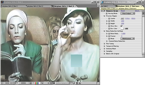
Figure 9.31. Although it may look nice for a still figure in a book, the results of Remove Grain applied to the whole shot at the default settings are rarely what you want. The solid with the Ramp effect now matches quite well with no grain applied to it whatsoever, but in full motion the grain-reduced shot looks a bit strange and retains a certain soft lumpiness. Still, it's a powerful tool if you need it, and you can certainly dial it back.
Note
Chapter 10, “Expressions,” offers a unique and highly effective strategy for removing extreme amounts of grain from a locked-off shot using expressions.
The most obvious time to add grain to a layer is in cases where the layer is computer-generated or a still image. In either case, it will lack any of the moving grain that you would find in film or video footage. Pixar does not add grain to its final shots because they are internally consistent; none of the shots originated on film or video, so they all lack appreciable grain. As soon as your shot has to match anything that came from a camera, and particularly if it's going to be projected, you need to manage grain.
You also may have to add grain to an element if it has blur applied to it. Blurry source shots can still contain quite a bit of grain over the blur because the grain is an artifact of the medium recording the image, not the subject itself. Elements that are scaled down in After Effects also have the grain scaled down, another case in which it may be necessary to restore it.
Blue-screen footage that has been keyed may also need grain added. Remember, the blue channel contains more grain, typically, than red or green. Suppressing the blue channel in a color key operation, therefore, can also suppress grain too much for it to match other footage.
Other compositing operations can enhance the grain of an element. Sharpening, if it is not done via the Remove Grain tool, can strongly emphasize grain contrast in an element, typically in a not-so-desirable manner. Sharpening also brings out any nasty compression artifacts that come with footage that uses JPEG-type compression, such as miniDV video.
Lack of grain, however, is one of the big dead giveaways of a poorly composited shot. It is worth the effort to match the correct amount of grain into your shot even if the result isn't apparent as you preview it on your monitor. Especially when outputting to film, but even with video, elements with the wrong amount of grain stand out unpleasantly and fail to look natural.
Grain is only one of the many properties associated with a film look. People tend to mean different things when they speak about a film or video look. That's because they have different purposes in mind for creating these looks.
I can think of two very different reasons to shoot video and try to make it look like film:
The story calls for a sequence to appear as if it was shot on old home movie stock, such as Super 8 (a popular format from the '60s and '70s).
The filmmaker wants to shoot as cheaply as possible, yet achieve the look of an expensive feature film.
The first situation is relatively simple and straightforward. In the same way that you match the color and grain of foreground elements to the background, you can match a whole shot to the look of an old film stock using those same grain and color tools, plus maybe extra tricks, such as a vignette effect, which offers the look of projected film, brighter in the center and fading to black at the edges (Figure 9.32). As always, I encourage you to get reference if you're not sure what to do.
Figure 9.32. The easy clichés of film: heavy grain, a light vignette effect, a slight leaning away from saturated reds and yellows. These are stylized ways of telling the audience it is looking at a filmic image.
The second situation, however, is nearly broad enough to constitute a whole other book. I almost hesitate to bring it up in the context of a visual effects book, but I've seen enough situations in which a student or low-budget filmmaker clearly went for a filmic look and missed in elementary ways that it seems helpful to offer a few pointers. If, for example, you are just starting out and creating a shot to go on a reel to apply for jobs in the film industry, your work will be judged more harshly if it seems to have gone for a film look and failed.
Note
This discussion, by the way, is nothing against the look of video. There could, hypothetically, be a situation in which you wanted something shot on film to look as though it were video. That's unlikely given basic economics, however; film is far more expensive than video, and although we may see its virtual demise in our lifetimes, it retains a cachet that video lacks. On the other hand, if you submitted a reel to any of the top of visual effects facilities in the world and you had convincingly made it look like your visual effects shot was taken with a Handycam, there is no doubt you would get the job.
Here are three important distinctions that come into play differentiating film from video that I have seen novices overlook:
Garbage in, garbage out. It sounds obvious, but if you're shooting your own footage (say, on miniDV tape), simple decisions that you make when you shoot can have profound consequences when it comes time to make the shot look its best. Too often, artists learn too late what they end up trying (and failing) to fight against in postproduction.
Frame rate and format matter. Frame rate and format might seem to be inconsequential or a matter of personal preference, but I would argue that when low-budget video producers are trying to make shots look filmic, frame rate, at least, might be the most important ingredient.
Color affects story. Changes to color and contrast can change the overall mood of a shot.
The following sections offer a few simple pointers for anyone with an effects shoot on a tight budget and the goal of producing a shot that will stand up against feature film footage.
Garbage in, garbage out isn't a new principle. But what does it mean in this context? Here are some specifics (with details following):
Don't try to do things on set that you can easily add in post, but equally, don't neglect things on set that will be difficult if not impossible to fix in post.
Don't underlight a scene, but for God's sake don't overlight it. Keep the contrast low.
Plan carefully: Storyboard, scout, and eliminate variables.
The most radical thing you can do on set to ensure a good result when shooting miniDV or HDV video is to aim for a low-contrast master that looks horrible to the director of photography. As Stu Maschwitz said about shooting this way, “The on-set monitor [is] not the answer print but the negative.” Whites in particular, once blown out, are impossible to recover (Figure 9.33).
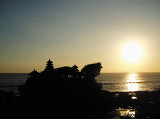
Figure 9.33. Sunsets are notoriously difficult for digital cameras to capture. Once those hot areas of the image are blown out, they're not coming back, nor is detail returning to the foreground. Even in lower-contrast images, as the color levels approach full white or black, you lose all room to maneuver in After Effects. This problem is a centerpiece of Chapter 11.
Most camera operators would be inclined to deliver an image on set that looked as close as possible to how the final should look. This is often an appropriate strategy with film. With digital video, however, shooting a low-contrast source leaves ample room to bring out a high dynamic range using tools such as Levels and Curves in After Effects.
Many artists would argue this point, but I'm going to go out on a limb and say it straight out: If you want your footage to look filmic, the frame rate had better be 24 fps.
One of my favorite demonstrations of the difference between 24 fps film and 60 field per second NTSC video dates back to the Golden Age of television and is available on DVD. In 1960, when the original Twilight Zone was in production, the crew decided to shoot on video rather than film during the second season as a cost-cutting measure.
The experiment lasted six episodes (“Static,” “Night of the Meek,” “The Lateness of the Hour,” “The Whole Truth,” “Twenty-Two,” and “Long Distance Call”), then was abandoned. The difference in how the drama “reads” on video versus film is simply incredible. The video versions are almost like watching a soap opera; the film versions retain all of the spare, noir ironic distance and mystique that made the series famous. In short, the videotaped versions have immediacy, but the film versions seem timeless.
If you're with me on this, but you're still faced with shooting NTSC video, consider carefully if there's any way to capture your footage using the slower frame rate. It is certainly possible to convert 29.97 fps video to 23.976 fps (other-wise known as 24 fps), but the resulting motion will stutter as every fifth frame is skipped. Many contemporary video cameras include a 24 fps mode; prior to that, digital filmmakers would use 25 fps PAL format cameras and slow the footage down to 24 fps. These options are worth considering.
Again, if the immediacy of the reality television look is what you're after, by all means, go for it: Shoot your source with a consumer video camera and match elements to that. It's not a question of better or worse, it's a question of immediate versus timeless.
Note
The numbers “1.85” and “2.35” referred to the ratio of the width to a height of 1, so it's the same as saying 1.85:1 or 2.35:1, respectively. The 16:9 format, which has become popular with digital video, is equivalent to a 1.77:1 ratio, slightly narrower than Academy, but wide compared to the standard television format of 4:3 (which translates to 1.33: 1). See Chapter 11 for more on this.
As the world transitions from standard definition to high-definition broadcast television, formats are making the same transition that they made in film half a century ago. The nearly square 4:3 aspect ratio is giving way to wider formats: 16:9, 1.85 Academy aperture, even 2.35 Cinemascope, and who knows what next.
Big-budget films are often made for more than one format, and you can do the same with some preplanning. When the film is intended both for theatrical release and the home video market, all of the effects might be created at a 4:3 aspect ratio and then masked off for the wider theatrical version. This is fine as long as you're aware at every stage of production what the safe areas of your frame are. For example, on The Day After Tomorrow the theatrical mask sat near the top of the frame, so that all of the less-essential action had to be planned for the bottom of the frame. This one had the nickname Ueli-mask, after the film's cinematographer, Ueli Steiger.
The influence of color decisions on the final shot, and by extension on the story being told in the shot, is a big topic, discussed by cinematographers and colorists the world over. Trying to distill it into a few pithy paragraphs here would do it a disservice.
So here's a suggestion: If you're new to the idea of developing a color look for a film or sequence, get reference. Study other people's work for the effect of color on the mood and story in a shot, sequence, or entire film. Figure 9.34 is taken from an independent short film series shot on DV but intended to parody the look and attitude of big budget action movies; the transformation of before and after is fairly radical.
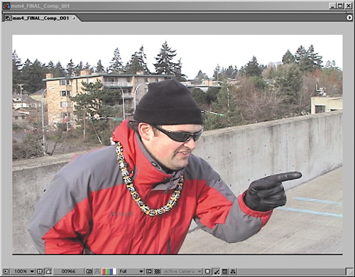
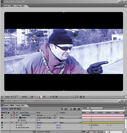
Figure 9.34. Radical color transformation is undertaken to give this no-budget action movie parody the feel of one of the films it satirizes. Techniques such as using a color solid to transform the lighting and color of footage are explored throughout Chapter 12. (Images courtesy of markandmatty.com.)
You can find third-party plug-ins dedicated specifically to lending a film look to video. Many are dedicated to the first motivation for creating a film look: They can make your shot look grainier, scratched, vignetted, jittery, and generally like it was shot with the oldest, most poorly maintained film camera in the world, with the negative being dragged across the floor of the lab and stepped on for good measure.
Reliable methods for fabricating the expensive film looks of twenty-first century Hollywood, however, are harder to come by. Stu Maschwitz developed the Magic Bullet Suite (a set of plug-ins for After Effects and Apple's Final Cut Pro) so that The Orphanage could help filmmakers who want to shoot on cheap and easy miniDV cameras, but who demand the look of film; thereafter, the software was made publicly available. Amongst the suite's many tools are Magic Bullet, which converts video footage to 24 fps with special emphasis on de-artifacting, and Look Suite, which contains preset looks designed to match existing film styles and processes. There is no direct replacement for these tools (which you can check out for yourself on the book's CD-ROM), but Chapter 12 looks at simpler ways to match certain looks.
And really, you've just scratched the surface of what's possible. The inventive compositor can and should always look for new methods to replicate the way that the camera sees the world, going beyond realism to present the realism we've become so accustomed to seeing—realism through the lens.