Chapter 12. Networks
Never let the future disturb you. You will meet it, if you have to, with the same weapons of reason that today arm you against the present.
—Marcus Aurelius Antoninus, Meditations
No town or freeman shall be compelled to build bridges ... except those with an ancient obligation to do so.
— —The Magna Carta
In this chapter, we’ll look at connecting your embedded computer to the real world by adding a Local Area Network (LAN) interface. There is a wide variety of networks employed—some very common, some not so common. We’ll take a look at CAN and Ethernet, the two most common networks. CAN is a network for industrial applications, where a conventional network just won’t do. CAN is suited to electrically noisy and harsh conditions and is the network of choice in electrically severe environments. Ethernet is the intranet network that connects the world’s desktop computers, as well as a host of other devices such as routers, gateways, printers, and other peripherals.
Controller Area Network (CAN)
Through the late 70s and 80s, the complexity of automotive electronics grew considerably, with engine-management systems, ABS braking, active suspension, electronic transmissions, automated lighting, air-conditioning, security, and central locking. Each of these systems does not exist in isolation but is part of an integrated whole. A considerable amount of information exchange is required, and, therefore, some means of system interconnection must be provided. The conventional method was point-to-point wiring, which provided discrete interconnection between each subsystem. This methodology was a natural evolution from the simple electrics of earlier cars, but as automotive complexity grew, such a scheme proved vastly inadequate. Each car could have several kilometers worth of wiring and dozens of connectors. Such complex wiring systems added greatly to the cost of producing a car, added unnecessary weight, reduced reliability, and made servicing a nightmare.
The obvious solution was to replace complexity with simplicity and implement intersystem communication using a low-cost digital network. The automotive electrical environment is very noisy. With electric motors, ignition systems, RF emissions, and so on, the 12 V supply to automotive electronics can have ± 400 V transients. The required communication network must therefore be able to cope with this noise and work reliably. The network must provide high-noise immunity and error detection and handling, with retransmission of failed packets. Thus was born the Controller Area Network, more commonly known as CAN, implementing real-time communication at up to 1 Mbps, over a 2-wire serial network. CAN specifies only the physical and data-link layers of the ISO-OSI model, with higher layers left to the specific implementation.
Bosch developed CAN in Europe in the late 1980s, originally for use in cars. Because of its robustness, CAN has expanded beyond its automotive origins and can now be found in industrial automation, trains, ship navigation and control systems, medical systems, photocopiers, agricultural machinery, household appliances, office automation, and elevators. CAN is now an international standard under ISO11898 and ISO11519-2.
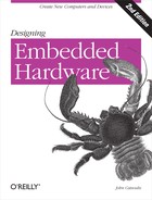
CAN supports multiple masters on the network, with each master responsible for local sensing and control within the distributed system (Figure 12-1).
Each CAN packet contains address information and priority as part of the header, and the nodes may connect to the network, or disconnect from the network, without affecting network traffic between other nodes.
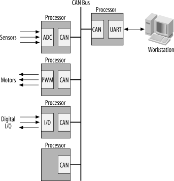
The CAN network uses wired-AND logic, with a maximum bus length of 1,000 meters (3,300 feet), and a bus length of 40 meters (133 feet) at maximum data rate over twisted-pair wiring. Each end of the bus requires termination resistors to prevent transmission reflections (Figure 12-2).
Many processors intended for use in harsh or electrically noisy industrial applications include a CAN module. A number of Philips microcontrollers include CAN, as do a few PICs. The DSP56805 processor covered in Chapter 19 also has a CAN interface. For processors that do not include CAN, CAN interface modules are available. The Microchip MCP2510 provides a CAN module and interfaces to a host processor via SPI. Adding CAN to any embedded system is therefore a simple task.
Typically, a microprocessor that supports CAN will include a CAN interface module, which provides most of the functionality. The only additional support required is a CAN interface driver. Philips Semiconductor produces a CAN driver, the PCA82C250T, which makes interfacing to the CAN bus very easy.
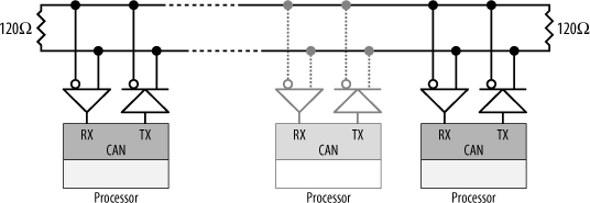
Your embedded computer must also have some way of physically attaching to the bus. The simplest method is simply to bring the bus into the computer system on one connector, tap off it, and then route it out through another connector (Figure 12-3).
To see how we can use CAN, let’s look at the DSP56805 processor. This processor has a CAN network module as part of its suite of onboard peripherals. The schematic for interfacing a processor’s CAN module to a CAN bus is shown in Figure 12-4.

The DSP56805 has two CAN interface signals, MSCAN-TX and MSCAN-RX, which are the CAN transmitter and receiver, respectively. These are connected to the PCA82C250T, which provides the interface to the CAN bus. Note that the DSP56805 requires a 3.3 V supply, while the PCA82C250T requires a 5 V supply. A pull-up resistor brings the MSCAN-TX output of the processor to the required logic-high level for the PCA82C250T. While CAN requires only two signal lines and ground, the actual connectors have eight pins. Since the CAN bus requires a termination resistor at each end, we provide a 120 Ω resistor should our computer be placed at the bus end. A jumper allows it to be brought in-circuit or disabled as needed. So, if our computer is at the end of the CAN bus, the jumper is closed and the bus is terminated. If our computer is not an endpoint machine, the jumper is left open and the resistor plays no part. Note that having a termination resistor active (jumper closed) when this computer is not at an endpoint is a good way to ensure an unreliable CAN bus! Resistors should be active at bus ends only.
Many implementations of CAN just use standard IDC-type headers for the connectors. However, the actual CAN standard specifies that the connector should be a 9-pin Sub-D connector. The pinouts for this connector are listed in Table 12-1.
|
Pin |
Signal/use |
|
1 |
Reserved |
|
2 |
CAN_L |
|
3 |
Ground |
|
4 |
Reserved |
|
5 |
Reserved |
|
6 |
Ground |
|
7 |
CAN_H |
|
8 |
Reserved |
|
9 |
V+ (optional power source) |
Although this is the same type of connector used in some RS-232C implementations (such as the serial ports on PCs), do not connect a CAN bus and RS-232C together. They are not even remotely compatible!
Ethernet
Anyone even remotely involved with computers has heard of Ethernet. Developed at Xerox PARC[*] in the early 1970s, this local-area networking standard has found its way into every possible application and has evolved over time to encompass a number of standards ranging from wireless networks (802.11) to gigabit Ethernet.
In this section, we’ll look at how you add a simple Ethernet interface to your embedded computer. We will develop a 10 Mbps interface only, as higher-speed interfaces require special attention to PCB design and EMC issues. So, for the sake of ease and reliability, we’ll keep it simple and low-speed.
The Ethernet standards and protocols are detailed in Ethernet: The Definitive Guide (O’Reilly). This excellent book provides definitive coverage of Ethernet, and it is a must for anyone developing Ethernet-based hardware.
By adding Ethernet to your embedded system, you gain access to a network and all the possibilities that it brings. You can send data to a host computer at high speed, as well as access printers, file servers, databases, and even the Internet. You can also monitor and control your embedded system from afar, or even have it send you email when it needs attention. Take an AT90S8515 AVR and add an Ethernet interface and some high-capacity flash memory, and you have yourself a simple web server. Add an ADC and some sensors, and your web server becomes a weather station showing current or past conditions to anyone on the Internet. Use a higher-speed processor, several Ethernet ports, and the appropriate software, and you have yourself a simple gateway or firewall. You could even build an Ethernet-to-Ethernet (or serial, parallel-port, or USB) bridge. The possibilities are limited only by your imagination.
There was a time when developing an Ethernet interface was a major exercise. These were complicated circuits, using lots of chips and hundreds of support components. An Ethernet interface could fill a moderate PCB all on its own. Not anymore. In these days of large-scale integration, adding Ethernet to your design is easy, as we will see.
Adding an Ethernet Interface
Crystal Semiconductor, now part of Cirrus Logic (http://www.cirrus.com), produces a single-chip Ethernet controller known as the CS8900A . This chip allows you to add a simple (and low-cost) 10 Mbps Ethernet interface to your embedded system. Full documentation on this chip is available from the Cirrus Logic web site. As the CS8900A is a commonly used Ethernet controller, there is plenty of source code available on the Internet. Just use your favorite search engine to hunt it down. When you design a system based on the CS8900A, you can actually email your design to the engineers at Cirrus Logic, and they will check it out for you, offering advice and pointing out mistakes. The email address for this service is [email protected].
The CS8900A supports 10BASE-2, 10BASE-T, and AUI (Attachment Unit Interface) Ethernet ports. 10BASE-T and 100BASE-T are by far the most common types of Ethernet interface, supporting data rates of 10 Mbps and 100 Mbps, respectively. Your desktop computer’s Ethernet interface is most likely a 10/100BASE-T port with an 8-pin RJ-45 connector. (RJ-45 connectors look like, but are not the same as, standard telephone jacks.) The cabling used is UTP (Unshielded Twisted Pair) Category 5 cable, more commonly known simply as CAT5. Just like RS-422, RS-485, USB, and CAN, 10/100BASE-T Ethernet transmits using balanced differential signals. Four wires are used: two for the transmitter pair and two for the receiver pair. One wire of the pair carries a signal voltage of 0 to +2.5 V, while the other wire carries a voltage of 0 to -2.5 V, giving a signal difference of 5 Vpp.
Table 12-2 shows the pin connections for an RJ-45 connector. The wires within the CAT5 cable are color-coded for easy identification.
A block diagram of a CS8900A implementation is shown in Figure 12-5.
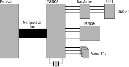
As the CS8900A has 100 pins and several different modes of operation, we won’t cover an entire schematic in one hit. Instead, we’ll work through each stage of a CS8900A’s design, and learn its functionality and use as we go. This discussion will be targeted at small, embedded application. Some of the more complicated aspects of the CS8900A, which are applicable to desktop PCs, will be left alone.
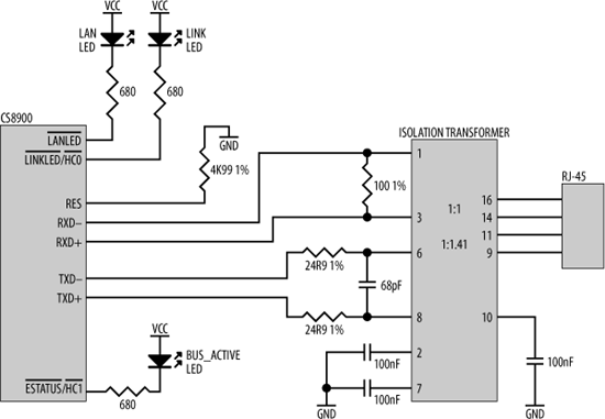
The CS8900A is connected to its 10BASE-T port through an isolation transformer. This transformer must have a winding ratio of 1:1 for the receiver, and a winding ratio n of 1:1.41 for the transmitter, if the CS8900A is used with a 5 V supply. If used with a 3.3 V supply, the transformer’s winding ratio for the transmitter must be 1:2.5. There are a number of manufacturers that make isolation transformers (packaged as chips) with these winding ratios, such as Valor, PCA, YCL, and Bel. The transmitter requires series-termination resistors of 24.9 Ω, ± 1%. The transmitter differential pair must be decoupled with each other using a 68 pF capacitor. A 100 Ω resistor (± 1%) is required in parallel between the receiver’s differential pair. The CS8900A can also directly drive LEDs, indicating Ethernet link status and bus and network activity. The CS8900A has an additional pin (RES) that requires a 4.99 kΩ (± 1%) pull-down resistor. Figure 12-6 shows the CS8900A connected to a 10BASE-T port.
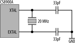
An external 20 MHz crystal provides timing for the CS8900A. The crystal is connected across the XTAL1 and XTAL2 pins, and each pin is bypassed to ground using 33 pF capacitors (Figure 12-7).
This Ethernet chip supports the 16-bit ISA bus architecture, the expansion bus found in older-model PCs. However, ISA can easily be adapted to work with a range of non-ISA processors. The CS8900A may therefore be implemented in a variety of computer systems without difficulty. The CS8900A also supports operation in 8-bit mode and thus can also be interfaced to microcontrollers with an 8-bit data bus, such as the AT90S8515 AVR. The CS8900A’s input ![]() is used to place the chip in 16-bit mode operation after reset. Any activity on
is used to place the chip in 16-bit mode operation after reset. Any activity on ![]() will place the CS8900A in 16-bit mode. The easiest way to ensure that there is activity on this input is simply to connect
will place the CS8900A in 16-bit mode. The easiest way to ensure that there is activity on this input is simply to connect ![]() to the processor’s address line, A0. As soon as the processor begins to use its bus, the activity will place the CS8900A in 16-bit mode. For 8-bit operation,
to the processor’s address line, A0. As soon as the processor begins to use its bus, the activity will place the CS8900A in 16-bit mode. For 8-bit operation, ![]() is tied to ground. When used in 8-bit mode, interrupts are disabled and the CS8900A’s status must be polled by software.
is tied to ground. When used in 8-bit mode, interrupts are disabled and the CS8900A’s status must be polled by software.
Before we look at the processor interface of the CS8900A, there are some important characteristics we need to note. On the CS8900A, RESET is active high. This can catch an unwary designer used to active-low resets. The reason that RESET is active high derives from the fact that this chip was designed principally for use in PCs, as Intel processors also have an active-high reset. The CS8900A’s reset may be driven by a digital output of a microcontroller so that it can be reset under software control. Alternatively, in systems where the CS8900A is to have a hardware-generated reset at the same time as the processor, the processor’s active-low reset signal must be inverted for the CS8900A. The CS8900A’s interrupt outputs (INTRQ0, INTRQ1, INTRQ2, INTRQ3) are also active high, and each must be inverted before connecting to an active-low interrupt input of a microprocessor.
Another consequence of its design for use in Intel-based systems is that the CS8900A is little endian in operation. When used in 16-bit mode with big-endian processors such as the MC68000 or the DSP56805, this endian difference is important. There are two possible solutions. The first is to simply byte-swap in software. Your code then changes the 16-bit word to little-endian format before writing to the CS8900A. And when reading from the CS8900A, the processor must byte-swap the retrieved 16-bit word prior to processing.
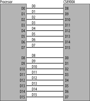
However, there is an old saying that you should never fix in software what you can correct in hardware. The second solution is simply to byte-swap the data bus between the processor and the CS8900A. D0:D7 of the processor is connected to D8:D15 of the CS8900A, and D8:D15 of the processor similarly go to D0:D7 of the CS8900A. In this way, the endian-ness is reversed by the actual circuit board, and the software never needs to know the difference (Figure 12-8).
The CS8900A has 20 address inputs. This may seem like a lot of address inputs for a peripheral, and it is. However, there is a reason. The CS8900A is principally an ISA-bus device, and the ISA bus supports separate memory and I/O memory spaces. Hence, the CS8900 has two separate processor interfaces. In one, it appears as part of the memory space of a processor and is accessed as though it were a memory device. A chip-select input
, ![]() , enables the CS8900A when it is used as a memory-mapped device. When it is used as a device within an I/O space, there is no externally generated chip select. Instead, devices mapped into the I/O space of an ISA bus are expected to do their own address decoding, and that is why the CS8900A has 20 address lines. Inside the CS8900A is an address decoder specifically for this chip. When the CS8900A is reset, it defaults to I/O address
, enables the CS8900A when it is used as a memory-mapped device. When it is used as a device within an I/O space, there is no externally generated chip select. Instead, devices mapped into the I/O space of an ISA bus are expected to do their own address decoding, and that is why the CS8900A has 20 address lines. Inside the CS8900A is an address decoder specifically for this chip. When the CS8900A is reset, it defaults to I/O address 0x00300. This address can be remapped under software control by writing to the appropriate register of the CS8900A. When used as an I/O-mapped device, ![]() is ignored and the CS8900A will respond to the appropriate address on its address inputs in conjunction with
is ignored and the CS8900A will respond to the appropriate address on its address inputs in conjunction with ![]() (I/O read) and
(I/O read) and ![]() (I/O write). You can use the CS8900A in I/O mode within a memory-mapped I/O system. The system address decoder includes the address allocation for the CS8900A but simply does not select it. What the system address decoder must do is ensure that no other device is selected when the address(es) corresponding to the CS8900A is being accessed.
(I/O write). You can use the CS8900A in I/O mode within a memory-mapped I/O system. The system address decoder includes the address allocation for the CS8900A but simply does not select it. What the system address decoder must do is ensure that no other device is selected when the address(es) corresponding to the CS8900A is being accessed.
The default setting for
the CS8900A is I/O mode operation. To use the CS8900A in memory-mapped mode, and therefore to have it recognize ![]() and its memory read (
and its memory read (![]() ) and memory write (
) and memory write (![]() ) inputs, the CS8900A must first be accessed as an I/O-mapped device and reconfigured in software. Therefore, to use the memory-mapped option, you still have to support the I/O-mapped addressing scheme to get to it! Therefore, it is much simpler to stick with the I/O-mapped mode and map this within your memory space as just described. If you’re using the CS8900A with a processor that has only a 16-bit address bus, simply tie the additional address inputs of the CS8900A to ground. The CS8900A’s default address of
) inputs, the CS8900A must first be accessed as an I/O-mapped device and reconfigured in software. Therefore, to use the memory-mapped option, you still have to support the I/O-mapped addressing scheme to get to it! Therefore, it is much simpler to stick with the I/O-mapped mode and map this within your memory space as just described. If you’re using the CS8900A with a processor that has only a 16-bit address bus, simply tie the additional address inputs of the CS8900A to ground. The CS8900A’s default address of 0x00300 may be inconvenient for use with some processors that already have internal I/O systems mapped within that region. An access to that address will be intercepted by the internal I/O and never reach the CS8900A. In such cases, it will be impossible to remap the CS8900A’s address through software. You will simply never reach the appropriate register. But there is a solution, and it lies within hardware. If you invert some of the address bits from the processor before they reach the CS8900A, you can perform the remapping automatically. The CS8900A still thinks it lies at address 0x00300, but to the processor it is accessed at a completely different address. Figure 12-9 shows an example of this for a processor with a 16-bit address bus.
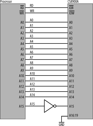
In this example, address bit A15 is inverted. So, when the processor accesses address 0x8300 (%1000 0011 0000 0000), this is converted to address 0x0300 (%0000 0011 0000 0000), which is recognized by the CS8900A.
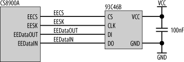
The CS8900A also has support for a serial EEPROM. This can be used to store CS8900A configuration information and the system’s unique Ethernet address. Note that this EEPROM is optional, as the host processor can store this data elsewhere in the system. Figure 12-10 shows the CS8900A interfaced to a configuration EEPROM. The interface is standard SPI, and the appropriate pins of the CS8900A are directly connected to the corresponding EEPROM pins. The only other component required is a decoupling capacitor for the EEPROM’s power-supply pin. The EEPROM interface is disabled in 8-bit mode, so the host processor must supply all configuration information.
Finally, any used inputs, such as the DMA signals (![]() ,
, ![]() , and
, and ![]() ),
), ![]() ,
, ![]() ,
, ![]() ,
, ![]() , AEN, and
, AEN, and ![]() should be tied inactive. These signals are not used in a typical embedded system.
should be tied inactive. These signals are not used in a typical embedded system.
[*] PARC is the Palo Alto Research Center (http://www.parc.com). For an interesting history of PARC (and the computer industry in general), read Robert X. Cringely’s Accidental Empires(HarperBusiness).