
Scenario: Shooting Trouble with IPX
This chapter starts with the same hands-on scenario you left off with at the Trouble Tickets at the end of the Chapter 3, “Shooting Trouble with IP.” Now is a good time to erase your configurations from previous labs and configure the Cisco router portion according to Figure 4-1. Rewiring is not necessary unless you want the practice.
NOTE
Like the preceding chapter, my lab uses the 2514, 2501, 3640, 3620, and 2516 Cisco routers; but yours can include any number of devices that have similar interfaces. See Appendix C, “Equipment Reference,” for the hardware used throughout the book.
The scenario goal is to configure the routers, servers, and clients using Internetwork Packet Exchange (IPX) as the routed protocol and IPX Routing Information Protocol (RIP) as the routing protocol to ensure end-to-end connectivity. More importantly, you need to document your steps and any problems along the way. Configure the routers starting with r1 first and work your way through r5.
Remember, however, that there is not always one right or wrong way to accomplish the tasks presented. The ability to obtain the end result using good practices is extremely important in any real-world network. Starting in Example 4-1, my troubleshooting and device configurations enable you to compare your work and perhaps see a different approach to obtaining the end result. Refer to Figure 4-1 as you continue to set up and troubleshoot.
Although I give you Figure 4-1, it is really a better practice to draw your own network diagram. Alternatively, use different-colored pens or pencils and add to the IP scenario from the preceding chapter. Label interfaces DCE or DTE and document device names, locations, Layer 2 and Layer 3 addresses, encapsulation types, routed and bridged protocols, access control lists (ACLs), and configuration files. Then verify full connectivity. Perform some simple ping ipx tests (as shown in Table 4-1), run show tech-support, and document everything. All of this gives you a starting point for normal baseline activity when your network is running well. Keep in mind that although NetWare 5.x and 6.x are native IP environments, I want you to concentrate on IPX-related baselining for this chapter.
| Isolating Problems | Commands and Symptoms |
|---|---|
| On the Novell client:
Physical cable and NIC Drivers, encapsulation, IPX address, other protocols Client software | ipxroute config
ipconfig /all (if also running IP) slist rconsole net config workstation net config server Use protocol analyzer to get addresses Network Neighborhood properties |
| On the Novell server:
Physical cable and NIC Drivers, encapsulation, IPX address, other protocols Server software | config
display servers display networks load monitor load inetcfg load startup.ncf load autoexec.ncf |
| On the Cisco router:
Ping Show Trace Debug Note: externalipx is the network number for the wire like an IP subnet number. internalipx is the network number internal to the Novell server. | ipx ping-default ?
ping ipx externalipx.mac-address ping ipx internalipx.0.0.1 show ipx interface brief show run interface e0 show ipx interface e0 show interfaces e0 show ipx servers show ipx route show protocols show ipx cache show ipx access-list show ipx traffic debug ipx routing ? debug ipx sap ? show tech-support |
| NetBIOS, sockets, and name resolution issues | See the IP checklist in Chapter 3 |
Table 4-1 gives you a layered yet divide-and-conquer approach to quickly spotting IPX client, server, or router issues. Just as with troubleshooting IP, understanding the problem is most of the battle. You may find problems such as workgroup/domain issues, client issues, file and print services issues, protocol issues, primary network login issues, browser service issues, license issues, Directory services issues, socket issues, NetWare Loadable Module (NLM) issues, version issues, application issues, and so on. If you can't communicate with your local router interface, however, it is a little difficult to communicate with a remote host. If you can communicate with one remote host but not another, check the configuration on the other remote host. With NetWare, the client configuration is intentionally very simple. If the client gets the frame type (encapsulation) correct, it will likely work.
NOTE
When shooting Novell trouble, remember to check the following websites for help: Cisco (www.cisco.com/tac), Novell (support.novell.com), Microsoft (www.microsoft.com/technet), and other hardware and software vendors.
Using the Figure 4-1 scenario diagram, configure r1 similar to what is in Example 4-1. Throughout the following examples, I have made a few careless mistakes that you may or may not make. I will troubleshoot them as required or when all my routers are configured. I am using the same terminal server configuration from Example 3-1 in Chapter 3.
NOTE
It is of extreme importance that you know the mode from which the command can be issued. At times I tend to issue global configuration commands in interface mode. This works just fine so long as you don't need help in the midst of the command. If you are unsure, however, type the command from the appropriate mode and make use of the Tab key and ? for help.
Example 4-1. r1 Configuration (2514)
Router>enable Router#configure terminal Router(config)#hostname r1 r1(config)#enable password donna r1(config)#line vty 0 4 r1(config-line)#login r1(config-line)#password donna r1(config-line)#interface serial 0 r1(config-if)#bandwidth 64 r1(config-if)#exit r1(config)#ipx ? % Unrecognized command r1(config)#end r1#show version Cisco Internetwork Operating System Software IOS (tm) 2500 Software (C2500-IS-L), Version 12.0(5), RELEASE SOFTWARE (fc1) ... System image file is "flash:c2500-i 00:03:53: %SYS-5-CONFIG_I: Configured from console by consoles-l.120-5.bin" cisco 2500 (68030) processor (revision L) with 2048K/2048K bytes of memory. ... 8192K bytes of processor board System flash (Read ONLY) Configuration register is 0x2102 |
NOTE
The system file image name ended up with text in the middle of it. This can be quite annoying in practice. Had I turned on logging synchronous, things like this would not have been interrupted. You should turn this command on for your configurations.
Obviously, there are some IPX issues with r1. Review the output and in particular the shaded areas. You may or may not have the same types of issues I am having. Hence you may be able to go a little further with your configuration. For now, if you are experiencing difficulty, you should continue on to configure r2 through r5. Actually, I am having similar issues with r2 recognizing IPX, so I moved on to r3 in Example 4-2.
Example 4-2. r3 Configuration (3640)
Router(config)#hostname r3 r3(config)#enable password donna r3(config-line)#line vty 0 4 r3(config-line)#login r3(config-line)#password donna r3(config-line)#interface serial 0/0 r3(config-if)#bandwidth 64 r3(config-if)#clock rate 64000 r3(config-if)#no shut r3(config-if)#ipx ? access-group Apply an access list to inbound or outbound packets accounting Enable IPX accounting on this interface ... rip-multiplier Multiple of RIP update interval for aging of RIP routes rip-response-delay Delay in answering RIP on this interface |
Example 4-2 clearly shows that IPX is available and has many options on r3, whereas r1 and r2 both did not recognize IPX commands at all. You could have verified this at either the interface or global configuration mode. Continue to configure IPX on r3 as in Example 4-3 and Figure 4-1.
Example 4-3. r3 Configuration (3640)
r3(config-if)#ipx network ? <1-FFFFFFFD> IPX network number (default route enabled) r3(config-if)#ipx network 0580 %Must give "ipx routing" command first r3(config-if)#exit r3(config)#ipx routing r3(config)#interface serial 0/0 r3(config-if)#ipx network 0580 r3(config-if)#no shut r3(config-if)#interface serial 0/1 r3(config-if)#bandwidth 64 r3(config-if)#clock rate 64000 r3(config-if)#ipx network 0564 r3(config-if)#no shut r3(config-if)#interface serial 0/2 r3(config-if)#bandwidth 64 r3(config-if)#clock rate 64000 r3(config-if)#ipx network 0548 r3(config-if)#no shut r3(config-if)#interface fastethernet 2/0 r3(config-if)#ipx network 0596 r3(config-if)#no shut r3(config-if)#interface serial 0/3 r3(config-if)#bandwidth 64 r3(config-if)#ipx network 1022 r3(config-if)#end r3#copy running-config startup-config |
Prior to configuring r4 and r5, take time to quickly review the shaded output in Example 4-3 emphasizing the IPX configuration on r3. The IP routing process is enabled by default, but IPX routing is not. In a practical environment, it is best practice to manually specify a node number for the serial interfaces to enable you to ping the serial interface using a known, predefined IPX node number. This is possible with the command ipx routing [node], where node could be something easy to remember such as 3.3.3 for your serial interfaces. Enabling IPX routing enables IPX RIP by default, as you will verify later with the show ipx route command. Quickly view the IPX network numbers, default encapsulation, and link status for r3 in Example 4-4.
Example 4-4. r3 Configuration (3640)
r3#show ipx interface brief Interface IPX Network Encapsulation Status IPX State Serial0/0 580 HDLC down [up] Serial0/1 564 HDLC down [up] Serial0/2 548 HDLC down [up] Serial0/3 1022 HDLC administratively down [up] Serial0/4 unassigned not config'd administratively down n/a ... Serial1/7 unassigned not config'd administratively down n/a FastEthernet2/0 596 NOVELL-ETHER up [up] |
Do not be concerned with the down status in Example 4-4 at this point for you really have only configured one router for IPX. Example 4-4 certainly illustrates that Cisco serial links default to High-Level Data Link Control (HDLC) encapsulation and that Ethernet defaults to Novell-Ether encapsulation (802.3).
NOTE
Frame types are potential lower-level IPX troubleshooting target areas in any Novell network where Cisco routers are involved. See the “Protocols and Packets” section for more detail.
Continue configuring your routers as in Example 4-5.
Example 4-5. r4 Configuration (3620)
Router(config)#hostname r4 r4(config)#enable password donna r4(config)#line vty 0 4 r4(config-line)#login r4(config-line)#password donna r4(config-line)#exit r4(config)#ipx routing r4(config)#interface serial 0/0 r4(config-if)#bandwidth 64 r4(config-if)#clock rate 64000 r4(config-if)#ipx network 1022 r4(config-if)#end r4#copy running-config startup-config r4#show ipx interface brief Interface IPX Network Encapsulation Status IPX State Ethernet0/0 unassigned not config'd administratively down n/a Serial0/0 1022 HDLC administratively down [up] Serial0/1 unassigned not config'd administratively down n/a |
The display for r5 in my lab is similar to r1 and r2, so I did not bother to display it at this point. Configure your r5, analyze any problems, fix them, and document the particulars. Depending on your exact lab setup, you may or may not have these same issues, and you may have different ones.
Example 4-6 gives you some hints as to the real problem. Use some of the tools you learned about in Chapter 2, “What's in Your Tool Bag?” and in other experiences to determine the issues and resolve the problems.
Example 4-6. Current IOS Versions in Flash
r5#show flash System flash directory: File Length Name/status 1 7567500 c2500-is-l.120-5.bin [7567564 bytes used, 9209652 available, 16777216 total] 16384K bytes of processor board System flash (Read ONLY) r4#show flash System flash directory: File Length Name/status 1 3971288 c3620-d-mz.113-9.T [3971352 bytes used, 12805864 available, 16777216 total] 16384K bytes of processor board System flash (Read/Write) r3#show flash System flash directory: File Length Name/status 1 6786288 c3640-js-mz.120-13.bin [6786352 bytes used, 9990864 available, 16777216 total] 16384K bytes of processor board System flash (Read/Write) r2#show flash System flash directory: File Length Name/status 1 7567500 c2500-is-l.120-5.bin [7567564 bytes used, 9209652 available, 16777216 total] 16384K bytes of processor board System flash (Read ONLY) r1#show flash System flash directory: File Length Name/status 1 7567500 c2500-is-l.120-5.bin [7567564 bytes used, 821044 available, 8388608 total] 8192K bytes of processor board System flash (Read ONLY) |
Now that you determined that the problem routers are all 2500 series and that the installed IOS supports only IP, you need to determine your next step. Another critical component is how much RAM and Flash you have on each of the problem routers. Table 4-2 displays my findings.
| Router | RAM in MB (show version) | Flash in MB (show flash) |
|---|---|---|
| r1 – 2514 | 2/2 | 8 |
| r2 – 2501 | 16/2 | 16 |
| r5 – 2516 | 14/2 | 16 |
r1 does not have much RAM. I had some RAM and Flash memory that I swapped over from a spare router so that r1 can run the same IOS as r2 and r5. Refer to Figure 4-2 or check out Cisco.com for any RAM/Flash upgrades and upgrade your lab as necessary. For the r1 IOS upgrade, upgrade the r1 Flash memory from 8 MB to 16 MB and download the required IOS file from the Cisco.com Software Center to the TFTP server directory.
NOTE
For the RAM/Flash upgrade, remove the slotted screw between the two pry slots on the router. Use a large flat-blade screwdriver to twist open the two-pry slots and remove the cover. I recommend you use a wrist strap to assist with static issues. Remove the old RAM/Flash, if required, and insert the new. My old RAM memory was 2 MB/2 MB, but my new RAM is 14 MB/2 MB, similar to what I have on r5 (as you can verify with a before and after show version). My old Flash memory was 8 MB, but my new one is 16 MB, which you can verify with a before and after show flash command.
The Flash is somewhat like a hard drive on a PC. Partition the Flash into one partition to hold a new IOS larger than 8 MB and verify the Flash memory upgrade on r1 as in Example 4-7. Figure 4-2 illustrates the actual hardware upgrade. Refer to Cisco.com and Appendix B, “Troubleshooting Resources,” for more information on Cisco hardware and software upgrades.
Example 4-7. Partition Flash on r1
r1(config)#partition flash ? <1-8> Number of partitions in device r1(config)#partition flash 1 ... r1>show version Cisco Internetwork Operating System Software IOS (tm) 2500 Software (C2500-IS-L), Version 12.0(5), RELEASE SOFTWARE (fc1) ... System restarted by power-on System image file is "flash:c2500-is-l.120-5.bin" cisco 2500 (68030) processor (revision L) with 14336K/2048K bytes of memory. ... 16384K bytes of processor board System flash (Read ONLY) Configuration register is 0x2102 r1>show flash System flash directory: File Length Name/status 1 7567500 c2500-is-l.120-5.bin [7567564 bytes used, 9209652 available, 16777216 total] 16384K bytes of processor board System flash (Read ONLY) |
NOTE
In Example 4-7, I first partitioned the Flash into one partition. I exited completely out of enable mode just to illustrate that many commands are available from user mode. For example, show version shows not only the IOS version, but also the amount of RAM memory right from user mode. Likewise, show flash displays that 16 MB of Flash memory is available with about 9 MB free from user mode.
The IOS Upgrade Planner is a very useful tool here. Select the Software Center from Cisco.com to locate the IOS Upgrade Planner in the Tools section. Unless I can't find the feature I need, my preference is to work with General Deployment (GD) code. 12.2 is not GD at the time of this writing; however, 12.1 and 12.0 are. You need something to support your hardware using at least IP and IPX as well as to enable you to experiment with other things in the scenarios and Trouble Tickets to come. For testing purposes in this book, use Enterprise Plus, if possible, to include more features. Although in a practical environment, you should standardize the code you use; it is fine to use different versions in the lab scenarios and Trouble Tickets in case there are more issues related to the versions you are using. Determine the best requirements for your own lab and upgrade the hardware and software as required.
NOTE
The Feature Navigator is very helpful in determining whether a given feature set or release level supports a given feature. Search by feature or release. Go to www.cisco.com/cgi-bin/Support/FeatureNav/FN.pl or search for “feature navigator” on Cisco.com to explore this tool.
Figure 4-3 displays the IOS Upgrade Planner. It displays the RAM and Flash memory requirements prior to download. Many times it gives you a link to critical issues (such as this one does with the Must Read link to Simple Network Management Protocol [SNMP] vulnerability information).
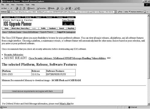
12.021a Enterprise Plus is GD. It requires a minimum of 6 MB RAM and 16 MB Flash as Figure 4-3 shows. Assuming you are logged in with your CCO account and have proper authorization, download the IOS now for use on r1, r2, and r5.
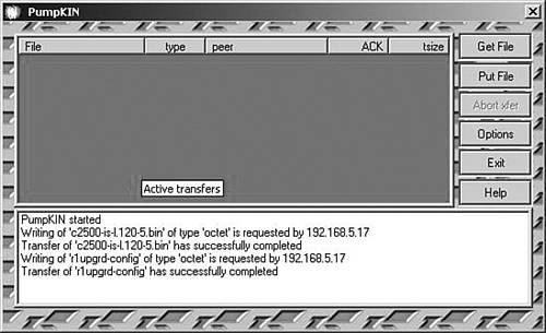
Next you should use a PC-based TFTP server for your r1 IOS and configuration backup. I used PumpKin (see Figure 4-4), but any TFTP server is fine. Although not necessary, this step is highly recommended and is a good practice. Certainly, this would be an easier task if your routers were still configured from the end of the IP chapter, but it is best you know how to do this starting from no configuration at all. Follow along in Example 4-8 to set up the necessary connectivity and IP address parameters to perform the backup.
NOTE
If you prefer, you can use just an Ethernet crossover and console cable from the TFTP PC to the router you are configuring at the time. Remember to save your software changes so they are still in effect when you reload the router.
Example 4-8. r1 IOS and Configuration Backup to TFTP
r1#show flash System flash directory: File Length Name/status 1 7567500 c2500-is-l.120-5.bin [7567564 bytes used, 821044 available, 8388608 total] 8192K bytes of processor board System flash (Read ONLY) r1#configure terminal r1(config)#interface ethernet 0 r1(config-if)#ip address 192.168.5.17 255.255.255.240 r1(config-if)#no shut r1(config-if)#end r1#copy running-config startup-config r1#ping 192.168.5.18 Type escape sequence to abort. Sending 5, 100-byte ICMP Echos to 192.168.5.18, timeout is 2 seconds: .!!!! Success rate is 80 percent (4/5), round-trip min/avg/max = 1/3/4 ms !!!first copy the old IOS to the tftp server r1#copy flash tftp Source filename []? c2500-is-l.120-5.bin Address or name of remote host []? 192.168.5.18 Destination filename [c2500-is-l.120-5.bin]? !!!!!!!!!!!!!!!!!!!!!!!!!!!!!!!!!!!!!!!!!!!!!!!!!!!!!!!!!!!!!!!!!! ... 7567500 bytes copied in 94.196 secs (80505 bytes/sec) !!!next copy the configuration file to the tftp server r1#copy running-config tftp Address or name of remote host []? 192.168.5.18 Destination filename [running-config]? r1upgrd-config !! 645 bytes copied in 5.544 secs (129 bytes/sec) |
Now that you have prepared the hardware and made your backups, upgrade the IOS using the copy tftp flash command similar to Example 4-9. Follow the generic steps in Appendix B to upgrade the IOS or use Cisco.com to research your exact requirements. Remember that the Flash is read-only on a 2500 series router because it is in fact a run-from-flash device. Use the config-register command to change to the boot helper mode (rxboot mode) so that you can change the Flash to read/write so that the router is ready to accept the new IOS. Remember that rxboot mode is an IP host implementation and will not work without the ip default-gateway statement unless the TFTP server is directly attached.
NOTE
Although I did not show the exact commands, my first couple of attempts to upgrade r1 failed. After I replaced the bad Flash memory, Example 4-9 worked fine. Obviously, this is an issue you may not have, but perhaps you can learn from my troubles. Look up any specific error messages you run into on Cisco.com to get more comfortable with the tools Cisco offers.
Example 4-9. r1 IOS Upgrade from TFTP Server
r1(config)#config-register 0x2101 r1(config)#end ... r1#reload Proceed with reload? [confirm] 00:18:07: %SYS-5-RELOAD: Reload requested ... r1(boot)#copy tftp flash System flash directory: File Length Name/status 1 5726508 c2500-i-l.120-9 [5726572 bytes used, 11050644 available, 16777216 total] Address or name of remote host [255.255.255.255]? 192.168.5.18 Source file name? c2500-js-l.120-21a.bin Destination file name [c2500-js-l.120-21a.bin]? Accessing file 'c2500-js-l.120-21a.bin' on 192.168.5.18... Loading c2500-js-l.120-21a.bin from 192.168.5.18 (via Ethernet0): ! [OK] Erase flash device before writing? [confirm] Flash contains files. Are you sure you want to erase? [confirm] Copy 'c2500-js-l.120-21a.bin' from server as 'c2500-js-l.120-21a.bin' into Flash WITH erase? [yes/no]y Erasing device... eeeeeeeeeeeeeeeeeeeeeeeeeeeeeeeeeeeeeeeeeeeeeeeeeeeeeeeeeee eeeee ...erased Loading c2500-js-l.120-21a.bin from 192.168.5.18 (via Ethernet0): |
CAUTION
Be careful when you come out of config mode from changing the configuration register and issue the reload command. In boot helper (rxboot) mode, it is important not to save the configuration. If you save at this point, some commands may be lost because the bootstrap software does not support the full command set.
Note how you were made to confirm more than once that you really wanted to erase Flash. Whether you need to erase depends on the amount of Flash installed and how much the IOS file or any configuration files use. A checksum is performed at the end of the copy to verify the upgrade.
Using a PC-based TFTP server is not the only method available for this task. So to get familiar with another method, you should set up r1 as a TFTP server serving the IOS image for r2 and r5 as in Example 4-10.
Example 4-10. Set Up r1 as a TFTP Server
r1(config)#tftp-server flash:c2500-js-l.120-21a.bin r1(config)#interface ethernet 1 r1(config-if)#ip address 192.168.5.33 255.255.255.240 r1(config-if)#no shut r1(config-if)#end r1#copy running-config startup-config |
Now that r1 is configured to serve up the IOS image, upgrade r2 using r1 over the common Ethernet link as in Example 4-11. Verify that the IOS is in Flash.
Example 4-11. r2 IOS Upgrade from r1 as a TFTP Server
r2(config)#interface ethernet 0 r2(config-if)#ip address 192.168.5.34 255.255.255.240 r2(config-if)#no shut r2(config-if)#end ... r2#copy running-config startup-config ... r2#copy tftp flash **** NOTICE **** Flash load helper v1.0 This process will accept the copy options and then terminate the current system image to use the ROM based image for the copy. Routing functionality will not be available during that time. If you are logged in via telnet, this connection will terminate. Users with console access can see the results of the copy operation. ---- ******** ---- Proceed? [confirm] Address or name of remote host []? 192.168.5.33 Source filename []? c2500-js-l.120-21a.bin Destination filename [c2500-js-l.120-21a.bin]? Accessing tftp://192.168.5.33/c2500-js-l.120-21a.bin... Erase flash: before copying? [confirm] 01:10:07: %SYS-5-RELOAD: Reload requested %SYS-4-CONFIG_NEWER: Configurations from version 12.0 may not be correctly understood. %FLH: c2500-js-l.120-21a.bin from 192.168.5.33 to flash ... System flash directory: File Length Name/status 1 7567500 c2500-is-l.120-5.bin [7567564 bytes used, 9209652 available, 16777216 total] Accessing file 'c2500-js-l.120-21a.bin' on 192.168.5.33... Loading c2500-js-l.120-21a.bin from 192.168.5.33 (via Ethernet0): ! [OK] Erasing device... eeeeeeeeeeeeeeeeeeeeeeeeeeeeeeeeeeeeeeeeeeeeeeeeeeeee eeeeeeeeeee ...erased Loading c2500-js-l.120-21a.bin from 192.168.5.33 (via Ethernet0): |
Example 4-11 shows how Flash load helper was invoked to copy the image, which included the appropriate configuration register and reboot requirements. The new IOS file is now in Flash. Appendix B offers more information on router bootup and configuration register parameters.
Prepare r5 for IPX by upgrading the IOS using r1 as a TFTP server over the 64 kbps serial link as in Example 4-12. Perform the upgrade from boot helper (rxboot) mode.
Example 4-12. Preparing r1 and r5 for the Upgrade
r1(config)#interface serial 0 r1(config-if)#ip address 10.1.1.1 255.255.255.0 r1(config-if)#no shut r1(config-if)#end r1#copy running-config startup-config r5(config)#interface serial 0 r5(config-if)#clock rate 64000 r5(config-if)#ip address 10.1.1.2 255.255.255.0 r5(config-if)#no shut r5(config-if)#exit r5(config)#config-register 0x2101 r5(config)#exit r5#reload System configuration has been modified. Save? [yes/no]: y ... 16384K bytes of processor board System flash (Read/Write) |
The shaded output in Example 4-12 illustrates how to change r5 to rxboot mode so that the Flash is read/write. Now you can copy the new IOS from r1 to r5 as in Example 4-13.
Example 4-13. r5 IOS Upgrade from r1 as a TFTP Server
r5(boot)>enable r5(boot)#copy tftp flash System flash directory: File Length Name/status 1 7567500 c2500-is-l.120-5.bin [7567564 bytes used, 9209652 available, 16777216 total] Address or name of remote host [255.255.255.255]?10.1.1.1 Source file name? c2500-js-l.120-21a.bin Destination file name [c2500-js-l.120-21a.bin]? Accessing file 'c2500-js-l.120-21a.bin' on 10.1.1.1... Loading c2500-js-l.120-21a.bin from 10.1.1.1 (via Serial0): ! [OK] Erase flash device before writing? [confirm] Flash contains files. Are you sure you want to erase? [confirm] Copy 'c2500-js-l.120-21a.bin' from server as 'c2500-js-l.120-21a.bin' into Flash WITH erase? [yes/no]y Erasing device... eeeeeeeeeeeeeeeeeeeeeeeeeeeeeeeeeeeeeeeeeeeeeeeeeeeeeeee eeeeeeee ...erased Loading c2500-js-l.120-21a.bin from 10.1.1.1 (via Serial0): !!!!!!!!!!!!!!!!!!!!!!!!!!!!!!!!!!!!!!!!!!!!!!!!!!!!!!!!!!!!!!!!!!!!!!!! ... [OK - 10253564/16777216 bytes] Verifying checksum... OK (0xFA32) Flash copy took 0:28:32 [hh:mm:ss] r5(boot)#configure terminal r5(boot)(config)#config-register 0x2102 r5(boot)(config)#end r5(boot)#reload System configuration has been modified. Save? [yes/no]: n Warning: Attempting to overwrite an NVRAM configuration written by a full system image. This bootstrap software does not support the full configuration command set. If you write memory now, some configuration commands may be lost. ... Cisco Internetwork Operating System Software IOS (tm) 2500 Software (C2500-JS-L), Version 12.0(21a), RELEASE SOFTWARE (fc1) ... cisco 2516 (68030) processor (revision J) with 14336K/2048K bytes of memory. Processor board ID 02959130, with hardware revision 00000000 ... 16384K bytes of processor board System flash (Read ONLY) Press RETURN to get started! |
The r5 IOS Flash copy took 28 minutes 32 seconds to complete, which is quite a bit of time difference between this 64k link and the 10-MB Ethernet from the previous example. As with anything else, more is normally better. The faster bandwidth is the better download method if in fact you have a choice. Note the shaded message about the NVRAM overwrite that I previously warned you about if you save while in rxboot mode.
NOTE
I had you use different methods to upgrade the IOS on your routers just so you would become familiar with the different methods. However, all of my methods involved the TFTP server being local to the device you were copying to. If the TFTP server is not directly connected, you need to configure the ip default-gateway statement on your routers.
Now that all your routers are IPX-capable and more, configure the rest. Remove any IP configuration on the routers and configure IPX; enable password, enable secret, and telnet passwords on all routers as in Example 4-14.
NOTE
Proper planning would certainly have eliminated the IOS upgrade in the midst of trying to configure IPX. This goes back to methodology and knowing your requirements up front. It is critical for you to keep that in mind for practical application.
Example 4-14. r1 IPX Configuration
r1(config)#line console 0 r1(config-line)#logging synchronous r1(config-line)#exit r1(config)#enable password donna r1(config)#enable secret donna The enable secret you have chosen is the same as your enable password. This is not recommended. Re-enter the enable secret. r1(config)#line vty 0 4 r1(config-line)#login r1(config-line)#password donna r1(config-line)#exit r1(config)#ipx routing r1(config)#interface ethernet 0 r1(config-if)#description r1e0 to hosta and hostb r1(config-if)#ipx network 0516 r1(config-if)#no ip address r1(config-if)#no shut r1(config-if)#interface ethernet 1 r1(config-if)#description r1e1 to r2e0 r1(config-if)#ipx network 532 r1(config-if)#no ip address r1(config-if)#no shut r1(config-if)#interface serial 1 r1(config-if)#description r1s1 to r3s0/0 r1(config-if)#ipx network 580 r1(config-if)#no ip address r1(config-if)#bandwidth 64 r1(config-if)#no shut r1(config-if)#interface serial 0 r1(config-if)#description r1s0 to r5s0 r1(config-if)#ipx network 1011 r1(config-if)#bandwidth 64 r1(config-if)#no ip address r1(config-if)#no shut r1(config-if)#end r1#copy running-config startup-config |
On r1, I put in the enable password and enable secret password. The IOS recommended I didn't make them the same password because of security, but it took the password anyway. The show running-config command in Example 4-15 shows the enable password in clear text, so it is pretty easy to guess the enable secret in this example. Verify this and the other IPX-specific parameters as in Example 4-15. Notice how the IOS puts a 5 before the enable secret password for the MD5-type of encryption.
NOTE
Most people insist on typing enable secret password when the command is actually just enable secret. A good guess for the enable secret password is spacebar password or spacebar password spacebar or some combination of that followed by the word the person thinks is the password. If you are not such a good guesser, Cisco has great documentation on password recovery at www.cisco.com/warp/public/474/index.shtml. Check out this website, Cisco.com, and Appendix B for more detail.
Example 4-15. r1 Running Configuration
r1#show running-config Building configuration... Current configuration: version 12.0 service timestamps debug uptime service timestamps log uptime no service password-encryption hostname r1 enable secret 5 $1$m0s2$Pq/6.NpOCSzhbQlNy.cnG/ enable password donna ip subnet-zero ipx routing 0000.0c8d.6705 interface Ethernet0 description r1e0 to hosta and hostb no ip address no ip directed-broadcast no ip route-cache no ip mroute-cache ipx network 516 interface Ethernet1 description r1e1 to r2e0 no ip address no ip directed-broadcast no ip route-cache no ip mroute-cache ipx network 532 interface Serial0 description r1s0 to r5s0 bandwidth 64 no ip address no ip directed-broadcast no ip route-cache no ip mroute-cache ipx network 1011 interface Serial1 description r1s1 to r3s0/0 bandwidth 64 no ip address no ip directed-broadcast no ip route-cache no ip mroute-cache ipx network 580 ip classless tftp-server flash:c2500-js-l.120-21a.bin line con 0 logging synchronous transport input none line aux 0 transport input all line vty 0 4 password donna login end |
Notice that both the enable password and enable secret passwords are in the configuration. When the enable and enable secret passwords are configured, the enable secret always takes precedence. Feel free to make the enable and enable secret passwords different sometime to prove that theory. In a practical sense, just use enable secret.
Look at the shaded IPX routing line. There is a number after it that you did not configure. If you were to issue the show ipx interface ethernet 0 command, you would see the IPX address as 516.0000.0c8d.6705. Because you did not specify the optional node parameter when you configured IPX routing, the router configured it for you. It borrowed the first available Ethernet MAC address for this purpose. Duplication is not a problem here because the external network number (wire number) differs for each link. Because Novell uses a MAC address for the node, you must either configure it or accept the default for your serial interfaces. Although you may not see the relevance of configuring your own node address for the serial links now, it is best practice to do so (as you will experiment with in the Trouble Tickets). Compare the IPX network numbers in the configuration against Figure 4-1 to see that the leading 0s are suppressed. Notice also that r1 is still configured as a TFTP server for the IOS image. Now configure r2 per Figure 4-1 as in Example 4-16.
NOTE
Because you are familiar with hostnames, passwords, logging synchronous, and such, I am only showing the IPX global and interface configurations for the rest of the routers. Assume a bandwidth of 64 kbps and clock rate of 64000 unless specifically mentioned to be something else.
Example 4-16. r2 IPX Configuration
r2(config)#ipx routing r2(config)#interface ethernet 0 r2(config-if)#description r2e0 to r1e1 r2(config-if)#ipx network 532 r2(config-if)#no ip address r2(config-if)#no shut r2(config-if)#interface serial 1 r2(config-if)#description r2s1 to r3s0/2 r2(config-if)#ipx network 548 r2(config-if)#no ip address r2(config-if)#bandwidth 64 r2(config-if)#no shut r2(config-if)#interface serial 0 r2(config-if)#description r2s0 to r3s0/1 r2(config-if)#ipx network 564 r2(config-if)#no ip address r2(config-if)#bandwidth 64 r2(config-if)#no shut r2(config-if)#end r2#copy running-config startup-config |
Now configure r3 per Figure 4-1 as in Example 4-17.
Example 4-17. r3 IPX Configuration
r3(config-line)#ipx routing r3(config)#interface serial 0/0 r3(config-if)#description r3s0/0 to r1s1 r3(config-if)#ipx network 580 r3(config-if)#no ip address r3(config-if)#bandwidth 64 r3(config-if)#clock rate 64000 r3(config-if)#no shut r3(config-if)#interface serial 0/1 r3(config-if)#description r3s0/1 to r2s0 r3(config-if)#bandwidth 64 r3(config-if)#clock rate 64000 r3(config-if)#ipx network 564 r3(config-if)#no ip address r3(config-if)#no shut r3(config-if)#interface serial 0/2 r3(config-if)#description r3s0/2 to r2s1 r3(config-if)#bandwidth 64 r3(config-if)#clock rate 64000 r3(config-if)#ipx network 548 r3(config-if)#no ip address r3(config-if)#no shut r3(config-if)#interface serial 0/3 r3(config-if)#description r3s0/3 to r4s0/0 r3(config-if)#bandwidth 64 r3(config-if)#ipx network 1022 r3(config-if)#no ip address r3(config-if)#no shut r3(config-if)#interface fastethernet 2/0 r3(config-if)#description r3fa2/0 to hostc r3(config-if)#ipx network 596 r3(config-if)#no ip address r3(config-if)#no shut r3(config-if)#end r3#copy running-config startup-config |
Now configure r4 per Figure 4-1 as in Example 4-18.
Example 4-18. r4 IPX Configuration
r4(config)#ipx routing r4(config)#interface serial 0/0 r4(config-if)#description r4s0/0 to r3s0/3 r4(config-if)#ipx network 1022 r4(config-if)#no ip address r4(config-if)#bandwidth 64 r4(config-if)#clock rate 64000 r4(config-if)#no shut r4(config-if)#end r4#copy running-config startup-config |
Now configure r5 per Figure 4-1 as in Example 4-19.
Example 4-19. r5 IPX Configuration
r5(config)#ipx routing r5(config)#interface serial 0 r5(config-if)#description r5s0 to r1s0 r5(config-if)#bandwidth 64 r5(config-if)#clock rate 64000 r5(config-if)#ipx network 1011 r5(config-if)#no ip address r5(config-if)#no shut r5(config-if)#end r5#copy running-config startup-config |
Now that IPX is configured on the routers in your lab, use Example 4-20 as a guide to test routers 1 through 5. Compare the output to your IPX scenario drawing to spot any issues and to document the network.
Example 4-20. r1 Testing
r1>show ipx interface brief Interface IPX Network Encapsulation Status IPX State Ethernet0 516 NOVELL-ETHER up [up] Ethernet1 532 NOVELL-ETHER up [up] Serial0 1011 HDLC up [up] Serial1 580 HDLC up [up] r1#show ipx route Codes: C - Connected primary network, c - Connected secondary network S - Static, F - Floating static, L - Local (internal), W - IPXWAN R - RIP, E - EIGRP, N - NLSP, X - External, A - Aggregate s - seconds, u - uses, U - Per-user static 7 Total IPX routes. Up to 1 parallel paths and 16 hops allowed. No default route known. C 516 (NOVELL-ETHER), Et0 C 532 (NOVELL-ETHER), Et1 C 580 (HDLC), Se1 C 1011 (HDLC), Se0 R 548 [02/01] via 532.0000.0c38.a05d, 45s, Et1 R 564 [02/01] via 532.0000.0c38.a05d, 45s, Et1 R 1022 [07/01] via 580.00b0.6481.e300, 45s, Se1 r1#show ipx servers r1#show protocols Global values: Internet Protocol routing is enabled IPX routing is enabled Ethernet0 is up, line protocol is up IPX address is 516.0000.0c8d.6705 Ethernet1 is up, line protocol is up IPX address is 532.0000.0c8d.6706 Serial0 is up, line protocol is up IPX address is 1011.0000.0c8d.6705 Serial1 is up, line protocol is up IPX address is 580.0000.0c8d.6705 |
The IOS commands used in Example 4-20 prove quite helpful for spotting Novell issues. You have been using show ipx interface brief throughout this chapter to get a basic idea of the networks, encapsulation types, and status thereof. The next command, show ipx route, is extremely helpful. For instance, count the wires on your Figure 4-1 diagram. I count eight wires, but only see seven networks on the router display. Looking at the show ipx route display and my drawing helps me to determine that the missing network is 596. Router 2 is a little closer to the destination network. Investigate whether it can see network 596 (as in Example 4-21). No IPX servers are listed yet, and the output of show protocols is extremely helpful to inform you that IPX routing is in fact on, but better yet, all your node addresses are in one place.
Example 4-21. r2 Testing
r2#show ipx route ... 7 Total IPX routes. Up to 1 parallel paths and 16 hops allowed. No default route known. C 532 (NOVELL-ETHER), Et0 C 548 (HDLC), Se1 C 564 (HDLC), Se0 R 516 [02/01] via 532.0000.0c8d.6706, 0s, Et0 R 580 [02/01] via 532.0000.0c8d.6706, 0s, Et0 R 1011 [02/01] via 532.0000.0c8d.6706, 0s, Et0 R 1022 [07/01] via 564.00b0.6481.e300, 45s, Se0 |
The problem still exists, for r2 does not see any more networks than r1 does. Because the missing network is off of r3, move your testing closer to the problem (as I do in Example 4-22). A layered troubleshooting approach is critical here, because the real problem in my lab is a loose cable on r3 fa2/0, which completely isolates network 596. Pull your cable or completely power off hostc to simulate the issue. Assuming you don't have a lot of network activity, you might also find it helpful to turn on debug ipx routing events to watch what is happening with the routing updates.
Example 4-22. r3 Testing
r3#show interfaces fastethernet 2/0 FastEthernet2/0 is up, line protocol is down Hardware is AmdFE, address is 00b0.6481.e300 (bia 00b0.6481.e300) ... r3#debug ipx routing ? activity IPX RIP routing activity events IPX RIP routing events r3#debug ipx routing events IPX routing events debugging is on r3#!!!plug in the cable and/or turn hostc on 03:48:35: IPXRIP: 548 FFFFFFFF not added, entry in table is static/ connected/internal 03:48:35: IPXRIP: 564 FFFFFFFF not added, entry in table is static/ connected/internal 03:48:36: IPXRIP: positing full update to 580.ffff.ffff.ffff via Serial0/0 (broadcast) 03:48:47: %LINEPROTO-5-UPDOWN: Line protocol on Interface FastEthernet2/0, changed state to up 03:48:47: IPXRIP: Marking network 596 FFFFFFFF for Flash Update 03:48:47: IPXRIP: General Query src=596.00b0.6481.e300, dst=596.ffff.ffff.ffff, packet sent (via FastEthernet2/0) 03:48:47: IPXRIP: positing flash update to 580.ffff.ffff.ffff via Serial0/0 (broadcast) 03:48:47: IPXRIP: positing flash update to 564.ffff.ffff.ffff via Serial0/1 (broadcast) 03:48:47: IPXRIP: positing flash update to 548.ffff.ffff.ffff via Serial0/2 (broadcast) 03:48:47: IPXRIP: positing flash update to 1022.ffff.ffff.ffff via Serial0/3 (broadcast) 03:48:47: IPXRIP: positing flash update to 596.ffff.ffff.ffff via FastEthernet2/0 (broadcast) 03:48:47: IPXRIP: positing full update to 596.ffff.ffff.ffff via FastEthernet2/0 (broadcast) 03:48:47: IPXRIP: suppressing null update to 596.ffff.ffff.ffff (FastEthernet2/0) 03:48:47: IPXRIP: 596 FFFFFFFF not added, entry in table is static/ connected/internal ... r3#undebug all All possible debugging has been turned off r3#show ipx route ... 8 Total IPX routes. Up to 1 parallel paths and 16 hops allowed. No default route known. C 548 (HDLC), Se0/2 C 564 (HDLC), Se0/1 C 580 (HDLC), Se0/0 C 596 (NOVELL-ETHER), Fa2/0 C 1022 (HDLC), Se0/3 R 516 [07/01] via 580.0000.0c8d.6705, 25s, Se0/0 R 532 [07/01] via 564.0000.0c38.a05d, 56s, Se0/1 R 1011 [07/01] via 580.0000.0c8d.6705, 25s, Se0/0 r3# |
When you fixed the issue, a Flash update was immediately sent to update the routing tables. Network 596 now displays, so continue testing and troubleshooting r4 and r5.
All eight networks are present in r1 through r5, but when did you turn on RIP? Actually you never turned on IPX RIP; it comes automatic with IPX. This was definitely not the case in the Chapter 3 with IP RIP.
This is a great time to further document your scenario drawing. As you can tell from the previous examples, show protocols is great for address documentation. I often log this type of data to a log file with SecureCRT. I just choose Log Session from the File menu, turn it off when I have captured the appropriate data, and rename the SecureCRT session file. Alternatively, you can use the HyperTerm Transfer menu to capture text. For more IPX-related commands and information, familiarize yourself with show tech-support in an IPX environment (as I do in Example 4-23). Because you are familiar with many of the individual commands, much of the output is omitted.
Example 4-23. show tech-support in an IPX Environment
r1#show tech-support ------------------ show version ------------------ ------------------ show running-config ------------------ ------------------ show controllers ------------------ ------------------ show stacks ------------------ ------------------ show interfaces ------------------ ------------------ show region ------------------ ------------------ show process memory ------------------ ------------------ show process cpu ------------------ ------------------ show buffers ------------------ |
Now that this chapter's IPX lab scenario is configured from the router point of view, turn your attention to the following section, “Protocols and Packets.” It starts with a layered approach to the Novell NOS to review IPX concepts, symptoms, problems, and action plans. There are more walk-through scenarios and practical Trouble Tickets for you to explore, because, after all, you learn more by doing; besides you need to configure your Novell server and clients. For those who do not have equipment handy or the desire to work with Novell anymore, I will continue to include many relevant figures and examples so that you, too, can shoot trouble with IPX. However, you will find that I am a firm believer in letting routers route and servers serve.