Shooting Trouble with VLANs
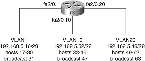
This section is for you if you have ever whispered to yourself, “Where the heck are my VLANs?” Actually, the entire chapter is for you. Shooting trouble with VLANs requires that you understand Physical and Data Link Layer targets and well as normal switch and router operations. A physical and logical map is not just something nice to have. It is so important that I want you to take time now to draw a Layer 2 and Layer 3 map of your environment as it is. My drawings are in Figure 7-8 and Figure 7-9.
Figure 7-8. Chapter 7 Physical Map (VLANs)

Figure 7-9. Chapter 7 Logical Map (VLANs)

Now that you have your maps, make sure you have copies of the configuration on your routers and switches.
Regardless of the issue, you must continue to follow a consistent methodology, such as those suggested in the first part of the book, to assist you in isolating fault domains. It is probably not a bad idea to go back and review the Ethernet and switch beginning checklists and ending sections on shooting trouble. They all allude to the fact that interfaces (ports) are the main Data Link Layer targets. However, VLAN-to-VLAN communications involve routing, so it would be to your advantage to go back and review the routing chapter as well. Look at your pictures and other documentation to assist with end-to-end troubleshooting.
As with anything else, you may have a software or hardware bottleneck. Know the limitations of your transport and your devices. Use your CCO account on Cisco.com to assist with specific error messages and to take a look at sample configurations. Again, all of this systematic troubleshooting relates back to the OSI model. Do you have power? Are the power supply and fans running? Are devices turned on? Do they have link lights? Green means go. Check Layer 2 encapsulations, speed, and duplex settings. How about your route tables. Is there any filtering that is blocking what you are trying to do? Just keep moving up the stack.
With VLANs in particular, beware of adding new switches and the results of the default VTP server mode. Use some of the diagnostic commands, such as the following:
show cdp neighbors
show ip interface brief
show vlan
show vlan brief
show vtp ?
show spanning-tree/show spantree
show interface/show port
show arp
show ip cache (show ip cef / show adjacency)
show vlan statistics
The debug vlan packet command displays only packets with a VLAN ID that the router is not configured to support. This is good for address and encapsulation issues. Issue debug span ? and compare to the CatOS show spantree to view STP bridge protocol data units (BPDUs) in action. Alternatively, experiment with the set trace commands in CatOS, which are not the same as but appear to resemble debug in IOS. Again, practice a limited amount of safe debug in a practical environment.
Once again it is time for the chapter Trouble Tickets. The plan here is to give you several things to do, let you make mistakes and fix some things on your own, and to introduce other problems that you should have some experience with as a support person.
