
CHAPTER 9
Structural and Mechanical Considerations
In this chapter, you will learn about
• Building codes and issues that have an impact on AV design
• Equipment mounting requirements
• Mounting requirements in racks and how to calculate power consumption and heat loads
• Heating, ventilation, and air conditioning (HVAC) and fire safety issues that impact AV systems
• The Audiovisual Systems Energy Management standard and how you can use it to conserve energy in your AV systems
In a building, there is a limited amount of space for infrastructure, and AV systems aren’t the only types of systems that need to be installed. There are HVAC, fire suppression, electrical, lighting, and other systems. And like AV systems, these others comprise not only the actual equipment but also power, cabling, cable pathways, and more. To ensure the systems integrate seamlessly, coordinating the AV design with the members of the architect, engineer, and construction (AEC) team is paramount. Moreover, the standards of all applicable trade groups must be carefully considered and effectively communicated.
This chapter—divided into mechanical and structural topic areas—will discuss various infrastructure elements that are important to your design so you can better communicate with others on the design team. We start by delving into rules and regulations governing the design of the structural and mechanical elements of an AV design.
Codes and Regulations
Building codes exist to protect life and safety. They define standards for the design and construction of electric systems, fire protection, and structural systems. The regulatory bodies tasked with overseeing the construction of public spaces want to know the answers to the following questions:
• How many people should we permit within a space?
• How much room is required for exiting?
• How should we protect the people during an emergency situation?
• How should people be protected from accidental electrical shock?
• What construction materials are appropriate (and inappropriate)?
There are many code considerations an AV professional should learn. Most codes are logical and serve a good purpose. Even if they are not enforced in your area, you may want to consider codes as best practices. The following are some examples:
• The Health and Safety Executive in the United Kingdom has a regulation that limits the exposure of employees to certain sound pressure levels. Local Authority Circular 59/5: Advice on the Enforcement of the Noise at Work Regulations 1989 in Leisure Premises (Where Recorded or Amplified Music is Played) states that employees should not be subjected to more than an average of 85 A-weighted decibels (dBA) over an eight-hour period without some protective action taken.
• The National Fire Protection Association (NFPA) publishes NFPA 101B: Code for Means of Egress from Buildings and Structures. This code provides guidance on the width of aisles for typical seating, the width of exit rows, and furniture arrangement, which are all critical to AV design.
• The Americans with Disabilities Act (ADA) offers guidelines to ensure all people, regardless of disability, have the same experience in a space. Australia’s Disabilities Act and the United Kingdom’s Disabilities Discrimination Act are similar to the U.S. guidelines.
First we’ll go into more depth on specific design elements that consider the needs of people with disabilities. Then we’ll discuss some of the electrical and construction codes that affect AV design.
Designing for Equal Access
Many regions, including the United States, have laws or codes that prohibit discrimination based on disability. These laws often impact structural considerations in new construction. In the United States, the Americans with Disabilities Act identifies a range of other construction standards that AV designers must be aware of when laying out a room. For example, everyone should have equal access to a space, and passageways must be kept clear of protruding elements that could interfere with a person’s passage through the space.
When it comes to designing for equal access, you will need to refer to the different governing bodies in your location. Governing bodies provide building code provisions for equal access to people with disabilities. For example, the ADA states that the same experience must be provided to all people. However, it does not detail the specific solutions required to meet that requirement.
In the case of AV systems, guidelines dictate that every presenter or end user must have access to the same control functions. This typically means that operator controls should be between 15 and 54 in above the floor, depending on whether someone in a wheelchair is directly in front of the equipment or approaching from the side. This allows a person in a wheelchair to insert media or operate controls. If the equipment must be approached from the front because a wheelchair cannot come beside it, then the access points should be between 15 and 48 in (380 and 1220 mm) high (see Figure 9-1). See the “Ergonomics” section in this chapter for more information.

Figure 9-1 ADA guidelines for access to control functions
The guidelines also dictate that every presenter must have access to all sources, including slides, video, and recordings. For example, if there is fixed seating and an audio system, an assistive listening system should be provided for the hearing impaired.
The ADA also recommends certain design guidelines related to head and aisle clearance (Figure 9-2). For example, equipment, such as a display, should protrude no farther than 4 in (101.6 mm) from a wall. And when hanging screens, projectors, or other devices from a ceiling, it’s important to note that ADA guidance states that 80 in (2.03 m) is the minimum height for any passageway.

Figure 9-2 ADA guidelines for head and aisle clearance
Electric and Building Codes
Codes are an extensive compilation of minimum standards for construction purposes. They protect the health and safety of people who use or occupy buildings and structures. Typically, the authors of codes have no enforcement power. They are merely experts offering their opinions. A governing or ruling body takes these suggestions and adopts them as their own.
Some examples include the NFPA and the International Code Council (ICC), authors of guidelines on the construction and occupancy of buildings. The NFPA authors the National Electric Code (NEC), a well-respected source of electrical installation and usage guidelines for the United States. The ICC develops the International Building Code (IBC), a reference work for construction materials and practices.
A country may adopt uniform rules that cover any or all of these items. For instance, the Australian Building Codes Board is a joint initiative of all levels of government in Australia. Its mission is to provide guidance for design, construction, and use of buildings through nationally consistent building codes, standards, regulatory requirements, and regulatory systems.
A country may also choose to let smaller governing bodies make the rules. This is the case in the United States. The individual states can develop their own codes, and regions and cities may add their own. They typically reference and adopt portions of the NEC or IBC material. You will revisit electric and building codes in Chapter 10.

NOTE Make sure you are aware of the codes at work in your area, as prescribed by the authority having jurisdiction (AHJ), or regional regulatory authority. Ignorance is never an excuse. In some cases, several conflicting codes from jurisdictions may overlap. In a case like this, it is important that you follow the most restrictive code.
Mounting Considerations
The building structure is the part of a building that is capable of supporting other materials. This may be structural steel, concrete, or wood trusses. Keep in mind, there are portions of the building structure that you can see, but they may not be true structural components.
You can have the perfect design with all the right equipment to fulfill a client’s needs, but if the building structure can’t sustain the weight of mounted AV components, the installation will be unsafe. To create a plan for mounting AV devices as necessary, ask the following questions at the beginning of the project:
• Will the building structure hold each piece of equipment?
• Will the mounted support system hold each piece of equipment?
To answer these questions, you should determine what type of building material is behind finished walls and ceilings. What looks like a solid wall may, in fact, be old plaster with no structural integrity.
Mounting Options
You have a few options for mounting AV equipment in a space—on the floor, wall, or overhead. This allows you to offer alternatives depending on the structure of the room or building.
Floor Mounting
Floor mounting is the simplest form of mounting because gravity is working in your favor. The equipment is mounted to the floor (see Figure 9-3), simultaneously ensuring that the equipment is securely attached and protected from theft or misuse.

Figure 9-3 Bolts hold rear-projection mirror mounts in place.
Alignment of a rear-projection mirror assembly takes many hours of labor. It needs to be performed in a way that prevents accidental movement and resulting damage. Once the alignment is complete, the assembly can be attached to the floor permanently. However, this task should not be performed without the building owner’s permission.
Wall Mounting
When it comes to mounting equipment to a wall, an AV designer has to consider several structural elements, in addition to the equipment weight.
Suppose you intend to mount a remote-controlled video camera to the wall of a training room. The camera assembly weighs 30 lb (13.6 kg), and the mounting bracket offers a footprint of 6 by 6 in (152.4 by 152.4 mm) for support.
It may seem like attaching the mounting bracket to the wall is a simple solution, but there are other considerations.
• Can the wall withstand the load of this camera assembly? You should investigate the construction of the wall.
• Will the weight of the camera on the end of the mounting bracket pull the assembly out of the wall? The camera suspended from the wall on a bracket creates a lever.
One of the most important aspects of wall mounting is to include proper blocking. Blocking is the support system or construction material that is added to the wall, typically before the wall finish is applied (see Figure 9-4).

Figure 9-4 Blocking for wall-mounted equipment
The general contractor may install heavy wood into the wall assembly across three or more studs prior to applying sheet rock or drywall. Once the finish is applied to the wall, the blocking is invisible to the eye. This cannot be accomplished without planning and coordination among the AV designer, architect, and builder.
Overhead Mounting
Any time you suspend or hang overhead equipment, you need to think about supporting the equipment’s weight. And because you always want to attach mounting support to the building structure and not the ceiling itself, you’re less concerned with the type of ceiling in a space than what’s behind it. How is the building constructed? Is it poured, pan-style concrete? Is it post-tension construction, in which smooth concrete includes high-tension cables running through it for support?
Construction stability is vital. If someone on your project drills through a cable in post-tension flooring, the cable could snap with such great force that it tears off the outside of the building. Always verify the depth and location of these cables with the building owner before attempting to mount equipment to a ceiling or floor. If this information is not available for the building, then an X-ray of the proposed drilling or trenching site must be conducted and interpreted by specialists.
When you’re planning for mounting to a wall or overhead, check the load limit in the mounting equipment specifications to find out the weight at which the item will structurally fail.
Load Limit
Load limit is an important part of AV equipment’s specifications. One element of the load limit is the safe working load (SWL), or a similar rating called the working load limit (WLL), which is the weight that must not be exceeded. Note that the load factor specified for the mount refers only to the mount and not to the bolts or any other components used in mounting. Each individual component has its own load factor, and you should be able to identify the weakest link.
If you exceed the load limit, your device won’t just fall; it could also cause damage to other equipment and the space itself, not to mention possibly injure people nearby. When considering load limits and possible mounting malfunctions, you need to guard against the following:
• Improper calculation of loads.
• Shear (see Figure 9-5), or the separation between the wall and the mounting. It’s measured by how much weight is necessary to break the mounting from the wall.
• Tensile strength (see Figure 9-6), or the maximum amount of tension—pulling apart—that the hardware can withstand before it fails.
• Pullout (see Figure 9-7), which takes into account the pounds of force needed to pull a fastener from the wall.
• The placement of bolts. In general, bolts placed at the top of a mounting carry more stress than bolts placed lower down. Placement should match manufacturers’ instructions.

Figure 9-5 Shearing of a bolt

Figure 9-6 Tensile stress of bolt

Figure 9-7 Pullout of a bolt
TIP When your goal is to mount equipment safely (which is always), multiply published design weights by no less than five. Five is the safety factor, also known as the design factor, load factor, or safety ratio. If a loudspeaker with mounting hardware weighs 100 lb (45kg), you should use mounting hardware that can handle 500 lb (227 kg).
Mounting Hardware
When it comes time to mount AV equipment, installers will need the following:
• The product to be mounted
• The mount
• The appropriate hardware
• Cable dressing as needed
The choice of mounting hardware, or fasteners, depends on the type of mounting surface. For example, your options for mounting in concrete will not necessarily work for hollow block. Hardware specifications will be categorized by type and manufacturer and the method of sinking into the material.
To select the correct mounting hardware, consider the holes or slots in the mounting (and note that holes are stronger than slots), as well as their location. The number of bolts used in a mount determines the structural strength per attach point. Understand the size, type, and length of the bolts, as well as the number and size of threads. This will all help AV installers successfully execute your design.
Standards organizations, such as the Society of Automotive Engineers (SAE), American Society of Testing Materials International (ASTM International), and International Organization for Standardization (ISO), have developed ways to categorize mounting hardware by composition, quality, and durability.
The ASTM International and SAE use a unique marking technique for bolt heads. The raised bumps on the head of the bolt indicate the bolt’s grade, as shown in Figure 9-8.

Figure 9-8 Bolt grades
If there are none, then it is Grade 2 and very soft. One raised bump is Grade 3. The more bumps, the stronger the bolt. Selecting the proper hardware for mounting is critical for a sturdy and safe installation.
The ISO has a different numbering scheme. It uses a numerical marking system called a property classification (see Figure 9-9). The property class numbers relate to the hardware’s material strength. The higher the number, the stronger the bolt.

Figure 9-9 Bolt property classes

TIP When designing for mounted equipment, specify ASTM and SAE bolts that are at least Grade 5. When using an ISO-rated hardware, use 8.8 and above for AV installations. It is best to procure your fasteners from an AV hardware vendor. A local hardware store may not have Grade 5 or 8.8 hardware in stock.
Mounting considerations include size, couplings, length/depth, thread size, and the gauge of steel. Usually a pipe or threaded rod is used to suspend a device. Black iron provides substantial strength, but there are other material choices.
The term schedule associated with pipe utilization refers to the material thickness, similar to wire gauge. For long runs, specify a single piece of pipe without couplings. Each coupling gives the mounting two additional weak spots or points of failure. A threaded rod should be used only for vertical mounts.
TIP When using black iron pipe, any threaded junction should have some form of locking function, such as a set screw or an alignment hole with a through bolt. This will prevent the assembly from unscrewing over time and use.
Designing the Rack
As an AV professional, you know that some equipment gets mounted, and some goes in a rack. What does a rack do? The most obvious purpose is to group together systems and subsystems. But racks also protect the elements of your AV design and provide security after installation. They can also prolong the life of the design by maintaining system integrity.
Racks come in many different styles, including the following:
• Fixed racks, which are used for most AV equipment. Fixed racks have rails that hold AV equipment and can be either stand-alone or “gangable.” Gangable racks can be attached together to create larger racks.
• Wall-mounted racks, which can be attached to any type of wall with the proper hardware. These racks swing open so technicians can access equipment.
• Slide-out (built-in) racks, which come in handy where service area is limited. The whole rack can be pulled out for installation or service. Such racks may also rotate or spin in place for easier access.
• Portable racks, which comprise metal, wood, or plastic racks with casters and handles for moving around. There are portable racks for specific rack-mounted equipment, such as mixing consoles, as well as trunks, cases, and custom solutions for just about any kind of AV system that requires protection in storage or transit.
• Portable shock-mounted racks, where the rack shell is encased in foam or suspended by shock-absorbing mounts and designed to withstand transport by truck or air.
Racks of all types come in various sizes to match the width and height of specific components. Many of the sizes are industry standard to make designing a rack easier.
Rack Sizes
A standard AV equipment rack is 19 in (482.6 mm) wide. Height is specified in terms of rack units (RUs); 1 RU (basically, a single slot in a rack) is an Electronic Industries Alliance (EIA) standard of 1.75 in (44.5 mm) tall. Therefore, a device that takes up 3 RUs will be up to 5.25 in (133.4 mm) tall. (When talking about rack height, people often drop the R in RU and describe, for example, a rack enclosure with 44 units as a 44U rack.)
A rack’s height is specified to accommodate the number of installed components and provide adequate space for ventilation. The specification is given in the number of rack units available for equipment mounting. Rack heights vary considerably depending on whether the rack is a standard or custom configuration. The total number of rack units available will usually range up to 44 RUs, or 77 in (1955.8 mm) tall.
Rack sizes may also be determined by the size of the space into which they will be installed. For example, a rack must be able to fit into an acceptable equipment closet or fit through the building passages. Rack depth typically varies from 12 to 32+ in (304.8 to 812.8+ mm).
In an AV design, you should provide enough rack space for all current equipment, as well as extra equipment to support the system’s future growth.
NOTE Although a lot of rack space is handy, some taller racks may not fit through standard doorways or in an elevator. Because integrators will likely build racks off-site to ensure they work properly, transporting racks to the client site must be carefully considered.
AV equipment is also measured in rack units. An audio mixer might be 1 RU high (1U), while an amplifier might be 2 RUs high (2U). Some bigger equipment, such as switchers, can be 10 RUs or larger.
The hole spacing on standard rack units is designed to match various RU dimensions. On each side of the mounting rail, there are typically three screw holes for one rack unit. The proper hole spacing provides stability for mounting equipment (see Figure 9-10).

Figure 9-10 Rack-mount hole spacing
The dark arrows in Figure 9-11 indicate the center of a rack unit and standard EIA spacing for mounting holes. Note that the holes are not evenly spaced. Equipment that is manufactured for a rack has ears—extensions on both sides of the faceplate that align with the holes in the mounting rail. Sometimes the ears are ordered separately and attached to the sides of equipment first. Rack screws through the ear holes secure the equipment in the rack.

Figure 9-11 Standard equipment mount holes
Ergonomics
When designing a rack, it’s important to keep in mind the user-interface components, namely, buttons, dials, switches, and control panels that users will need to access to operate AV systems. Applying ergonomic principles ensures that such elements are within easy reach of everyone using the rack.
Equipment with user-interface components, such as Blu-ray players, should be placed within easy reach of standing and sitting users. For example, you want the player at a convenient height for the end user to insert a disc. In the United States, it is important to follow the Americans with Disabilities Act guidelines for equal experience, which dictate “reach ranges” for people in wheelchairs who need to insert media or operate controls from the front or side of a rack. Forward and side reaches are between 15 and 48 in (381 and 1219.2 mm) above the finished floor (AFF).
Media players and control panels usually go between eye height for a standing and sitting user, as shown in Figure 9-12. Devices that users won’t necessarily interact with (such as wireless microphone receivers or patch panels, which often include connector jacks for AV and network equipment) can be located at the top or bottom of a rack.

Figure 9-12 Important height references in a rack
Weight Distribution
Not only must the equipment in a rack be placed where it’s accessible, its weight should be distributed strategically (as shown in the following illustration). For example, a typical 60 lb (27.22 kg) audio amplifier may be the heaviest device designed for an equipment rack. The rack in question may not provide additional stability, meaning it isn’t designed to be bolted to the floor or mounted to a wall. If the amplifier gets installed near the top of the rack, the rack may tip over because of its weight. In such a situation, the best place for the amplifier is at the bottom of the rack.

Most equipment is supported entirely by the rack screws in the front mounting rail. Heavier equipment typically occupies two or more RUs, providing more support. Some equipment may need the additional support of a rear-mount rail.
Professional equipment has built-in or removable rack ears for mounting, which help support rack-mounted devices. Heavier equipment, such as power amplifiers, includes additional mounting provisions at the rear of the equipment, which are secured to additional rack mounting rails located in the rear of the rack. Always check the manufacturer’s manual for mounting and spacing requirements.
Signal Separation
In rack layout design, it is common to group equipment according to function. For instance, you may want to specify that all video components be installed together in one area of the rack (as shown in the following illustration). This practice is called signal separation.

Signal separation protects against the effects of electromagnetic interference (EMI)—noise or crosstalk. For example, the cables coming out of rack-mounted equipment and carrying microphone-level signals (0.0001 V) should be kept separate from cables carrying power (120 V). This maintains signal integrity.
Signal separation allows your audio wiring to remain shorter because most of that cable will be between the audio components. Shorter cable means less opportunity for the cables to pick up induced noise.
Block Diagrams
Before installers can start wiring everything together in a rack, they have to be able to visualize the signal flow among the various components within a system. To help them do that, you should create block diagrams.
A block diagram illustrates the signal path through a system. It is drawn with simple icons (triangles, circles, or boxes) representing the system’s devices, as shown in Figure 9-13.

Figure 9-13 Block diagram
Interconnecting lines (sometimes with arrows) indicate the signal path. They are drawn or read from left to right and from top to bottom.
A designer typically provides block diagrams to installers. A good diagram will have well-marked icon labels because several common symbol variations are used in block diagrams. For example, an amplifier is usually, but not always, symbolized as a triangle.
The goal of a diagram is to visualize the signal flow. Analyze two connected icons at a time and ask yourself, “Will this work?” Then work your way into greater detail. This process will reveal any potential problem areas.
In your AV design, you also have to calculate how much heat is produced during normal operation by all electronic equipment within an AV rack.
Heat Load
Any piece of electronic equipment that is powered on generates heat, whether it is idle or doing work. The resulting heat load is measured in British thermal units (BTU). The following are common BTU unit conversions:
• One BTU equals about 1,055 joules.
• One watt per hour equals 3.41 BTU.
An AV designer typically calculates the total BTU in a system and provides that information to the HVAC engineer. Designers can then design appropriate cooling to prevent equipment failure and balance HVAC systems so people can be comfortable in the space. Consult the owner’s manual or device labels for the allowed wattage a piece of equipment can have in the AV rack.
The formula for calculating heat load is as follows:
Total BTU = WE × 3.41
where:
• WE is the total watts of all equipment used in the room.
• 3.41 is the conversion factor, where 1 watt of power generates 3.41 BTU of heat per hour.
This formula does not account for the heat load generated by amplifiers.
NOTE As the number of digital signals that have to be processed continues to grow, AV equipment becomes more “computer like.” Digital devices tend to draw more current and generate more heat than their analog counterparts because of analog-to-digital (A/D) and digital-to-analog (D/A) conversions and digital processing. Managing heat dissipation in racks, credenzas, lecterns, and any enclosures that house AV equipment becomes increasingly important.
Calculating Heat Load from Power Amplifiers
Power amplifiers are distinctly different from other components in the amount of heat they dissipate. By far, they will typically have the highest wattage rating of all the equipment you are handling, with the only exception perhaps being the projector.
A multichannel power amplifier that is rated at 200W per channel may also have a power consumption rating of 600W maximum. Designers are less interested in the wattage per channel rating than the consumption rating, but the maximum consumption of 600W does not tell the whole story. Here are some factors that need to be considered with power amplifiers:
• The efficiency of the amplifier. Of the power that is consumed, how much of it is used up within the mounted case compared with the amount transferred to the loudspeakers?
• Voice paging, music, rock music, and pink noise have drastically different demands on the amplifier. This is referred to as the duty cycle—how much of the time it is powered on and how much it is at rest. What kind of program material is being amplified?
• How much power will be demanded of the amplifier? Just because it is capable of producing 200W per channel, are you designing it to do so?
• How often is the power amplifier turned on? Is it always on and operational or only one hour per week?
It would be improper to simply take a 600W consumption and multiply that by 3.41 BTU to come up with 2,046 BTU. This ignores all the previously mentioned factors.
The amount of heat the equipment generates is directly related to its power consumption. For example, a 20W equalizer produces less heat than a 40W equalizer. If electronic equipment gets too hot, it may cease to operate. Therefore, manufacturers incorporate methods to circulate cooler air in and hot air out of electronic equipment.
Cooling a Rack
With all the heat-generating equipment contained close together in a rack, it is up to the AV designers and technicians to direct a flow of cool air into the rack and hot air out.
There are two main methods of cooling a rack, shown in Figure 9-14.

Figure 9-14 Rack-cooling methods
• Pressurization
• Evacuation
When you pressurize a rack with air, cooler air is blown into the rack with fans. The fans may have a filter to prevent dust and dirt from entering the rack. Vents on the sides and top of the rack provide an escape for the hot air.
The evacuation cooling method uses fans to draw air out of the rack, usually through the top vents. Cool air is drawn into the rack from the side and bottom vents. Since there is no filtering over every vent or slot, dirt can infiltrate the equipment rack. It is important to keep the equipment rack dust and dirt free with periodic maintenance.
Most electronics have vents where the hot air can escape, typically in the back of the unit, and slots or vents where cool air can enter. Pay attention to the heat flow between component vents. Avoid mounting equipment with opposite heat flows next to each other because such placement will cause circulation of only the hot air.
You should separate pieces of equipment that produce a lot of heat with blank or vented panels in between. Equipment producing a greater amount of heat should be placed near the top of the rack.
TIP Amplifiers create a dichotomy because they are heavy, so they can cause the rack to tip over. Amplifiers also create a lot of heat, which is best vented out if the gear is near the top of the rack. When the rack is securely mounted in place to the wall or floor, then it is OK to place the amp at a higher rack elevation.
You know all about removing the heat from the equipment rack, but you should now think in terms of where that heat should go. How do you remove it from the room? HVAC systems are the physical systems that control the environmental (temperature and humidity) conditions of a workspace. Let’s talk about AV-related HVAC requirements.
HVAC Considerations
AV designers are primarily concerned with the relationship between HVAC systems and the maintenance of temperature and humidity in the AV equipment, as well as the associated noises created in presentation spaces.
AV designers are not responsible for, and in many cases are barred from, the design of HVAC systems. However, an AV designer should coordinate HVAC requirements with an HVAC designer and make the HVAC designer aware of the AV system’s impact on an HVAC system.
Heat load is considered a load to the HVAC system. An AV designer will typically calculate the total BTU in a system and provide that information to the HVAC engineer. They will then design appropriate cooling to create a more comfortable environment for the equipment and the people.
All HVAC systems generally have the same basic components. A system consists of components that do the following:
• Extract heat to and from the environment
• Extract heat to and from the conditioned spaces
• Move air throughout the conditioned spaces
HVAC Issues that Impact Design
A designer should understand how HVAC systems affect AV systems. HVAC is usually the main source of noise that a designer will have to address. Being aware of the issues can help an AV designer collaborate with a mechanical engineer.
Background noise within a room can affect speech intelligibility, which creates additional challenges for AV designers. One common source of background noise is the building HVAC system. HVAC system components that can generate noise include the following:
• Fans Motor vibrations and air turbulence.
• Diffusers Passage of supply or return air through the diffuser vents. HVAC diffusion vents can generate a substantial amount of noise and unwanted airflow if they are not designed and balanced carefully for the space’s function.
• Ducts Passage of air. The ductwork also can carry noise generated by other sources throughout the building. This is especially problematic in conferencing spaces. If you requisition oversized diffusers, they will cure many problems before they appear.
Sound systems typically need to perform 25 dB above the noise level. You should use an A-weighted sound pressure level (SPL) meter and measure the noise level of the HVAC system. For example, if the HVAC ambient noise measures 45 dB SPL, add 25 dB SPL. The loudspeaker system would need to produce at least 70 dB SPL at the listener’s ear level.
Vibration is another source of noise. The AV designer, architect, and mechanical engineer should work together to ensure large mechanical units are not placed directly adjacent to the spaces that require a low-noise floor.
Mechanical vibration and noise created by vibration are often major complaints in buildings. The low rumble of a chiller or large fan can resonate throughout a building if it is not designed properly and given the proper vibration isolation. Low-frequency vibration should also be considered because it can affect the stability of display devices attached to the building structure.
Many components can be used to control vibration. Larger pieces of equipment are often provided with spring isolators, air mounts, or rubber padding. Piping systems can also be isolated with the use of flexible pipe connectors between sections of metal pipe to control vibrations traveling down the pipe walls.
The cooling diffusers should be located in a way that ensures cooler air is available to the presenter area. You should not count on diffusers from the audience area to make the presenter area cool, or the audience will continually complain about being too cold. The air flow from a diffuser can also cause a projection screen to sway.
Current construction techniques conserve space by using the open cavity above the visible ceiling as a pathway for breathable air. It gets recycled via this space to the ventilation system. In this instance, the space is called a return air plenum. Placing anything into this return air plenum will require special materials and methods.
If a fire breaks out in the return air plenum space, the smoke will recirculate throughout the building. Any toxic smoke from burning materials in this space could cause serious physical harm to people. All material should be rated for use within the return air plenum. In many locations, it is a violation of rules set forth by the authorities to use materials that are not rated for plenum space use. In the United States, the NEC spells out permissible materials and methods for these areas.
AV designers must be aware of the locations and installation requirements of HVAC system components to create a compatible overall system design. And AV drawings assist with the discovery process.
AV Drawings
A reflected ceiling plan (see Figure 9-15) is an especially important plan for AV designers since it depicts the features included within the ceiling. It includes AV components, such as loudspeakers, as well as other features that can interfere with the location and/or installation of AV components, such as the HVAC ducts or diffusers or indirect lighting hanging from the ceiling.
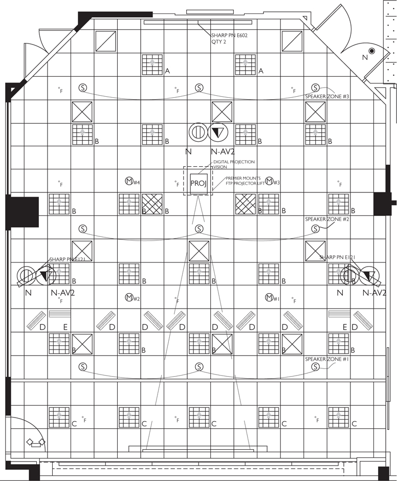
Figure 9-15 Reflected ceiling plan
The designer should check the air duct placement in relation to any projector-mounting locations or any screen-mounting locations. A misplaced air vent with a high air velocity may cause the projection screens to shake or wave.
In addition to HVAC systems, buildings incorporate fire and life safety systems, which also need to be accounted for in AV design.
Fire and Life Safety Protection
In case of fire, a fire alarm system will attempt to alert the occupants so they can be evacuated from the space. The AV professional may need to integrate the AV system with the fire alarm system to do any of the following:
• Mute the sound from an ongoing AV system to allow the alarm to be heard
• Send visual messages to a display
• Return lighting to the “on” state to allow egress
Fire suppression systems may also be installed and employed by the life safety professionals. You should be aware of the following:
• Wet systems are fire protection systems that use pressurized water.
• Dry systems do not have water constantly present in the system. Dry systems are pressurized by the fire department in the event of a fire.
• Chemical systems replace the room air with fire-inhibiting gas, such as halon, CO2, or halocarbon agents (chemical agents that contain chlorine, fluorine, or iodine, either individually or in some combination).
• Inert gas systems are designed to reduce the ambient oxygen concentration in a protected space to between 10 and 14 percent, a level that is breathable but will not support flaming combustion. These systems use inert gases such as argon and nitrogen, either as mixtures or alone.
The AV designer must coordinate their work with the mechanical engineer so that sprinkler systems are not located over projectors, which would hinder the flow of water to a fire, and projection screens, which would hide alarm indicators when they are deployed.
Fire Safety
While drilling through a firewall is sometimes unavoidable, there are ways to do so safely. For instance, always use firestop when pulling cable through a firewall. Firestop comes in many forms, such as foam, blocks, or plugs, but it all has the same basic function. It acts as an impenetrable insulator against flames.
When mounting AV equipment in the ceiling, you may find firestop in the way of your installation. Scrape off as little firestop as necessary, and make sure you replace it immediately.
Energy Management
Before we close out this chapter, we need to discuss one more element of structural and mechanical systems—energy management. You will find ANSI/InfoComm 4, Audiovisual Systems Energy Management Standard, invaluable in your design. We use the term power meter to describe the individual AV devices that you’ve installed and configured, which allows you to measure what’s in the actual space. You can think of this standard as adding a huge power meter to a room that already has AV in it.
Adhering to the Energy Management Standard is a long-term, ongoing commitment. There are seven conformance requirements in the standard.
• An energy management plan (EMP) identifies energy reduction goals.
• An energy management manager (EMM) is a role that provides leadership and management of the system.
• A wiring diagram illustrates how power to AV components is controlled and monitored and how the energy management system is connected to the AV system.
• A visual display shows end users and management the continuous power usage of the AV system.
• Use of automated devices and power-state changes ensure the AV system is energy-efficient.
• A method for continuous power measurement collects power consumption data.
• End-user operation training leads to understanding, participation, and behavior modification.
The standard centers on three big ideas.
• Data collection
• Automation
• Education and training
Each of these concepts warrants special treatment. We’ll discuss them in detail next.
Data Collection
Data collection is all about the power factor of devices and how they’re measured. If the point is to conserve energy, you have to quantify it first—how much energy is my AV system using? You add hardware to the room to gather all the data so you can analyze it.
When it comes to data collection, AV devices inside and outside of the rack collect the measurements. Measuring within the rack is easy, but devices such as projectors, displays, and digital signage add a layer of complexity.
Data collection is not just about powering the measuring devices in the rack; you have to think about remote monitoring and relay devices. Remote monitoring and relay devices are attached to an AV device in the room and allow users to monitor when the device is on, off, how much power it’s using, and so on. That information is sent to a computer, which you can then use to run reports.
NOTE How do you know if someone is in the room? Occupancy sensors are a great way to collect data about access to the space. You’ve probably been in a room where you walk in and the lights come on automatically. This is what occupancy sensors do. In terms of your AV systems, you can set them up to react when someone walks into the room. The sensor has technology in it that’s routable to the control system.
Automation
Suppose you install all your AV devices and you collect and analyze the data to find that too many devices are powered on at the same time. A critical design concept is not what should be on—it’s what should be off. This is known as off thinking.
Device power status is a major design issue. Think of a projector: It has optional power states such as on, off, disconnected, or standby. What needs to be on all the time? What can go into standby? This information is kept in the system state matrix created by the AV designer, which keeps track of the power states for individual devices in an AV system.
You should think of system design in terms of functions. Functions can include presentations, videoconferencing, and so on. The matrix allows you to keep track of what’s on, what’s off, or what’s in standby (see Figure 9-16). You can then organize all that information and integrate it into your control system so that when you switch functions, the right devices go on or off.

Figure 9-16 Sample automated setup
Well-designed automation systems are those that the end user doesn’t need to think about. Unified systems, such as room lighting, screen deployment, and audio settings, should work in harmony, delivering an experience appropriate to the use of the room.
Programming and data collection lose value if people don’t make improvements based on the information obtained about the AV system. Incorporating an energy management component into a system may lead to more responsible energy consumption. Educating end users about power consumption helps to achieve that goal.
Education and Training
End users may walk into a room, turn everything on, and use only a flip chart. Devices don’t have to be on all the time, and if you know that your system is managing energy, then it’s going to change how you think about an AV-enabled room.
Some end users don’t want to turn off the AV system because they don’t fully understand how it works. Other end users may be impatient and keep turning the system on and off because they’re not sure if it’s powered on.
The role of an energy management manager is to provide training to end users and work with the designer and integrator to understand how the system operates and how the system has been designed. Proper training ultimately enables end users to make energy-conserving decisions.
NOTE Some companies take power conservation so seriously that they turn it into a competition. To assist with that, designers can set up a display outside the room to show how many kilowatt/hours of power are used by the room each day.
Chapter Review
Mechanical systems, including the HVAC and fire suppression systems, have a significant impact on the design and layout of an AV system. The AV designer must carefully consider these elements to make sure the end users are comfortable and the equipment functions as expected.
The designer must also consider how the AV system will be integrated into the building’s structure. This includes making sure the equipment is mounted securely, accessible to the end user, and in accordance with relevant codes. Once again, the structural considerations include issues of both functionality and safety. Once you complete this chapter review, you’ll be ready to tackle the electrical infrastructure requirements of your design.
Review Questions
The following questions are based on the content covered in this chapter and are intended to help reinforce the knowledge you have assimilated. These questions are not extracted from the CTS-D exam nor are they necessarily CTS-D practice exam questions. For an official CTS-D practice exam, download the Total Tester as described in Appendix D.
1. If an amplifier draws 7 amperes (A) at 120 V of alternating current (VAC), without considering amplifier efficiency, what is the heat load it generates?
A. 2856 BTU/hr
B. 1212 BTU/hr
C. 840 BTU/hr
D. 1505 BTU/hr
2. What factors need to be considered when designing and drawing rack elevation diagrams?
A. User mobility, competence of the technician, quality of the rack material
B. Equipment manufacturer, model year of equipment, number of USB ports
C. Ergonomics, weight distribution, RF and IR reception, heat loads, signal separation
D. Amount of RJ-45 connectors used, amount of conduit used
3. According to best practices, what is the safe working load (SWL) requirement for overhead mounting of a 75 lb (34 kg) projector?
A. 500 lb (227 kg)
B. 375 lb (170 kg)
C. 300 lb (136 kg)
D. 275 lb (125 kg)
4. When installing conduit, it is important to remember that the conduit will require the following:
A. Room to expand 45 percent because of latent heating
B. Internal insulation, usually an injected polyurethane jell
C. Adequate mounting support to withstand cable pulling
D. A slip sleeve to ensure adequate air space for cable
5. What is the best place to install a 60 lb (27.22 kg) audio amplifier in a freestanding equipment rack?
A. Top of the rack.
B. Middle of the rack.
C. Bottom of the rack.
D. The location is irrelevant.
Answers
1. A. If an amplifier draws 7 amperes (A) at 120 V of alternating current (VAC), without considering amplifier efficiency, it generates 2856 BTU/hr.
2. C. When designing and drawing rack elevation diagrams, you need to consider ergonomics, weight distribution, RF and IR reception, heat loads, signal separation, and other things.
3. B. The safe working load (SWL) requirement for overhead mounting of a 75 lb (34 kg) projector is 5 * 75 = 375 lb (170 kg).
4. C. When installing conduit, it is important to remember that the conduit will require mounting support to withstand cable pulling.
5. C. The best place to install a 60 lb (27.22 kg) audio amplifier in a freestanding equipment rack is at the bottom of the rack.