
CHAPTER 16
Networking for AV
In this chapter, you will learn about
• Common networking components
• The layers of the Open Systems Interconnection model and the functions of each layer
• Common physical network connections and their capabilities
• The function and capabilities of Ethernet technologies
• The function and capabilities of Internet Protocol technologies
• The pros and cons of various Internet Protocol address assignment methods
• The differences between Transmission Control Protocol and Universal Datagram Protocol
• The characteristics of Audio Video Bridging/Time-Sensitive Networking, EtherSound, Cobranet, Dante, and HDBaseT protocols
You know about the audio and video technologies that form the core of the AV industry. More and more, though, those AV technologies rely on IT technologies to work. Modern AV systems use IT networks to support their systems in all kinds of ways. Technicians can monitor, control, and troubleshoot devices over the network. AV content is stored on the network. Audio and video signals can be distributed over network infrastructure in real time.
Realizing the potential of networked AV systems requires you to work closely with IT professionals. You need to be able to “talk the talk” to explain your needs and understand their concerns. In this chapter, you’ll get an overview of networking technologies and gain an understanding of your networking needs so you can communicate them better to your IT counterparts.
What Is a Network?
A network can consist of anything that is interconnected in a netlike manner or that is linked together to pass information. In the IT world, network is generally short for “computer network” or “data network.”
All networks consist of two basic parts: nodes and connections. Nodes are the devices that send and receive data. In the early days of networking, a node was basically a computer. Today, a node can be a computer, a mobile device, a video server, a projector, a control panel, or some other electronic system capable of sharing data.
Connections are the means by which data travels from one node to another. They can be any signal-transmission medium: radio frequency, copper cabling, light, and so on. For our purposes, passive devices, such as patch panels, also fall into this category.
The nodes use circuit switching or packet switching to transfer data across the network. A circuit-switched network sends data in a continuous stream. No other devices can use the channel while the connection is active. The public switched telephone network (PSTN) is a circuit-switched network. A dedicated connection is made between two phones. Even if no one is actually talking (in other words, no data is being sent), no one else can use that channel. Circuit-switched networks provide reliable, dedicated links. But if you have a large number of devices that need to communicate with each other, circuit-switched networks are inefficient.
By dividing data into smaller chunks, or packets, several nodes can send information on the same channel at the same time. No single device can monopolize the connection. Put another way, a circuit-switched connection is like a railroad between two cities. A train (data) can travel from one city to the other, but nothing else can use the railroad at the same time. A packet-switched connection is like a highway with many on- and off-ramps. Cars (packets) of various sizes can get on and off the highway at different points. See Figure 16-1 for help in visualizing the difference between circuit-switched and packet-switched networks.

Figure 16-1 Circuit-switched networks are like a train (top); packet-switched networks resemble a highway.
Network Components
Beyond nodes and connections, network components (Figure 16-2) can be broken down into the following:
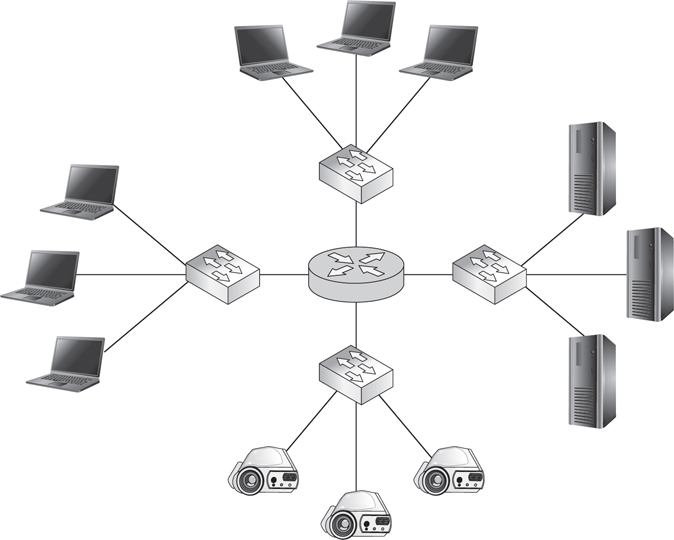
Figure 16-2 Network components: clients, servers, routers, and switches
• Clients (for example, personal computers [PCs], laptops, handhelds) and servers
• Network interface cards (NICs)
• Switches (for example, an Ethernet switch), routers (for example, an Internet Protocol [IP] router), and gateways
• Wired or wireless links
• Protocols (for example, IP or Transfer Control Protocol [TCP])
• Applications (in other words, network services)
Of these components, clients, servers, NICs, switches, routers, gateways, and links are considered hardware, while protocols and applications are considered software parts of a network. In this section, we will cover hardware components and focus on protocols later in the chapter.
Clients and Servers
Nearly all networks of significant size use servers to share resources among connected nodes. You’ve just learned that a server is a type of network hardware. To be more precise, a server isn’t really a piece of hardware. Rather, it’s a role a piece of hardware can play. If a piece of computer hardware does nothing but provide services, that computer is called a server. The term server can also refer to a program that runs on a computer alongside other programs. In a client-server network architecture, a server provides services to dependent nodes. It does resource-intensive or remotely hosted tasks that those nodes can’t perform for themselves.
Servers of larger networks usually are hosted on many separate computers. Organizations may host several servers on each computer, or they can have a dedicated computer for each service. A computer whose only task is to perform a particular service is known as a thin server. A thin server is a server that offers only one service. Typically, a thin server resides on a dedicated computer configured with only the functionality required to perform the service. This increases the resources available for the server’s dedicated task. It also minimizes the risk that a malicious intruder could exploit one of the operating system’s unused features. It’s typically a good idea to turn off any features you never use to ensure that no one else can.
Network Interface Cards
Every device that connects to the network must have a network interface card and associated media access control (MAC) address (see Figure 16-3).

Figure 16-3 A network interface card and its sample media access control address
A NIC is an interface that allows you to connect a device to a network. At one time, most devices had a separate card or adapter. Today, though, NICs are typically integrated into the device’s main circuitry.
A MAC address is the actual hardware address, or number, of your NIC device. Every device has a globally unique MAC address that identifies its connection on the network. MAC addresses use a 48-bit number expressed as six groups of two hexadecimal numbers, separated by a hyphen or colon. The first part of the number indicates the manufacturer, and the second part of the number is a serial number for the product or circuit component.
Some devices will have more than one NIC, particularly if they need to connect to multiple networks, such as both a secure classified network and an unsecure public network. It is similar in the case of devices that are wired or wireless; both connections would require a NIC.
Let’s now review the roles and differences between some common networking devices: switches, routers, gateways, and servers.
Switches, Routers, and Gateways
A network switch provides a physical connection between multiple devices. As each device is connected, the switch collects and stores its MAC address. This allows devices connected to the same switch to communicate directly with each other via Ethernet, using only MAC addresses to locate each other.
Unmanaged switches have no configuration options; you just plug in a device, and it connects. Managed switches allow the network technician to adjust port speeds, set up virtual local area networks (VLANs), configure quality of service, monitor traffic, and so on. Managed switches are more common than unmanaged switches in modern corporate and campus environments. Unmanaged switches are still used in some AV installations to allow for some basic network connections within their environment(s).
A router forwards data between devices that are not directly physically connected. They mark the border between a local area network (LAN) and a wide area network (WAN). Once traffic leaves a LAN (that is, travels beyond the switch), routers direct it until it reaches its final destination. When data arrives at a router, it examines the packet’s logical address—the IP address—to determine its final destination or next stop.
A gateway is a router that connects a private network to outside networks. All data that travels to the Internet must pass through a gateway. Routers below the gateway will forward packets destined for any device that can’t be found on the private network to the gateway. When traffic arrives from outside the private network, the gateway forwards it to the appropriate router below. Gateways also translate data from one protocol to another. See Figure 16-4 for an idea of how gateways, routers, and switches sit in a network.

Figure 16-4 A gateway, router, and switches in a network
Blended Devices
Gateways, routers, and switches do not have to be physically separate devices. Much like an audio digital signal processor (DSP) that combines the separate functions of a mixer, equalizer, compressor/limiter, and so on, networking devices often include several roles in a single box. For example, routers often include the functionality of a switch. On your home network, you probably don’t have a separate gateway, router, and switch. In fact, you may have only one router, which acts as both your gateway to the Internet and a switch directing traffic among the devices on your home network (see Figure 16-5).

Figure 16-5 A common home network router combines three functionalities.
Links
There are a lot of different physical technologies used to transport data over long distances for wide area networks: T1 lines, coaxial cable, satellite, DSL, and so on. The network connections that AV professionals have to deal with directly, though, are primarily those used within local area networks—the physical connections within a system or building. For local area network connections, the three most common physical transmission methods are as follows:
• Over copper, as voltage
• Over glass, as visible light
• Over air, as radio frequencies
Of course, it’s not as simple as it sounds. Within each transmission medium, there are several options. One copper wire network cable may have very different capabilities, limitations, and internal design than another. The same is true for fiber and wireless networks. As an AV professional, you should know which medium is best for your application and why.
Twisted-Pair Cabling
As an AV professional, you are likely to encounter only the twisted-pair cabling in networking, which is available in several categories. These categories, abbreviated Cat, are Ethernet standards under the TIA/EIA-568 standard. They are also referred to as class cables. In most LANs, you’re likely to encounter only Cat 5e and Cat 6.
Cat 5e Cabling Category 5e (Cat 5e) is the designation for 100-ohm unshielded twisted pair. It is associated with connecting hardware specified for data transmission up to 100 megabits per second (Mbps). It adds specifications for far-end crosstalk to the obsolete Cat 5 standard.
Cat 6 Cabling The conductors in Cat 6 cables have more twists per inch. They also operate at a high speed (measured in gigabits per second), which means they have high frequencies with tiny wavelengths. All of this means that Cat 6 cables are susceptible to noise. Therefore, Cat 6 cables ought to be shielded for delivery of AV signals.
Cat 6a is an augmented form of Cat 6 cables capable of 10 gigabits per second (Gbps) data transmission. These high-frequency transmissions have to account for alien crosstalk (AXT), noise of unknown origin that can’t be canceled out by active equipment like typical near and far-end crosstalk. Cat 6a cables are designed to compensate for AXT, but even so, UTP Cat 6a shouldn’t be used for cable runs of more than 180.4 ft (55 m) and should be bundled loosely to limit crosstalk. STP Cat 6a cable has better protection against electromagnetic interference (EMI) and radio frequency interference (RFI) and can, therefore, be used on longer cable runs. Cat 6a is usually used to “future proof” systems more in today’s commercial market.
Optical Fiber Cabling
Optical fiber is a glass medium used for transmitting modulated light from point A to point B. The makeup of optical fiber cabling (Figure 16-6) is simple.

Figure 16-6 Optical fiber cabling
• The core is glass medium, used to carry the light.
• Each core is surrounded by cladding, which is used to reflect the light back onto the core, keeping the signal moving down the optical fiber.
• The final layer is the coating, which protects the optical fiber from damage.
Optical fiber cabling offers high bandwidth and maintains total electrical isolation. Such characteristics allow optical fiber to maintain signal integrity in noisy environments, experiencing little signal degradation over long distances. Furthermore, optical fiber cabling is immune to EMI and RFI. Optical fiber lines are also popular for security reasons. They do not burn, withstanding aging and corrosion. Also, it is much more difficult to covertly capture data from an optical fiber line than from copper wires or radio waves. You have to physically intercept the path of the light to intercept data.
Single-Mode and Multimode Optical Fiber Cabling There are two modes, or paths of light, behind optical fiber, known as single-mode and multimode. You should think of single-mode as a straight shot; the light path is small in diameter, which makes the signal path mostly straight, with some of the signals bouncing off the walls of the glass.
Multimode is a little bit different. Some of the signal goes straight down the fiber while the rest of the signal bounces off the cladding. Because the signals are not shooting straight down the cable like they are in single-mode, the signals will take longer to reach the end of the fiber, and some light will disperse as it travels. As a result, network data can typically travel farther over single-mode than multimode.
Popular Fiber Connectors Several types of connectors are available for optical fiber cables. Currently, the straight-tip (ST), Lucent (LC), and subscriber (SC) connectors are the most popular for the AV market.
• ST connector The ST connector can be found on transmitter-receiver equipment and is similar to the Bayonet Neill-Concelman (BNC) connector. The ST connector is a bayonet connector, meaning that all you have to do is “stab and twist” to lock it into place, which keeps the optical fiber and ferrule from rotating during connection. This connector can be used on both single-mode and multimode fiber.
• LC connector The LC connector is much smaller in diameter than the ST and is used for basic wiring applications. It has low loss qualities and is known as a “push, pull” connector.
• SC connector The SC connector is larger in diameter than the LC. It is a “stab and click” connector, which means that when the connector is pushed in or pulled out, there is an audible click because of the attachment lock. This connector is useful for tight spaces.
Wireless Connections
Aside from wired connections, you’re likely to encounter wireless connections in the field, especially with clients who want to control devices or send content wirelessly over the network.
The wireless connection known as Wi-Fi is defined by the Institute of Electrical and Electronics Engineers (IEEE) 802.11 standard and has been revised several times to keep up with the growing demands for wireless communication. The speed of a Wi-Fi connection depends on the radio frequency (RF) signal strength and the revision of 802.11 with which you connect. As signal strength weakens, the speed of the connection slows. The number of users accessing the wireless devices also affects connection speed. Wi-Fi versions a, g, and n, shown in Table 16-1, are the most commonly used in the field today.
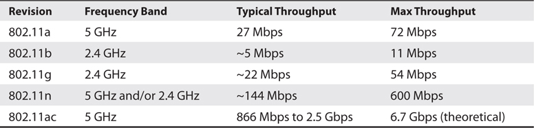
Table 16-1 Wi-Fi Versions
Wi-Fi is extremely popular, both among users and among manufacturers. It is difficult to find laptops and desktops today that do not have wireless technology incorporated into them from the factory. Computer manufacturers assume users would rather connect wirelessly than via a network cable. This might be true for the home user. For the enterprise network, however, Wi-Fi can create more problems than it solves. Before choosing Wi-Fi as a physical connection medium, you should carefully weigh its advantages and disadvantages.
Wi-Fi Advantages Wi-Fi is convenient, allows users great flexibility, and is less expensive than wired connections. It’s also become one of customer expectations. Users expect to be able to walk into a meeting room or presentation space and launch a presentation from their laptops, tablets, or mobile phones. You could try to address this requirement by providing a connection for every device imaginable. Or, you could let users connect to the presentation system using an ad hoc Wi-Fi network. In this and many other cases, Wi-Fi just seems easier. The following are some of the reasons for the popularity of Wi-Fi:
• It’s convenient. Wireless hotspots are everywhere. If your device is Wi-Fi capable, you can nearly always find a way to connect to the network.
• The convenience of Wi-Fi encourages mobility and, therefore, productivity. Workers could walk to a park, sit in a cafeteria, or ride in an airplane and still conduct business. Their work could feasibly be accomplished from anywhere.
• It requires little infrastructure. A wireless network is as simple as pulling an access point out of a box and plugging it into the wall. Most wireless access points are sold with a functional default installation. They’re as close as a network gets to “plug and play.”
• It’s scalable. If you need to add more client nodes to a wireless network, all you have to do is add more access points.
• It’s cheap. With copper or optical fiber networks, you have to buy the cables and connectors, pull them, install wall jacks, and incorporate switches and patch panels. With Wi-Fi, all you need is an access point.
Wi-Fi Disadvantages Wi-Fi has a lot of potential benefits. The list of disadvantages associated with using Wi-Fi is shorter, but the disadvantages themselves are potentially catastrophic. For some applications, you simply can’t use Wi-Fi. The following are the limitations of Wi-Fi:
• Its range is limited. Restrictions on the range of Wi-Fi devices are established by the 802.11 equipment standards and the U.S. Federal Communication Commission (FCC).
• It’s susceptible to RFI. Interference from other wireless sources can hamper Wi-Fi performance.
• Equipment selection and placement can be tricky. Proper placement, antenna selection, and signal strength are key. Building construction materials impact RF propagation. Some construction materials will dampen RF signals. Others act as reflectors, enhancing signal quality.
• It may turn out to be expensive. Though a Wi-Fi network may seem inexpensive at first, you may find yourself purchasing additional repeaters or highly directional antennas to expand the network’s range. The cost of building an extended wireless network can grow quickly.
• It’s slow. The best Wi-Fi on the market is slower than most existing wired networks. If you need to stream live high-definition video, Wi-Fi is not a dependable option.
• It’s insecure. Wi-Fi networks are far more susceptible to malicious attacks than wired networks because it’s so easy for devices to connect. For this reason, they are often severely restricted or completely prohibited in certain business, financial, and government/military facilities.
• The 2.4 GHz frequency is widely used in both commercial and consumer situations. Many commonly used devices that people use every day could be utilizing this frequency.
The OSI Model
If you’ve studied networking, you’ve probably heard of the OSI model. The Open Systems Interconnection (OSI) model provides a mental map for the transfer of data across a network. It was created in the early days of digital networking to present a common language for the technology designers and manufacturers. The OSI model can be used to describe the functions of any networking hardware or software, regardless of equipment, vendor, or application.
As the field has matured, it has become harder to fit networking technologies into the strict categories of the OSI model. Many operate at several different layers. Still, the OSI model provides a useful shorthand for discussing networking software and devices. You’ll often hear networking professionals and manufacturers talk about the layer at which a technology operates or the layer at which a problem is occurring. This section will talk you through the layers of the OSI model to help you better understand that conversation.
The OSI model is often used to describe the purpose or functionality of networking protocols, software, or devices. Knowing the OSI layer (or layers) at which a technology operates can be useful in several ways. The OSI model can do the following:
• Tell you what a technology does and when those events occur in the data transfer process. For instance, Application layer error checking occurs at the host and may be aware of the kinds of errors that really matter to the software application. Transport layer error checking has no awareness of the application; it just looks for any missing packets.
• Provide a roadmap for troubleshooting data transfer errors. The OSI model describes the signal flow of networked data. Just as you would use a signal flow diagram to troubleshoot a display system in a conference room, checking at each point in the path, you can troubleshoot a network by observing the data transfer process one layer at a time.
• Indicate which service providers are responsible for each stage of data transfer. Layers of the OSI model often represent a service provider handoff. For instance, an AV technology manager may be responsible for layer 1 and 2 devices and layers 5–7 software, while the network manager controls all layer 3 and layer 4 technology.
The OSI model uses a stack of layers to communicate or transmit a file from one computer to the next.
• Layers 1–3, known as the media layers, define hardware-oriented functions such as routing, switching, and cable specifications. These are the areas that most concern AV professionals because they’re the ones that affect us directly.
• Layers 4–7, the host layers, define the software that implements network services. Each layer contains a broad set of protocols and standards that regulate a certain portion of the data transfer process. A data transfer on any given network likely uses several different protocols at each layer to communicate. Layer 4, the transport layer, is also important to AV professionals because it’s where the transition between gear and software occurs. This layer tells the media layers which applications are sending the data. It also divides and monitors host layer data for transport.
Data is sent across a network by applications. That means when a computer sends a message, that message starts out at layer 7, the Application layer, and moves down through the OSI model until it leaves the sending device on layer 1, the physical layer.
The data travels to the receiving device on layer 1 and then moves up through the OSI model until it can be interpreted by the receiving device at layer 7, the Application layer. Let’s define each of these layers, starting where the connection starts: layer 1.
OSI Model Layers
The OSI model is broken down into seven layers (see Figure 16-7).

Figure 16-7 Open Systems Interconnection layer tasks
• Layer 1 is the physical layer. The devices need to be plugged in to work. The physical layer can be copper, optical fiber, and, yes, even RF (because it requires a signal that needs to be received). The physical layer sends and receives electrons, light, or electromagnetic flux.
• Layer 2 is the interface to the physical layer; it uses frames of information to talk back and forth. The addressing scheme is MAC addresses. One MAC address talks to another MAC address. Switches use layer 2 and send and receive frames.
• Layer 3 is packet-based. Packets “ride” inside layer 2 frames. Layer 3 adds IP addressing. Routers can send, receive, and route IP addresses.
• Layer 4 works with ports. Ports are generally associated with firewalls. These ports are virtual ports and can be found at the end of an IP address such as 192.168.1.35:80. The :80 is the port number. Port 80 is generally associated with web or Hypertext Transfer Protocol (HTTP) traffic. Routers can also route ports, but for this simplistic discussion, it helps to use firewalls to set the stage.
• Layer 5 controls (starts, stops, monitors, and keeps track of) layers 4 and 3. For example, Real Time Streaming Protocol (RTSP) keeps track of the User Datagram Protocol (UDP) layer 3 traffic. It keeps track of whether the data makes it to the far end. UDP can’t do that on its own; it needs a session protocol to do the work for it.
• Layer 6 opens up or transcodes between the session and the application. It is a kind of go-between. Data encryption and decryption are at this layer as well. An application can’t talk data directly; it needs an interpreter, and this is it.
• Layer 7 is the application layer or the layer with which the human interacts. Using the streaming example, it is Windows Media Player. The application has the controls to manipulate the output of audio and video. It takes all the layers for a player application to retrieve the stream and play it on your desktop.
No layer is skipped or bypassed. When troubleshooting, all layers need to be considered.

TIP This simple mnemonic can help you remember the names of all the layers of the OSI model, from one to seven: Please Do Not Throw Sausage Pizza Away. This stands for the following:
• Physical
• Data Link
• Network
• Transport
• Session
• Presentation
• Application
Network Types and Topologies
When people refer to networking today, they’re usually talking about a small subset of networks—packet-switched data networks. Primarily, these are ones that use Ethernet and Internet Protocol technology. Even within that narrow definition, there are different types of packet-switched networks, including the following:
• Local area networks (LANs)
• Wide area networks (WANs)
• Campus area networks (CANs)
• Metropolitan area networks (MANs)
• Personal area networks (PANs)
One of the most important characteristics of any given network is its topology. Network topology helps to determine how far data must travel to reach its destination. What path must it take? How many stops will there be along the way? Topology also bears on which network connections carry the most traffic and helps AV professionals figure out how to send AV signals over a network. Network topologies fall into two basic categories: physical topologies and logical topologies.
The physical topology is the “way it is wired” or how it is physically connected together. Physical topology maps the physical placement of each network device and the cable installation path. Where will the devices and cables actually be? Physical topology is constrained by the actual space the network equipment occupies.
The logical topology depicts electrical routing and control of data. Even though you have physically connected everything, do you really want to send all the data to all devices? Most likely not. You want to find a solution that is most efficient and moves data quickly. The logical topology is how you manage the data routes. Physical and logical topologies are like a team, and changing one player can affect what happens in the field.
Logical topology (Figure 16-8) maps the flow of data within a network. Which network segments and devices must data pass through to get from its source to its destination? Logical topology is not defined or constrained by physical topology. Two networks with the same physical topologies could have completely different logical topologies, and vice versa.

Figure 16-8 Sample logical network topology
So, what can you learn from looking at a network’s topology? Topology reveals how many devices data has to pass through before it gets to its destination—in other words, how many hops are between each device. Many real-time AV protocols have a limited number of allowable hops, usually fewer than ten. When you look at hops, you also see which devices the data has to pass through. A lot of real-time AV protocols can’t travel over WANs; if the topology indicates that data has to pass through a router to get from one device to another, you know you have a problem.
Topology also shows which devices and connections have to handle the most data. This helps network engineers figure out which parts of their network need the most capacity.
Finally, topology can show where a network’s weak spots are. When you look at a LAN topology, you should always look for single points of failure. A single point of failure is any one device whose failure will cause the entire system to fail. A single point of failure could be any device that a number of other devices depend on. For example, it could be a network switch that lots of other devices use to communicate, or it could be an audio digital signal processor (DSP that handles inputs and outputs from lots of other devices). Whenever possible, you want to make single point-of-failure devices redundant, so if one fails, another device is ready and waiting to take its place. As a best practice, no more than 20 devices should be affected by any one single point of failure.

NOTE Connections, as well as devices, can be points of failure. It doesn’t matter if a device is working perfectly if the cable that connects the device to the network is damaged beyond working.
Local Area Networks
Data sent across a network must be sent to an address. That address will be either physical or logical. Networks are classified according to whether nodes use physical or logical addresses to communicate.
Local area networks use physical addresses to communicate. As mentioned earlier in this chapter, the LAN’s physical address is the MAC address, hard-coded into each node. LANs are usually privately owned and operated. They are fast and high capacity. Most real-time AV network protocols—for example, Audio Video Bridging/Time-Sensitive Networking, EtherSound, and CobraNet (discussed further in this chapter)—are designed for LAN speeds/capacity.
LANs require devices to be directly, physically connected (see Figure 16-9). This requirement effectively limits their geographical size. You can send an electrical signal only so far before it degrades beyond use.
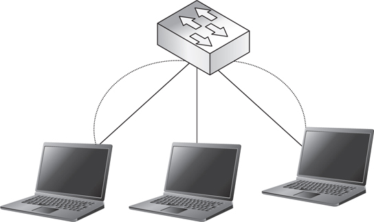
Figure 16-9 Sample local area network
Stated simply, data travels across a LAN as follows:
1. Data sent across a LAN is addressed to the MAC address of one of the devices on the LAN.
2. A switch receives the packet and examines the MAC address to which it is addressed.
3. The switch forwards the packet to the appropriate device.
Local Area Network Topologies
Devices can be connected on a LAN in several ways.
• In a star topology, all nodes connect to a central point, such as a router, switch, or hub. Star networks are hierarchical. Each node has access to the other nodes through the central point. If any one node fails, information still flows. The central device is a single point of failure; if it fails, communication stops.
• Star topologies are often extended to include more than one layer of hierarchy. This is known as an extended star topology. If any device fails, access to the devices below is cut off, but the rest of the network continues to work. The central device remains a single point of failure; if it fails, communication stops.
• In a mesh topology, each node connects to every other node. Mesh topologies provide fast communication and excellent redundancy, ensuring that the failure of no one device can bring down the whole network. Providing physical connections between every device is really expensive, though. Fully meshed networks are rare.
• In a partial mesh topology, each node connects to several other nodes, but not all. Partial mesh topologies provide good redundancy, ensuring that several devices must fail at the same time before communications cease.
Ethernet
Ethernet is the standard for how data is sent across LANs from one connected device to another.
Ethernet has become the de facto standard for LANs. The IEEE 802.3 Ethernet standards define a data frame format, network design requirements, and physical transport requirements for Ethernet networks. When IP data is sent across a LAN, it is encapsulated inside an Ethernet frame. The Ethernet frame (Figure 16-10) is generated by the device’s NIC. The frame has a header and a footer that surround the packet, which ensures that the packet will arrive intact at its destination.

Figure 16-10 An Ethernet frame generated by a device’s network interface card
The following types of Ethernet are in use today (Figure 16-11):

Figure 16-11 Ethernet types in use today
• 10 Mbps Ethernet
• 100 Mbps Ethernet
• 1 Gbps Ethernet
• 10 Gbps Ethernet
• 40/100 Gbps Ethernet
Each of these types of Ethernet has its own capabilities, intended applications, and physical requirements. You’re only likely to encounter 10 Mbps Ethernet on legacy systems. The 100 Mbps Ethernet technologies are backward compatible with 10 Mbps, though. That means you will often see 100 Mbps referred to as 10/100 Mbps Ethernet technologies in the field. The 40/100 Gbps Ethernet is a fairly young technology and primarily intended for use as a network backbone—to connect networking devices such as routers and switches to each other, or for use by Internet service providers, rather than to connect individual client nodes to a switch. As a result, you may not work with much 40/100 Gbps Ethernet in the field.
The type of Ethernet your device sends out depends on the capability of its NIC. Not every device can handle sending and receiving data at a rate of 1 Gbps or more. Remember, the overall speed of your Ethernet connection is no faster than the slowest link in its path.
Ethernet technologies are interoperable. A frame can originate on a 100 Mbps Ethernet connection and later travel over a 1 Gbps or 10 Gbps Ethernet backbone. As a general rule, you need a faster technology to aggregate multiple slower links. If your end nodes communicate with their switches by using 100 Mbps Ethernet, the next layer of the network hierarchy may need to be 1 Gbps Ethernet, and so forth. As devices become capable of faster network speeds, even faster backbones will be required.
The IEEE released its first Ethernet standard, 802.3, in 1985. The original Ethernet standard was for 10 Mbps data transportation. “Classic Ethernet,” as 10 Mbps Ethernet is sometimes called, was originally designed to operate in half-duplex because it predates switching technology. However, today you can find 10Base-T implementations that use switches to achieve full-duplex communication.
You may still see classic Ethernet in use in the field. It’s sometimes used to connect end nodes such as computers and printers to switches or, in older networks, hubs. The network access equipment (for example, switches, routers, hubs, and so on) and heavily used shared resources such as servers are then connected to each other using a faster backbone.
10 Mbps Ethernet 10 Mbps Ethernet (Table 16-2) was originally designed to be transported on coaxial cable. The Ethernet standards that relied on coax cable are now considered obsolete. Like faster forms of Ethernet, classic Ethernet now runs mostly on twisted-pair Cat cable. On a campus network, optical fiber cable can also be used to span the distance between buildings.

Table 16-2 10 Mbps Ethernet Characteristics
Fast Ethernet IEEE approved the standard for 100 Mbps Ethernet in 1995. The 100 Mbps Ethernet is also known as Fast Ethernet (see Figure 16-12). Fast Ethernet can operate in either full-duplex mode, using switches, or half-duplex, using hubs. Fast Ethernet is commonly used both to connect end nodes to switches and hubs and to connect network access equipment and servers to each other. In larger or more traffic-heavy networks, though, Fast Ethernet is not fast enough for the network backbone.

Figure 16-12 100 Mbps or Fast Ethernet
Fast Ethernet was originally designed to be backward compatible with classic Ethernet.
It uses the same frame structure and can operate over the same optical fiber and twisted-pair cables, though coaxial isn’t an option. The idea was to allow networks to upgrade to Fast Ethernet without having to replace their entire cable infrastructure and all their existing devices.
However, using Cat 3 cables for Fast Ethernet is pretty limiting. Fast Ethernet over Cat 3 can operate only in half-duplex mode. Over Cat 5, Fast Ethernet can operate in half- or full-duplex. Also, when Fast Ethernet came out, existing NICs and hubs couldn’t handle the faster data rates over Cat 3 cabling without the help of expensive processing electronics. They could handle Fast Ethernet over higher-performing Cat 5 cables, though. Because many companies found upgrading their cables cheaper than purchasing new equipment, Fast Ethernet led to the widespread adoption of Cat 5 cable infrastructures. See Table 16-3 for further characteristics.

Table 16-3 100 Mbps Ethernet Characteristics
Gigabit Ethernet IEEE approved the standard for 1 Gbps Ethernet over fiber, 802.3z, in 1998. 1 Gbps Ethernet over copper, 802.3ab, followed in 1999. 1 Gbps Ethernet is also known as Gigabit Ethernet (Figure 16-13).

Figure 16-13 1 Gbps Ethernet
Some end nodes have NICs capable of Gigabit Ethernet transportation, and some don’t. You’ll see it used to connect end nodes to switches when required and possible, but more often, Gigabit Ethernet is deployed as a network backbone. That means it’s used to connect network access equipment, such as switches and routers, and servers with Gigabit Ethernet NICs. Gigabit Ethernet is practically always implemented in full-duplex mode. Though it’s technically possible to run Gigabit Ethernet in half-duplex, many network equipment manufacturers don’t even make gigabit hubs—only switches.
Like Fast Ethernet, Gigabit Ethernet was designed for backward compatibility. It can run over the same multimode fiber and Cat 5 cabling as Fast Ethernet. However, unlike 10Base-T or 100Base-TX, Gigabit Ethernet over Cat 5 uses all four pairs in the cable to transmit and receive data (see Table 16-4). Gigabit Ethernet standards also allow single-mode fiber, enabling even longer distances. Gigabit Ethernet also uses four-conductor shielded cables, terminated with a DB-9 or RJ45 connector, for specific purposes, such as connecting blade servers to switches.

Table 16-4 1 Gbps Ethernet Characteristics
10 Gigabit Ethernet IEEE approved the standard for 10 Gbps Ethernet over fiber, 802.3ae, in 2002. The 10 Gbps Ethernet over copper, 802.3an, followed in 2006. The 10 Gigabit Ethernet operates only in full-duplex. It’s primarily intended for use as a backbone to connect switches to each other. The 10 Gigabit Ethernet dramatically increased the range of Ethernet connections, enabling Internet service providers (ISPs) to use Ethernet as a WAN technology for the first time. The 10 Gigabit Ethernet can be used to do the following:
• Connect multiple switches within a LAN
• Interconnect clusters of servers
• Connect an organization directly to an ISP site
• Connect switches within an ISP network
Originally, 10 Gigabit Ethernet was designed to run on fiber over long distances. Eventually, standards for running 10 Gigabit Ethernet over copper emerged. First came short-reach, four-conductor cabling used primarily for connections within data closets—switch to switch or server to switch. Eventually, though, 10 Gigabit Ethernet also adapted the simple, ubiquitous, and inexpensive Cat cable. As in other applications, the range of 10 Gigabit Ethernet over Cat cable is significantly shorter than the range over fiber. As such, 10 Gigabit Ethernet over Cat cable isn’t really intended for use as a long-range network backbone. Instead, its purpose is to provide links between server clusters in a data center—a communication pathway for supercomputers. See Table 16-5 for physical medium characteristics.

Table 16-5 10 Gigabit Ethernet Characteristics
40/100 Gbps Ethernet IEEE approved a single standard for 40 Gbps and 100 Gbps Ethernet over fiber, 802.3ba, in 2010. Like 10 Gigabit Ethernet, 40/100 Gigabit Ethernet operates only in full-duplex. Again, the main purpose of the new standard is to aggregate slower connections. Recall that connections generally need to be aggregated by an even faster connection. As the use of 10 Gigabit Ethernet grows, 40/100 Gigabit Ethernet networks will be required to aggregate multiple 10 Gigabit nodes. In general, 40 Gigabit Ethernet is intended for uses in data center applications. The 100 Gigabit Ethernet is intended for aggregating 10 Gigabit Ethernet switches and providing ISP and network backbones.
As of this writing, the only available physical media for 40/100 Gbps Ethernet are fiber and four-conductor, balanced, shielded twisted pair (see Table 16-6). If history is any indication, though, Cat cabling standards won’t be too far behind.

Table 16-6 40/100 Gbps Ethernet Characteristics
Isolating Local Area Network Devices
You don’t always want all the devices on a LAN to be able to communicate directly via Ethernet. Sometimes, you want to ensure that certain devices have access only to one another and that outside devices can’t easily talk to them.
This may be for security reasons. Some servers or devices host sensitive information that other devices shouldn’t be able to access.
You may also want to isolate certain groups of devices to limit the traffic they receive (see Figure 16-14). All networked devices send out occasional administrative messages, called broadcast messages, that go to every other device on the LAN. Sometimes, you want to limit the amount of broadcast traffic a group of devices receives.

Figure 16-14 Isolating LAN devices
The need to limit traffic is particularly relevant to certain networked audio and video implementations. AV traffic is time sensitive. For some AV protocols, broadcast traffic from non-AV devices on the LAN is enough to cause serious quality problems. You need a way to put these devices in a cone of silence, shutting out traffic from outside the AV system.
You can simply get dedicated switches for your AV system, isolating it on its own physical LAN. This is a simple and popular solution to the problem, and sometimes it’s the only feasible option.
Virtual Local Area Networks
Potentially, though, an isolated physical LAN lets existing IT infrastructure go to waste. There is a way to isolate devices on a LAN from other devices connected to the network, shutting out their broadcast traffic. You can place the devices in a virtual local area network. VLANs can be configured on managed switches—the MAC addresses of the devices are associated with the VLANs they belong to. When the switch forwards data from a device in a VLAN, it adds the VLAN identifier to the Ethernet frame.
VLANs aren’t related to a network’s physical layout. Devices in a VLAN can be connected to different switches in completely different physical locations. As long as those switches are in the same LAN (in other words, they don’t have to go through a router to contact each other), the devices can be placed in a VLAN together.
Because VLANs are virtual, you can even place a device on more than one VLAN. Devices in a VLAN can send each other Ethernet traffic directly. They also receive each other’s broadcast traffic. They don’t receive any broadcast traffic from the other devices on the LAN.
They also can’t communicate with devices outside the VLAN via Ethernet. Traffic in and out of the VLAN has to go all the way through the router.
Virtual Local Area Network Uses Because the communication among devices on a VLAN is typically switched rather than routed, it’s very efficient. Devices in separate physical locations that need to communicate mostly with each other should be on a VLAN. This makes their traffic more efficient while keeping it out of the way of other data.
Digital signage is a great VLAN application example. If you have a campuswide deployment of signs that all draw their content from a centrally located digital signage player, those devices probably belong on a VLAN. You’re unlikely to need to access other systems such as file servers or mail servers from your signage player or displays. Still, if you do want to send information from a database or directory to your signs, they can still be accessed via the router.
Some AV data link protocols don’t play well with others. CobraNet, for instance, is not designed to share network segments with other types of data. Placing all CobraNet devices on a single VLAN, however, isolates them on a broadcast domain. This leverages the existing physical infrastructure while putting the CobraNet traffic in virtual solitary confinement. (See “Data Link Layer Protocols” in this chapter for more information about AV data link protocols.)
Requesting Virtual Local Area Networks If you determine that a system should be segregated on a VLAN, for either its own good or that of the network, you’ll need to provide the network manager with the following information:
• What VLAN you want to create and why (for example, “I want to create an IPTV VLAN so that the network isn’t flooded with streaming video traffic”)
• Which devices should be included in the VLAN
• Whether any routing between the VLAN and other network locations is required or allowed
This information should all be documented as part of your system device inventory.
Wide Area Networks
A wide area network is a network that connects one or more LANs together (Figure 16-15). WANs use logical addresses to communicate. The form a logical address takes depends on the type of WAN. However, for the purposes of this course—and most modern WANs—the logical address is an Internet Protocol address. An IP address is assigned to a device, either manually or automatically. It may be permanently assigned, or it may change over time. It may or may not be unique.

Figure 16-15 Sample wide area network
The nodes on a WAN are routers. If a LAN is connected to outside networks via a WAN, a router sits at the top of its network hierarchy. Any data that needs to travel to a device outside the LAN gets forwarded to the router. The router strips the packet of identifying LAN information, such as the MAC address of the originating device, before forwarding the packet to its intended IP address. This protects the devices on the LAN.
A WAN can be any size. It may connect two LANs within the same building. It may span the entire globe, like the world’s largest WAN, the Internet. Unlike LAN connections, long-distance WAN connections are rarely privately owned. Usually, WAN connections are leased from ISPs. The speed and capacity of a WAN connection are often tied directly to how much you pay for it.
WAN communications travel farther than LAN communications. As a result, they’re slower—maybe only by a fraction of a second. In live audio and video transmission, however, second fragments matter. As a result, many networked AV protocols can’t travel over WANs.
Wide Area Network Topologies
WAN topologies can also be placed into a few common categories.
• Hub and spoke In a hub-and-spoke WAN, each LAN connects to a central location. For example, several branch offices may connect to a corporate headquarters. Like a star LAN, a hub-and-spoke WAN may have several layers of hierarchy, with several hubs connecting to several spokes.
• Common carrier In a common carrier WAN, each LAN site runs a spoke to an ISP backbone.
• Mesh In a fully meshed WAN, every LAN connects to every other LAN. This provides excellent redundancy.
One of the major advantages of networking is the ability to share resources. When examining a WAN topology, try to identify the best place to locate shared resources. In a hub-and-spoke topology, shared resources should be located at the hub. In a common carrier topology, the enterprise may choose to lease space at the ISP and host shared resources there, or it may choose to pay for a lot of bandwidth to and from one of its sites and locate resources there. In a mesh WAN topology, resource location is generally accomplished by building a network map, including the data throughput of all connections, and locating resources “in the middle.”
Shared AV resources, such as streaming servers or multipoint control units (MCUs), will ideally be stored in the same physical location as shared IT resources. In some cases, however, you may not have access to IT server closets for security reasons.
Virtual Private Networks
Almost any large or physically dispersed organization will require some way to hold managed communication between its LANs. Services that are particularly necessary for AV applications, such as quality of service (QoS), low latency, managed routing, and multicast transmission, are impossible over the open Internet. Customers and service providers also commonly need a secure means of accessing systems remotely for monitoring, troubleshooting, and control purposes. Virtual private networks (VPNs) provide a way.
A VPN uses the Internet to create a tunnel between two or more LANs. VPNs are used to create virtual WANs and for remote monitoring, troubleshooting, and control. VPNs are typically controlled and configured by the enterprise network administrator. Each host requires the proper software, access rights, and password to log into the client network.
VPNs are often built into security devices such as firewalls. Organizations using VPNs at scale may require dedicated VPN devices. Using a VPN increases required bandwidth overhead as well, because an encryption and tunneling wrapper must be added to each packet. This additional overhead may not be significant in terms of bandwidth requirements, but it can increase the Ethernet frame size to the point where packets must be fragmented before they can be sent across the network. Packet fragmentation can be disastrous for the quality of streamed video or conferences. Always be sure your frame size is set low enough to account for VPN overhead.
There are different types of VPNs, each with their own characteristics.
Layer 2 Tunneling Protocol
Layer 2 Tunneling Protocol has the following characteristics:
• Client devices must have client software installed.
• It can transport both IP and non-IP data.
• It monitors data integrity, authenticates data origin, and protects against data “capture and replay.”
• It can introduce significant latency.
• It is not commonly used in newer systems.
Internet Protocol Security
Internet Protocol Security (IPSec) has the following characteristics:
• Client devices must have client software installed.
• It is an IP-based protocol, and it provides security for any IP transport protocol (TCP, UDP, Internet Control Message Protocol [ICMP], and so on).
• It can authenticate and encrypt, or just authenticate, based on need.
• It assigns remote devices an internal address upon connection, making them effectively on the LAN.
• Remote clients have access to the same devices and resources they would on-premise.
• Client software may manage clients by requiring them to have antivirus software or a host-based firewall.
• It is commonly used for site-to-site connections.
Secure Sockets Layer
Secure Sockets Layer (SSL) has the following characteristics:
• No client software is needed—the client accesses the VPN via a web browser.
• It requires a dedicated SSL VPN server.
• It’s an IP-based protocol (TCP only).
• It does not require an internal address.
• It acts as a proxy allowing only authorized users to access only approved resources; access can be configured on an individual user basis.
• It’s common for mobile user–to-site connections.
Network Layer Protocols
Once AV data joins other data on a routed WAN, Network layer protocols take care of logical addressing, routing, and, in some cases, prioritizing data as it moves from device to device. The rise of the Internet has made the Internet Protocol the de facto Network layer protocol for enterprise applications and networked AV systems.
Internet Protocol
IP is the postal service of the Internet that sets rules for how to package and address mail. If you don’t include the right information in the address, it won’t be delivered. If you don’t package it correctly, it will get damaged in transit. Just like the postal service, IP assumes responsibility for making sure your data arrives at its destination, although, just like with the postal service, some messages do get “lost in transit.” The IP covers several crucial functions that make WAN networking possible. IP defines the following:
• Addressing Rules for how each system is identified, what the addresses look like, and who is allowed to use which addresses
• Packaging What information must be included with each data packet
• Fragmenting How big each packet can be and how overly large packets will be divided
• Routing What path packets will take from their source to their destination
Internet Protocol Addresses
An IP address is the logical address that allows devices to locate each other anywhere in the world, no matter where they are physically. An IP address requires three distinct components.
• Network identifier bits These bits identify the network. They help the IP packet find its destination LAN. The network bits are always the first digits in an IP address.
• Host identifier bits These bits identify a specific node. They help the IP packet find its actual destination device. The host bits are always the last bits or least significant bits in a network address.
• Subnet mask These bits tell you which bits in the IP address are the network bits and which bits are the host bits. The subnet mask also reveals the size of the network. The subnet mask is a separate address that must be included with the IP address.
IP addresses can look very different depending on which version of the Internet Protocol was used to create them. There are two versions of IP currently in use: version 4 (IPv4) and version 6 (IPv6).
IP functionality differs depending on which version is implemented, as shown in Table 16-7.

Table 16-7 Internet Protocol Functionalities by Version
Internet Protocol Version 4 Addressing
IPv4 addressing was originally defined in 1980, in the IETF standard RFC 760. IPv4 is being slowly phased out in favor of IPv6. The fact remains that while the world will eventually need to transfer to IPv6, this hasn’t happened yet and appears to be a long way from happening. IPv4 is still the most prevalent Internet addressing scheme, so you need to be familiar with its structure.
An IPv4 address consists of four, 8-bit groups, or bytes. Those bytes are usually expressed as decimal numbers separated by dots—dot-decimal notation. Hence, an IP address looks like this:
192.168.1.25
Remember, each of those decimal numbers actually represents 8 bits. That same address, written in binary, looks like this:
11000000 10101000 00000001 00011001
The entire range of IPv4 addresses includes every possibility from all 0s to all 1s. In dot decimal notation, that range is expressed as follows:
0.0.0.0 to 255.255.255.255
In total, there are almost 4.3 billion possible IPv4 addresses. Several of these addresses are reserved for specific purposes, but that’s still a lot of possible addresses. Unfortunately, 4.3 billion addresses aren’t enough. Think about it—there are 7 billion people in the world. About 2.4 billion of those have Internet access. Now consider how many different Internet-connected devices you use in a day. Three? Four? More? This is why IPv4 is being phased out—it’s not big enough for today’s Internet.
Internet Protocol Version 4 Subnet Masks Looking at an IPv4 address (Figure 16-16), how can you tell which bits identify the network and which bits identify the host? To interpret any IPv4 address, you need a separate 32-bit number called a netmask, or subnet mask.

Figure 16-16 Internet Protocol version 4 subnet mask
A subnet mask is a binary number whose bits correspond to IP addresses on a network. Bits equal to 1 in a subnet mask indicate that the corresponding bits in the IP address identify the network. Bits equal to 0 in a subnet mask indicate that the corresponding bits in the IP address identify the host. IP addresses with the same network identifier bits as identified by the subnet mask are on the same subnetsubnet.
For example, subnet mask 255.255.255.0 indicates that the first three octets of any corresponding IP addresses are the network address and the last octet is the host address.
In its structure, an IPv4 netmask looks a lot like an IPv4 address. It consists of four bytes, expressed in dot-decimal notation. A subnet mask could be written something like this:
225.255.255.0
When you write the netmask out in binary, though, you can see the difference between an IPv4 netmask and address. A netmask never alternates 1s and 0s. The first part of the netmask will be all 1s. The second part of the netmask will be all 0s. Written in binary, the previous subnet mask would be as follows:
11111111 11111111 11111111 00000000
Used in combination with an IP address, the netmask identifies which bits in the IP address are the network identifier bits and which are the host bits. All the devices on the same network have the same network identifier bits in their IP addresses. Only the host bits will differ.
IPv4 Subnet Notation In IPv4, there are two ways to express a subnet mask.
• You can write it out as its own full, dot decimal number.
• Or you can attach it to the end of an IP address using Classless Inter-Domain Routing (CIDR) notation. CIDR notation is just a slash, followed by a number. The number tells you how many of the address bits are network bits (any remaining bits are host bits).
CIDR notation is basically just a shorthand. 255.244.192.0 and /18 are two different ways of writing the same subnet mask. In binary, both are equal to 11111111 11111111 11000000 00000000.
Internet Protocol Version 6 Addressing
An IPv6 address consists of 16 bytes—that’s four times as long as an IPv4 address. Because IPv6 addresses are so long, they are usually written in eight, four-character hexadecimal “words,” separated by a colon. Since each hexadecimal character represents 4 bits, each word represents 16 bits. In IPv6 (see Figure 16-17), here’s what the characters represent:
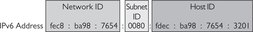
Figure 16-17 Internet Protocol version 6 address
• The first three hexadecimal words are the network identifier bits.
• The next hexadecimal word identifies the subnet.
• The final four hexadecimal words are the host identifier bits.
Note that the host identifier portion of an IPv6 address is long enough to include a MAC address. IPv6 can actually use a device’s MAC address as the host identifier. Some IPv6 implementations even do this automatically. Because a MAC address uniquely identifies a device, using the MAC address as the host identifier should ensure that no two devices ever have the same IPv6 address.
The IPv6 subnet mask isn’t really there to tell you which bits identify the network and which bits identify the host. It’s there to allow you to subdivide the network. You always have 48 bits to identify the network and 64 bits to identify the host. That means that under IPv6, there are more than 281 trillion different possible network addresses. Each network address can have more than 18 quintillion unique hosts. That’s an unimaginably large number. We’re not going to run out of IPv6 addresses any time soon.
IPv6 Subnet Masks IPv6 still has netmasks, but the netmask “masks” only a certain part of the address. An IPv6 subnet mask (Figure 16-18) can be written out in eight full hexadecimal words, but the first three words of the netmask will always be all 1s, and the last four will always be all 0s. As a result, many implementations of IPv6 allow you to enter the subnet mask as a single four-character hexadecimal word. The subnet mask seen here could be written as simply c000.

Figure 16-18 Internet Protocol version 6 subnet mask
You can also express an IPv6 subnet mask using CIDR notation. The CIDR suffix for an IPv6 address will almost always be between /48 and /64.
Types of IP Addresses
In both IPv4 and IPv6, certain portions of the address range are set aside for specific purposes. As a result, there are several different types of IP addresses that all look pretty much the same. Experienced network professionals can tell what types of addresses they’re dealing with by looking at them. If you can recognize an IP address’s type, you’ll be able to distinguish which addresses can be used to identify AV devices and which cannot.
The Internet Assigned Number Authority (IANA) is in charge of giving out IP addresses or reserving them for specific purposes. IANA maintains three categories of addresses: global, local, and reserved. Most of the reserved addresses are not routed on the public Internet. Table 16-8 shows the more important reserved IP addresses and their purposes.

Table 16-8 Reserved IPv4 Addresses
Global Addresses Most LANs connect to the Internet at some point. To access the Internet, you need a global IP address. That is, you need a public address that any other Internet-connected device can find. Global addresses go by many names in the networking community, including globally routable addresses, public addresses, or publicly routed addresses. IANA assigns global addresses upon request.
Any IP address that’s not in one of the local or reserved address ranges can be a global address. Basically, global addresses are the “other” category. If an IP address isn’t a local or reserved address, it’s a global address.
Local Addresses Not all devices need to access the Internet directly. Many devices need to communicate only with other devices on their LAN. This is particularly true for networked audio implementations. IANA reserves three IPv4 address ranges and one IPv6 address range for local networking.
The addresses in these ranges are private. Devices with private IP addresses can’t access the Internet or communicate with devices on other networks directly.
There are three IPv4 private address ranges (see Table 16-9). The range you use depends on the size of your network. These ranges were defined before the development of CIDR, so the ranges correspond to the old address classes.

Table 16-9 Internet Protocol Version 4 Private Address Ranges
If your network is so big that it would have required a Class A address under the old classful system, your IPv4 private address range will start with 10.x.x.x. If your network would have required a Class B address, your private address range will start with 172.16 to 31.x.x. Small networks use private addresses that start with 192.168.x.x.
The major advantage of private network addresses is that they are reusable. Global addresses have to be completely unique; no two organizations can use the same IP address to access the Internet. Otherwise, whenever data was sent to or from that address, there would be no way to know which network was intended. Since private addresses can’t access the Internet, though, several different organizations can use the same private address range. Devices on different networks can have the same private IP address, because those devices will never try to talk to each other or to any of the same devices. As long as no devices on the same LAN have the same IP address, there’s no confusion.
The obvious disadvantage of private addresses is that they can communicate only with devices on the same network. They can’t be routed to the Internet. Initially, this made the networking community reluctant to use them. In 1994, the IETF introduced a new service that solved this problem: network address translation (NAT).
NAT is any method of altering IP address information in IP packet headers as the packet traverses a routing device. NAT is a TCP/IP service first defined in the IETF standard RFC 1631. The purpose of NAT is to resolve private IP addresses to public IP addresses, and vice versa, so that devices with private addresses can send data across the Internet. NAT is typically implemented as part of a firewall strategy. NAT operates at the Internet layer of the TCP/IP protocol stack and the Network layer of the OSI model.
NAT is typically implemented on devices at the edges of the LAN (for example, routers, web servers, or firewalls). When a device with a private IP address sends data to the public Internet, the data has to stop at one of these edge devices along the way. Before forwarding the packet, the edge device strips the private source IP address and replaces it with a global IP address. The edge device keeps track of all the data it forwards this way. Then, if any packet receives a reply from the Internet, the edge device can translate the global destination address back into the private IP address that should receive the data.
NAT has several advantages. First, it allows private IP addresses a way to access the Internet, limiting the demand for global addresses. Second, it limits the number of devices exposed to the Internet, enhancing security. Third, if you ever switch ISPs, you receive a new set of global IP addresses. Using NAT, you only have to configure the addresses of the edge devices. The private addresses don’t have to change.
Broadcast Address In addition to private addresses, there are other types of addresses that can’t or don’t send data outside the LAN. One type of IPv4 address, when used as a destination address, will send the datagram to every device on the same network: the broadcast address (Figure 16-19).
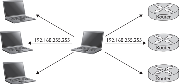
Figure 16-19 Sample broadcast address
Broadcast addresses are used as the destination IP address when one node wants to send an announcement to all network members. Broadcast messages are simplex—there’s no mechanism for the other nodes to reply to the node that sent the message. An IPv4 broadcast address is any IPv4 address with all 1s in the host bits. When data is sent to that address, it goes to every device with the same network bits.
Loopback Address Both IPv4 and IPv6 have a special address type for testing devices: the loopback address. Sending data to a loopback address is like calling yourself. Data addressed to a loopback address is returned to the sending device. The loopback address is also known as the localhost, or simply home.
The loopback address is used for diagnostics and testing. It allows a technician to verify that the device he’s using is receiving local network data. Essentially, it allows you to ping yourself. IPv4 and IPv6 each reserve specific addresses for loopback.
• IPv4 reserves 127.0.0.0 to 127.255.255.255 as loopback addresses. Any address in this range can be used, but most network devices automatically use 127.0.0.1 as their loopback address.
• IPv6 uses the address ::1 as the loopback address.
Subnetting
Subnetting divides a network into smaller networks (see Figure 16-20). Each smaller network is called a subnet. Subnets are created when the subnet mask is extended. Instead of stopping at the end of an octet, the 1s in the subnet mask spill over to the next octet.

Figure 16-20 Subnetting a network
For each bit the subnet mask is extended, the network is divided in half.
• If the subnet mask is extended one bit, you end up with two subnets.
• If the subnet mask is extended two bits, each subnet is divided again. You end up with four subnets.
• As you divide the network, each subnet will be slightly less than half the size of the original network.
It’s important for you to know about subnets because they affect how your devices communicate. For devices to communicate directly by Ethernet or belong to the same VLAN, they have to be in the same subnet.
Why do organizations subnet their networks? The main reason is to increase network efficiency. A subnet has fewer addresses than a full class network, so address resolution is faster. Fewer devices also mean less broadcast traffic—devices on a subnet receive broadcast messages only from other devices on the same subnet, not from the whole undivided network.
In certain cases, subnetting can also improve network security. For example, say you have a full class C address, with 254 possible global addresses, but only your router and your web server actually need direct Internet connections. You have 252 unused addresses lying around that someone could use to register their own device to your network. If you extend your subnet mask to /30, however, there are suddenly only two possible public addresses. Assign one to your web server and the other to your router, and there’s no room for anyone else.
How Subnetting Works
A 192.168.1.x network with a subnet address of 255.255.255.0 has 256 possible unique addresses. You can think of this as 256 “slots” into which you can insert a device. The first slot, 192.168.1.0, is taken. This is the network address, and most switches won’t allow you to assign it to a device. The last slot, 192.168.1.255, is taken as well. This is the broadcast address—it can’t be assigned to a single device either. Any packets sent to this address go to every device on the network.
The remaining 254 slots can each contain a single device. All these devices can communicate with each other directly via Ethernet. When one of these devices sends broadcast traffic, it goes to all 254 devices.
You can subnet this network by changing the subnet mask to 255.255.255.128, or 11111111.11111111.11111111.10000000. Doing so splits the network in half at the center. Slots 0 to 127 are now in one network, and slots 128 to 255 are in the other. Now you have four unusable slots.
• Slot 0 is still unavailable. It’s the network address of the first network.
• Slot 127 is now taken as well. It’s the broadcast address of the first network.
• Slot 128 is taken too. It’s now the network address of the second network.
• Slot 255 is still unavailable. It’s the broadcast address of the second network.
The devices in each network can communicate with each other only directly via Ethernet. If the device in slot 1 wants to send a message to the device in slot 126, it can do so through the switch. If it wants to send a message to the device in slot 129, it must go through the router. Similarly, if the device in slot 1 sends a lot of broadcast traffic, only the devices in slots 1 to 126 receive it. The devices in slots 129 to 254 are in a different broadcast domain.
You can continue splitting the network into 4ths, 8ths, and so on, by extending the subnet mask. Each time you split the network, you halve the number of devices that can belong to each subnet, minus two slots for the newly created broadcast and network addresses.
IP Address Assignment
Every device that communicates across a TCP/IP network must have an IP address. Broadly speaking, there are two ways for a device to get an IP address. A device can be manually assigned a permanent address (static addressing), or it can be automatically loaned an address on an as-needed basis (dynamic addressing). Both ways play important roles in introducing AV systems to a network.
Although it requires thoughtful management, dynamic addressing requires less work in general. Instead of manually configuring an IP address for every connected device, nodes obtain addresses on their own. Because all the addressing is handled by computers, dynamic addressing avoids the risk of human error. Users won’t fail to connect because someone typed an incorrect IP address.
Because it’s easier to maintain, especially on larger networks, expect to see dynamic addressing used whenever possible. That said, not all devices support or should use dynamic addressing. Dynamic addresses, by nature, change. Therefore, if, for instance, you need a control system to always be able to locate a device by its IP address, you should assign that device a static address.
Assigning static addresses isn’t hard. Each network operating system has its own tool for doing so. In addition, the individual device may also have a software interface that allows you to hard-code its static address. You need at least three pieces of information to manually assign an IP address: the device’s MAC address, the IP address, and the subnet mask.
You might also need to know the address of the default gateway—that is, the address of the router that the device uses to access other networks. If the network uses the Domain Name System (DNS), you also need the device’s assigned domain name and DNS server. (See the section “Dynamic Name System” for more information.)
Where do you get all this information? Likely from the network manager or IT department. Whenever you add an AV system to a TCP/IP network, you’ll work closely with your IT counterparts to discover and document your system’s requirements. During that process, you’ll let the IT department know which AV devices need IP addresses.
The IT department may give you a subnet mask and address range to use, or they may tell you specifically what address to use for each device. In either case, make sure both you and the IT department keep track of which IP addresses and MAC addresses are permanently associated with AV devices.
Static and Dynamic Addresses
Every device that communicates across a TCP/IP network must have an IP address. Broadly speaking, there are two ways for a device to get an IP address.
• The device can be manually assigned a permanent address. This is known as static addressing.
• The device can be automatically loaned an address on an as-needed basis. This is known as dynamic addressing.
Though it does require thoughtful management, dynamic addressing is less work in general. Instead of having to manually configure an IP address on every connected device, nodes obtain addresses on their own. Because all the addressing is handled by computers, dynamic addressing avoids the risk of human error. You won’t fail to connect because of an incorrectly entered IP address.
Because it’s easier to maintain, especially on larger networks, you can expect to see dynamic addressing used whenever possible. Not all devices support or should use dynamic addressing, though. Dynamic addresses can change. If, for instance, you need a control system to be able to locate a device by its IP address, you should assign the device a static address.
Static Addresses Assigning a static address to a device isn’t hard. Each network operating system has its own tool for manually assigning addresses. The individual device may also have a software interface that allows you to hard-code its static address. You’ll need at least three pieces of information to manually assign an IP address.
• The device’s MAC address
• The IP address
• The subnet mask
You might also need to know the address of the default gateway—the address of the router the device uses to access other networks. If your network uses DNS, you’ll also need the device’s assigned domain name and DNS server.
Where do you get all this information? You’ll need to work with the network manager or IT department. Whenever you add an AV system to a TCP/IP network, you’ll work closely with your IT counterparts to discover and document the system’s requirements. During that process, you’ll let the IT department know what devices need static IP addresses. Be sure to specify that all the devices in the system should be on the same subnet. The IT department may give you a subnet mask and address range to use, or they may tell you specifically which address to use for each device. In either case, make sure both you and the IT department keep track of which IP addresses and MAC addresses are permanently associated.
You can document static IP address assignments using a table or spreadsheet like the one shown in Table 16-10. The AV team provides the information in the first four columns; the IT team provides the last three. You may want to include a lot more information in this spreadsheet, but these basics will help you and the IT department maintain the system and the network.

Table 16-10 Sample Static Internet Protocol Address List
How Static Addressing Works Static addresses have to be manually entered into the device. The network manager has to document and manually keep track of which devices have static addresses and what addresses they have been assigned. If any two devices have the same addresses, most likely neither will work because of the conflict. As a result, keeping track of static addresses can be painful for network managers.
Dynamic Host Configuration Protocol
Dynamic Host Configuration Protocol (DHCP) is an IP addressing scheme that allows network administrators to automate address assignment. When a device connects to the network and the device has the “obtain IP address automatically” option activated, the DHCP service or server will take the MAC address of the device and assign an IP address to the MAC address. The pool of available IP addresses is based on the subnet size and the number of addresses that have been allocated already. Addresses are leased for a preset amount of time. After the lease time has expired, the address may be assigned to another device. The network administrator sets the amount of the lease time.
This is how an unknown device can connect to the Internet on a new network with no manual configuration. When you log onto the free Wi-Fi at a coffee shop or airport, your device is given an IP address on that network via DHCP. For DHCP to work, there must be a DHCP server on the network. One server can assign addresses to devices on multiple network segments—multiple subnets. That server keeps track of the following:
• The network’s address range
• Which addresses are currently available
• Which addresses are currently in use by which devices
• The remaining lease time on each address
To use DHCP, a device must have the “obtain IP address automatically” option activated. When such a device starts up or tries to connect to the network for the first time, it will automatically request an IP address from the DHCP server. Provided the server has an address available, it will take the MAC address of the device and assign an IP address to that MAC address. Then, it will start the countdown on the address’s lease time.
Dynamic Host Configuration Protocol Address Pool The size of the available address pool depends on three factors.
• Size of the subnet the device is connecting to
• Number of addresses already in use
• Number of addresses reserved for another purpose
Once a device obtains an IP address from a DHCP server, it may or may not keep that address for a long time. The DHCP lease time is set by the network administrator. It could be three hours, three days, or thirty days—whatever the administrator thinks is appropriate. If the device renews its lease within the lease period, it gets to keep its address. If it doesn’t—if it’s moved to another network or is otherwise idle when its lease runs out—it will lose that address. The address goes back into the DHCP server’s pool of available addresses. The next time that device connects to the network, it may or may not get the same address.
Dynamic Host Configuration Protocol Advantages DHCP is simple to manage. If you move a device from one network or subnet to another, DHCP takes care of resetting the device’s address and network settings for you. It ensures no two devices get the same address, which relieves potential conflicts. It allows more devices to connect to the network as the pool of addresses is continually updated and allocated. For example, a coffee shop may have thousands of customers using their Wi-Fi in the course of a week. Does that mean they need thousands of host addresses? Not with DHCP. With DHCP, you only need enough host addresses to cover the devices that are using the network at the same time.
The disadvantage to DHCP is that you never know what your IP address will be from connection to connection. If you need to reach a certain device by IP address, you must have a high level of confidence that the number will be there all the time, and DHCP may not give you that confidence.
How Dynamic Host Configuration Protocol Works DHCP reserves a pool of slots to be leased for a given amount of time. The lease time is based on how many devices need addresses and how often those devices enter and leave the network. For example, at an airport, users log on and off the network at fairly quick intervals. A DHCP server’s lease time there may be set to 15 minutes so that unused addresses are quickly surrendered back into the pool. At an office, however, the lease time may be much longer—10 or 24 hours.
Any device that requests an address from the DHCP server is assigned one from the pool. Once all the slots in the pool are occupied, no new devices can join until a lease expires. The areas above and below the DHCP pool may still be used for static addressing. Often network administrators block out several pools within a network for printers, servers, networking components, and so on.
Reserve Dynamic Host Configuration Protocol Reserve DHCP (Figure 16-21) is a method of establishing static addresses on a DHCP server. Using reserve DHCP, a block of statically configured addresses can be set aside for devices whose IP addresses must always remain the same. The remaining addresses in the subnet will be assigned dynamically. The total pool of dynamic addresses is reduced by the number of reserved addresses.

Figure 16-21 Illustrating reserve Dynamic Host Configuration Protocol
To reserve addresses for AV devices, you need to list the MAC address of each device that requires a static address. The manually assigned static IP address and MAC address are entered into a table in the DHCP server. When the device connects to the network and reveals its MAC address, the DHCP server will see that the IP address is reserved for the device and enable it. The IP address cannot be given to any other device or MAC address.
Essentially, you’re using your DHCP server to keep track of your manually configured settings. This allows you to keep all your address assignments—static and dynamic—in a single database. That way, you can avoid any risk of duplicate address allocation. If you manually configure the devices themselves instead of reserving their addresses through the DHCP server, the server doesn’t know those addresses aren’t available and may assign them to another device.
TIP If you have a DHCP server, it’s best to use a hybrid approach rather than manually assigning an IP address to each AV device.
How Reserve Dynamic Host Configuration Protocol Works Reserved DHCP addresses are often preferred over static addresses because they are far easier to administer. A network administrator takes the device’s MAC address and associates it with an IP address from within the DHCP pool on the DHCP server. This reserves the IP address and prevents it from being leased by another device. The device can then be set to obtain its address from the DHCP server. Every time it requests an address, it will be directed to the same slot. No static addressing at the individual device needs to occur.
NOTE If the device is replaced, the MAC address needs to be reported and reconfigured on the DHCP server so that the new device can assume the old IP address.
Automatic Private Internet Protocol Addressing Sometimes, a device on a DHCP-enabled network can fail to get an address from a DHCP server. This can happen for a number of reasons.
• DHCP is not configured properly on the client.
• The DHCP server has exhausted the IP address pool.
• The DHCP server is improperly configured.
• The DHCP server has mechanically failed.
• DHCP services are bound to MAC addresses, and the client MAC address is not defined on the server.
If this happens, will the device be unable to use the network? Not necessarily. It won’t be able to access other network segments or the Internet, but it may still be able to communicate with other devices on its own network segment using Automatic Private IP Addressing (APIPA).
APIPA is a form of link-local addressing defined in the IETF standard RFC 3927. APIPA automatically assigns locally routable addresses from the reserved network 169.254.0.0/16 to devices that do not have or cannot obtain an IP address. This allows devices to communicate with other devices on the same LAN. APIPA operates at the Network layer of the OSI model and the Internet layer of the TCP/IP protocol stack.
For APIPA to work, it must be enabled on the client device. If the device doesn’t have an IP address and can’t get one from the DHCP server, APIPA enables the device to assign itself an IPv4 address. This address must come from the reserved APIPA address range, 169.254.0.1 to 169.254.255.254. The addresses in the APIPA range are considered part of the private IP address scheme. That means they cannot be routed outside of the local network. Once a device has an APIPA address, it can communicate with other devices as long as they:
• Are on the same subnet
• Also have APIPA enabled
When a device has an IP address but can’t connect to the Internet, network troubleshooters often look for link-local addresses like APIPA addresses.
Domain Name System
Devices on a network need to have unique identifiers. At the Data Link layer, devices are uniquely identified by their MAC addresses. At the Network layer, devices are uniquely identified by their IP addresses. But what if you want to find the same device over and over? Sending a message to that device’s IP address won’t necessarily work. The device’s IP address may have changed; the lease on its old address could have run out, or the device may have been moved to another network. Even if the device has a static address, are you really going to remember that address? Committing long strings of characters to memory is easy for computers—they have hard drives for that. People need an easier way.
Naming services allow people to identify network resources by a name instead of a number. From the human perspective, names are a lot easier to understand than numeric, or alphanumeric, addresses.
DNS is the most widely used system for name-to-address resolution. If you use the Internet, you use DNS. The web addresses you type into a browser aren’t actually addresses. They’re DNS names. Every system that connects to the Internet must support DNS resolution.
A DNS is a hierarchical, distributed database that maps names to data such as IP addresses. A DNS server keeps track of all the equipment on the network and matches the equipment names so they can easily be located on the network or integrated into control and monitoring systems.
The goal of the DNS is to translate, or resolve, a name into a specific IP address. DNS relies on universal resolvability to work: Every name in a DNS must be unique so that information sent to a domain name arrives only at its intended destination.
DNS uses DNS servers to resolve names to addresses. The server contains a database of names and associated IP addresses. These servers are arranged in a hierarchy. Each server knows the names of the resources beneath them in the hierarchy and the name of the server directly above them in the hierarchy. If a server receives a request to resolve a name for a device beneath it, it can resolve that request itself. If it receives a request to resolve the name of an unfamiliar device, it will forward that request to the server above it. This is why DNS is known as a distributed database. No one device has to keep track of all the names and IP addresses on the Internet. That information is distributed across all the DNS servers on the network.
Internal Organizational DNS You don’t need your own DNS server to resolve the names of web addresses on the Internet. You can do that through your ISP’s DNS server. However, many organizations use DNS internally to manage the names and addresses of devices on their private networks. In this case, you will need your own DNS server. A DNS server is a software program. It runs on a computer. In fact, it can run on the same computer as your DHCP server. Usually, you will have a master DNS server and at least one secondary DNS server that runs a copy of the database stored on the master. This provides a backup in case the master ever fails. If an organization is really dispersed, you may want to locate a secondary DNS server at each physical site. This keeps DNS traffic off the WAN.
Using a service called dynamic DNS (DDNS), DNS can work hand in hand with DHCP. DDNS links and synchronizes the DHCP and DNS servers. Whenever a device’s address changes, DDNS automatically updates the DNS server with the new address. When DHCP servers and DNS are working together, you may never need to know the IP address of a device—only its name. This makes managing the network simpler. The IP address does not need to be static. The entire addressing scheme could change without affecting the communication between devices.
A domain name has three main parts, from left to right (see Figure 16-22).

Figure 16-22 Sample addressing scheme
• A computer name or alias
• The domain itself
• The top-level domain (TLD)
A domain may be further divided into subdomains. This system helps prevent any two devices from being assigned the same name. Any number of computers may be called “www,” as long as they belong to different domains.
A DNS is built of hierarchical text files called resource records (RRs). RRs can be difficult to maintain or change; doing so is usually the purview of a dedicated DNS administrator or service provider. RRs contain far more information than the domain name and associated IP address. For instance, they contain data class information that can be used as a load balancer; the DNS may round-robin web requests within a certain class. There are many different types of RRs. Service (SRV) records are particularly important. SRV records are used to identify which devices host specific services, such as Active Directory or the Session Initiation Protocol (SIP) server.
IP addresses may be dynamically assigned to domain names via DHCP. With dynamic DNS, you may never need to know the IP address of a device, only its name. Since the IP address does not need to be static, this makes managing the network simpler. The entire addressing scheme could change without affecting the communication between devices.
DNS Adoption The advantages of using DNS address assignment for a networked system seem obvious.
• Devices can be identified by easily remembered names.
• Dynamic DHCP makes control and remote monitoring systems much easier to maintain.
• DNS includes load balancing functionality.
The fact is, many AV devices still don’t natively or fully support DNS address assignment. If you want to connect a device without native DNS support to a network with a DNS addressing scheme, the SRV records pointing to that device will have to be updated manually. DNS servers exist in a hierarchy, so if the device’s SRV record isn’t automatically published to every DNS server above it in the hierarchy, each server will have to be manually updated. If your device supports DHCP but not DNS, you’re usually better off reserving a pool of DHCP addresses for your devices by MAC address than manually configuring the SRV records.
Since IPv6 is adopted alongside (and eventually replaces) IPv4, DNS should become more commonplace on AV devices. IPv6 addresses are simply too long and susceptible to errors to enter manually; IPv6 will likely force the widespread adoption of DNS.
Transport Layer Protocols
Layer 3, the Network layer, is responsible for assigning IP addresses to network devices and identifying paths from one network to another. The actual end-to-end transportation of data, however, is handled by layer 4, the Transport layer.
In the lower layers of the OSI model, each layer carries the layer above it. Physical layer technologies (layer 1) carry Ethernet frames (layer 2), which carry IP packets (layer 3). This is called encapsulation.
However, Transport layer protocols are not encapsulated inside IP packets. Instead, Transport layer protocols fragment IP packets into smaller chunks that fall within the maximum transmission unit (MTU) of the network connection. This process is known as segmentation. The transport protocol is responsible for segmenting data for transmission and reassembling it at its destination.
A transport protocol may be connection oriented or connectionless. Connection-oriented transport protocols are bi-directional. The source device waits for acknowledgment from the destination before sending data. It checks to see whether data has arrived before sending more. Connection-oriented transport includes things such as error checking and flow control to make sure data arrives as it should.
Connectionless communication is one-way. The source device sends data, which the destination device may or may not receive. Connectionless protocols are less reliable than connection-oriented protocols, but they are also faster. Many media-oriented applications, including practically all real-time protocols, use connectionless transport protocols.
In the TCP/IP protocol stack, Transmission Control Protocol is the most commonly used connection-oriented transport protocol; Universal Datagram Protocol is the most commonly used connectionless protocol. The two methods differ in speed and reliability. You must be able to identify—and in many cases decide—what kind of transport protocol your AV devices will use to send information over the network.
Transmission Control Protocol Transport
Transmission Control Protocol is a connection-oriented, reliable Transport layer protocol. TCP transport uses two-way communication to provide guaranteed delivery of information to a remote host (see Figure 16-23). It is connection-oriented, meaning it creates and verifies a connection with the remote host before sending it any data. It is reliable because it tracks each packet and ensures that it arrives intact. TCP is the most common transport protocol for sending data across the Internet.

Figure 16-23 Transmission Control Protocol data transfer between two networked devices
TCP data transfer involves the following steps:
1. TCP communication starts with a “handshake” that establishes that the remote host is there and negotiates the terms of the connection; in other words, how many packets can be sent at once. The number of packets that can be sent together are referred to as a sliding window.
2. The origin device sends one sliding window at a time to the destination device.
3. The destination device acknowledges receipt of each sliding window, prompting the origin device to send the next one.
4. The sliding window can’t move past a packet that hasn’t been received and acknowledged. If any packets are damaged or lost in transmission, they will be re-sent before any new packets are sent.
Figure 16-24 shows the TCP stack. Because TCP is reliable and connection-oriented, it’s used for most Internet services, including HTTP, FTP, and Simple Mail Transfer Protocol (SMTP).

Figure 16-24 Transmission Control Protocol stack
Universal Datagram Protocol Transport
TCP, the most common IP transport protocol, is reliable, but it can also be slow. UDP transport is designed to transmit information when timing is more important than missing packets.
Universal Datagram Protocol is a connectionless, unacknowledged Transport layer protocol. UDP begins sending data without attempting to verify the origin device’s connection to the destination device and continues sending data packets without waiting for any acknowledgment of receipt (see Figure 16-25).

Figure 16-25 Universal Datagram Protocol communication between two devices
In UDP transport, it does the following:
• The origin computer does not attempt a “handshake” with the destination computer. It simply starts sending information.
• Packets are not tracked, and their delivery is not guaranteed. There is no sliding window.
UDP lacks TCP’s inherent reliability. That doesn’t mean all data transmitted using UDP is unreliable, though. Systems using UDP may manage reliability at a higher level of the OSI model, such as the Application layer.
Figure 16-26 shows the UDP stack. UDP is used for streaming audio and video. When packets are lost in transport, UDP transport just skips over missing bits, inserting a split second of silence or a scrambled image instead of coming to a full stop and waiting for the packets to be re-sent.

Figure 16-26 Universal Datagram Protocol stack
UDP may also be used to exchange small pieces of information. In some cases, such as retrieving a DNS name, a TCP “handshake” takes more bits than the actual exchange of data. In such instances, it’s more efficient to use the “connectionless” UDP transport.
Transmission Control Protocol vs. Universal Datagram Protocol
In TCP transport, the participants acknowledge one another, and there’s a back-and-forth exchange to ensure that information is communicated clearly. With UDP transport, it is not clear how much of the message will get through to the intended recipient.
More specifically:
• TCP transport is used when the guaranteed delivery and accuracy or quality of the data being sent are most important, such as when sending control signals.
• UDP transport is used when speed and continuity are most important, such as during any real-time communications.
Be aware, however, that many enterprises have policies against UDP traffic. UDP streams can be used in malicious attacks such as denial-of-service attacks, which swamp network equipment with useless requests, or Trojan horse viruses. If you want to use UDP transport for streaming media, be prepared to defend its necessity.
Ports
A port number indicates to the server what you want the data to do. Many are permanently assigned by the IANA to standardized, well-known services.
System ports, 0 to 1023, are assigned to standards-track protocols. These are also known as well-known ports. User ports, 1024 to 49151, are assigned by IANA upon request from an application developer. Dynamic ports, 49152 to 65535, cannot be assigned or reserved. Applications can use any dynamic port that is available on the local host. Table 16-11 shows TCP and UDP ports assigned to several different protocols.

Table 16-11 Protocol Port Assignments
Data Link Layer Protocols
As the industry advances, you will need to grow familiar with important layer 2 protocols such as Audio Video Bridging/Time-Sensitive Networking, EtherSound, Cobranet, Dante, or HDBaseT. They are all transported over standard structured cable. Most use Ethernet frames to package and transport data. As AV streaming protocols, they require a minimum data throughput of 100 Mbps.
Many AV link layer protocols require specialized infrastructure (routers, switches, and so on) specifically designed to support them.
Why Professional AV Needs Its Own Protocols
Leaving aside the massive amounts of infrastructure—billions of dollars’ worth of dedicated servers and connections—that make consumer services such as YouTube and Netflix possible, professional AV really is special. Internet streaming media services can offer good-quality streams of recorded audio and video to multiple users. This AV data has been compressed and encoded before delivery to users—a time- and CPU-consuming process. Even so, users expect to have to wait for their streaming media. Many videos load for a short time before they will play, and the streaming experience is often interrupted by “buffering” while more data downloads. If there isn’t enough bandwidth to deliver the full stream, the service provider may switch to a lower-quality stream or simply pause delivery for a bit.
These little inconveniences aren’t permissible in many professional AV applications. Professional AV applications are often live. You’re transporting audio and video that’s being transduced into data in real time. Think about the difference in quality you’ve seen between recorded and live video feeds you see on the Internet. The live feeds are typically much lower resolution, and they often refresh only a few times per second, or even less. That level of quality isn’t acceptable in a professional AV enterprise application.
When you’re streaming audio and video in real time, you can’t stop to buffer. If there isn’t enough bandwidth to deliver all the data, the data gets lost or delayed. If the data is lost, the result is unintelligible, clipped audio and blocky video. Some amount of delay or latency may be permissible. It depends on your application. In general, the more interactive the AV application, the less latency it can tolerate. A lecture that’s being streamed live to a spillover room can tolerate several seconds of latency. A live, two-way conversation cannot. A networked audio system in a stadium can’t tolerate much latency either—you don’t want the announcers’ commentary to lag behind the action on the field.
Transporting real-time audio and video to multiple destinations on a LAN typically requires special Data Link protocols designed for that purpose. These protocols make sure that the AV data arrives in sequence, with minimal latency. They also have special network design requirements associated with them: permissible topologies, minimum Ethernet standard requirements, and so on. They may require special hardware or software. They may require AV devices to be isolated in a VLAN. Implementation can be challenging. In the end, though, these special AV protocols allow you to leverage existing IT infrastructure to transport professional-quality AV signals to hundreds of endpoints at once.
Audio Video Bridging/Time-Sensitive Networking
There are many protocols designed to deliver real-time audio or video over LANs. Most are proprietary; that is, they were developed by a private company, which owns the right to their use. They may license the technology to other manufacturers, but they will profit from any implementation of the protocol. There is at least one open, standards-based protocol for delivering real-time audio and video over Ethernet: Audio Video Bridging (AVB), which has recently been renamed to Time-Sensitive Networking (TSN).
AVB/TSN is a suite of standards in development by the same organization that maintains the Ethernet standards, IEEE. Right now, the complete AVB/TSN standard is still in development by an IEEE 802.1 task force. However, the AVB/TSN suite includes several standards that have already been completed and ratified. As a result, AVB/TSN is already in use in the field. The following AVB/TSN standards have already been ratified:
• IEEE 802.1AS Timing and Synchronization in Bridged Local Area Networks Among other functions, 802.1AS allows devices with different sampling rates to send AV media on the same system. It also ensures audio and video streams stay in sync with each other.
• IEEE 802.1Qat Stream Reservation Protocol This reserves a portion of network bandwidth for the AV stream. Reservation is different from traditional QoS priority. It actually closes off a portion of the network bandwidth so that only AVB traffic can use it. The percentage of the network that can be reserved is adjustable.
• IEEE 802.1Qav Forwarding and Queuing for Time-Sensitive Streams This guarantees that AVB traffic will arrive on time, without too much latency or too many lost packets.
Other AVB standards are still in the ratification process. This includes 802.1 BA AVB Systems, the standard that will define the defaults and profiles that manufacturers need to implement to make their LAN equipment AVB/TSN-compatible. Like Ethernet, AVB/TSN is an open standard. Any manufacturer can choose to implement and support AVB on their devices.
The aim of the complete AVB/TSN standard suite is plug-and-play networked AV. AVB/TSN-enabled devices should detect one another automatically. AVB/TSN-enabled switches should recognize AVB/TSN traffic and prioritize it appropriately. AVB/TSN networks are supposed to configure themselves, without any need for you to segregate AV equipment on a separate physical network. The catch is that every device in the system must be AVB/TSN compliant. That includes the network switches; they must be “media-aware” switches, capable of detecting and prioritizing AVB/TSN traffic. Such switches are known as AVB/TSN bridges.
Audio Video Bridging/Time-Sensitive Networking Topologies
AVB/TSN can use any LAN topology—bus, ring, star, mesh, and so on—but AVB/TSN data has a maximum of seven “hops.” In other words, it can pass through no more than seven devices on its journey from source to destination, not counting the source and destination. Within those restrictions, latency in AVB/TSN networks is limited to 2 milliseconds.
AVB/TSN is designed to operate on a converged network—that is, alongside other data on the same LAN. It’s able to do this because of its reservation and forwarding and queuing protocols. With AVB/TSN, AV data automatically occupies the top two levels of QoS on the switch. Everything else, including Voice over IP (VoIP), Internet traffic, and so on, is assigned a lower priority level. AVB/TSN allows AV traffic to travel on the same network as other traffic because it enables the AV data to cut in line at the switch and reserve up to 75 percent of network connections for itself.
TIP Not every organization will be comfortable prioritizing AV data in this manner. Even if your customers are comfortable with this, they may be unwilling to replace their LAN infrastructure with AVB/TSN-compliant devices. In that case, you’re left with two options: a physically separate AVB/TSN LAN or a proprietary Data Link layer solution.
EtherSound
The first networked audio solution to make it to market was EtherSound. EtherSound was developed by Digigram and made available to the public in 2001. EtherSound is a combination of hardware, control software, and data transportation protocol technologies (see Figure 16-27 for sample topologies). EtherSound transports real-time audio and control, but it does not transport video.

Figure 16-27 EtherSound topologies
The audio sources have to either be EtherSound-enabled or be connected to an EtherSound-enabled device. Digigram licenses EtherSound technology to many different audio equipment manufacturers. It uses standard networking devices, though any standard switch or hub can forward EtherSound data. EtherSound data is packaged inside Ethernet Frames. It is a Data Link layer technology and can’t be routed outside the LAN.
Ethernet Requirements and Capabilities
There are two main versions of EtherSound: ES-100 and ES-Giga. As you might guess, ES-100 requires 100 Mbps Ethernet or better. ES-Giga requires Gigabit Ethernet or better. ES-100 supports up to 64 channels of bi-directional 24-bit, 48 kilohertz (kHz) audio and control. ES-Giga supports up to 256 channels of 24-bit, 48 kHz audio and control, plus 100 Mbps of standard Ethernet for non-EtherSound control signals. As usual, the maximum number of channels an EtherSound connection can support depends on the quality of the audio stream. If the audio is encoded at a lower bit depth or sampling rate, you’ll be able to send more channels over a single connection.
Unlike AVB/TSN, EtherSound requires dedicated bandwidth. Typically, that means the EtherSound network should be on its own physically separate LAN. You can use existing network infrastructure, though, and place all EtherSound devices within a VLAN. In that case, you will have to reserve bandwidth for the EtherSound VLAN on all the network switches.
EtherSound Latency
You can predict the amount of latency in an EtherSound network based on its topology. There’s 104 microseconds (µs) of latency native to the network because of the time it takes to buffer data into Ethernet frames. Each node the data passes through adds about 1.4 µs of latency. By counting the number of nodes between the source and destination nodes on an EtherSound network, you can calculate the amount of latency. Note that the latency will be slightly different at each daisy-chained endpoint.
CobraNet
CobraNet is a competitor to EtherSound developed by Cirrus Logic. In many ways, it’s similar. CobraNet is a combination of hardware, control software, and data transportation protocol technologies. It transports real-time audio and control, but it does not transport video. The audio sources have to either be CobraNet-enabled or be connected to a CobraNet-enabled device. Cirrus Logic licenses CobraNet technology to many different audio equipment manufacturers. Like EtherSound, it uses standard networking devices—any standard switch or hub can forward CobraNet data. CobraNet data is packaged inside Ethernet Frames. It is a Data Link layer technology and can’t be routed outside the LAN.
Ethernet Requirements and Capabilities
CobraNet is designed to be transported over 100 Mbps Ethernet or better. As long as the network is fully switched, CobraNet data doesn’t require dedicated bandwidth. It can coexist on a LAN with other data. That said, it may still be a good idea to isolate CobraNet devices in a VLAN, shutting out broadcast traffic. You can also run CobraNet on a network that uses hubs instead of switches, but design guidelines are much stricter. In that case, a separate LAN may be required.
Over Fast Ethernet (100baseT), a single CobraNet connection supports up to 64 channels of bi-directional 20-bit, 48 kHz audio and control over a single connection. It carries fewer channels if the bit rate is higher and more if the bit rate is lower. Gigabit Ethernet and faster can, of course, support even more channels.
CobraNet Topologies and Latency
Like AVB/TSN, CobraNet can run over any Ethernet topology. Just as with AVB/TSN, the number of nodes does not affect network latency. Latency is the same at each end point. According to Cirrus Logic, 5.33 ms of latency is introduced by the process of buffering AV data into Ethernet frames. CobraNet standards allow another 3.8 ms of latency. This could come from several different sources. Additional conversion (for example, digital to analog, sampling rate, and so on) may add another millisecond. Each switch the data passes through will also add some latency. How much depends on the overall volume of network traffic and the QoS priority of the CobraNet data. The number of hops allowed in a CobraNet network is therefore determined by the allowable latency. In general, six hops is the maximum, but more time-sensitive applications can tolerate even fewer hops.
Dante
Not all AV data transportation protocols are limited to the LAN. Dante is a proprietary Network layer audio transportation protocol developed by Audinate. AVB/TSN, EtherSound, and CobraNet all package data as payloads directly inside Ethernet frames. Dante packages audio data as a payload inside an IP packet. That means Dante traffic is fully routable—a router can send it from one LAN to another or from inside a VLAN to outside a VLAN. Like EtherSound or CobraNet, Dante transports audio and control and no video. Dante encompasses hardware, control software, and the transportation protocol itself. The audio sources have to either be Dante-enabled or be connected to a Dante-enabled device. You can turn a Windows or Apple computer into a Dante-enabled device using Audinate’s proprietary software, Dante Virtual Sound Card. Any standard switch or router can forward Dante data.
Ethernet Requirements and Capabilities
Dante requires a switched Ethernet network of 100 Mbps or better, with at least a Gigabit Ethernet backbone. Dante doesn’t require dedicated bandwidth. It uses the VoIP DiffServ category to prioritize audio and control data over other data. Therefore, it can coexist on a LAN with other data. Over Fast Ethernet, a single Dante connection can carry 48 channels of bi-directional 24-bit, 48 kHz audio. Over Gigabit Ethernet, a single Dante connection can carry 512 channels of bi-directional 24-bit, 48 kHz audio. As always, the actual limit on the number of channels depends on the quality of the audio stream. High-quality equals fewer channels, and vice versa.
Dante Topologies and Latency
Like AVB/TSN and CobraNet, Dante can run over any Ethernet topology. The latency of the Dante network is set by the system administrator and managed by the Dante control software. You set the latency based on the size of the network. For live sound, Audinate recommends setting a latency of no more than 1 ms. If the Dante packet arrives at its destination device before the set latency period is up, the device will actually delay it a little. This ensures that all Dante nodes remain in sync.
However, unlike AVB/TSN and CobraNet, Dante devices don’t need to have the same latency at each node. Using the Dante control software, you can configure some network paths to allow more latency (for example, the path to a recording device), thereby freeing up more bandwidth for time-critical network paths (for example, the paths to your loudspeakers). Be forewarned: This flexibility has a price. Lower latency requires more bandwidth. Lowering your latency will limit the number of possible channels. Dante networks have a maximum of 10 hops.
Q-Sys
Q-Sys is a proprietary networked audio transportation protocol developed by QSC. Like Dante, Q-Sys is a Network layer audio transportation protocol. It too packages audio data inside IP packets, meaning it can be routed from one LAN to another. Like EtherSound, CobraNet, and Dante, Q-Sys transports audio and control signals and no video. Q-Sys encompasses hardware, control software, and the transportation protocol itself. A Q-Sys network requires several proprietary QSC audio products to work, including a Q-Sys Core central processor and server, I/O frames that convert analog audio to and from Q-Sys packets, and network design software. Any standard switch or router can forward Q-Sys data.
Ethernet Requirements and Capabilities
Q-Sys requires end-to-end Gigabit Ethernet or better. Q-Sys doesn’t require dedicated bandwidth or physically separate networks, but like Dante and AVB/TSN, they do require QoS. Q-Sys requires that its clock data be in the network’s highest QoS class and its audio streams be in the high-middle “assured forwarding” class. Q-Sys control data and management data can be in the “best effort” class. Depending on the Q-Sys Core used, a single Q-Sys connection may carry up to 512 channels of bidirectional audio.
Q-Sys Topologies and Latency
Q-Sys employs centralized processing—the Q-Sys Core performs the audio processing for the network. As a result, Q-Sys networks typically employ a star or extended star logical topology, with the Core at the center of the network (see Figure 16-28). As in a Dante network, the amount of latency in a Q-Sys network is configurable, from 2.5 ms up to 4.5 ms in a larger network. Q-Sys networks have a maximum of seven hops.

Figure 16-28 Q-Sys topology
HDBaseT
HDBaseT is an alternative approach to networked AV. Unlike AVB/TSN, EtherSound, CobraNet, Dante, and Q-Sys, it is not carried in Ethernet frames or IP packets. It cannot pass through conventional network switches and routers. IT and HDBaseT networks use the same Cat 5e or better cables and RJ-45 connectors, but that’s where the similarities end. An HDBaseT network is a dedicated network, built with special components. It doesn’t interface with the IT network except as a system source. It bears mentioning here as an alternative to Ethernet-based AV networks.
HDBaseT was developed by the HDBaseT Alliance, a group of manufacturers. It was originally intended for use in the consumer market but has made inroads into the professional AV market as well, particularly in digital signage and surveillance cameras. All devices in the HDBaseT signal chain must be capable of transmitting and/or receiving HDBaseT.
HDBaseT Capabilities
HDBaseT carries uncompressed 2K/4K video, as well as audio and control signals. It is also capable of carrying up to 100 watts of power—you might not even need to plug HDBaseT displays and other end nodes into the wall. HDBaseT can also carry 100 Mbps Ethernet. This capability allows HDBaseT devices to access content on connected computers.
Chapter Review
Before you can send any signals across a network, especially AV signals, you have to understand how data travels through the network. In this chapter, you learned about network components, types, and topologies, as well as how different protocols play out in the design and operation of AV/IT networks. You’re now ready to take on streaming design, which is the focus of Chapter 17.
Review Questions
The following questions are based on the content covered in this chapter and are intended to help reinforce the knowledge you have assimilated. These questions are not extracted from the CTS-D exam nor are they necessarily CTS-D practice exam questions. For an official CTS-D practice exam, download the Total Tester as described in Appendix D.
1. A __________ uses unique, hard-coded physical addresses, known as media access control (MAC) addresses, to send data between nodes.
A. Personal area network (PAN)
B. Local area network (LAN)
C. Global area network (GAN)
D. Wide area network (WAN)
2. What standard best identifies the purpose and use of a wireless connection?
A. SCP X.25
B. IEEE 802.11
C. RFC 761
D. Signaling system 7
3. Twisted-pair cables offer protection from electromagnetic interference by __________.
A. Shielding each pair inside a foil or braided shield
B. Physically separating conductors from higher-voltage signals
C. Exposing each wire to the same outside interference, allowing it to be canceled at the input circuit
D. Comparing the signal that arrives at the destination device against a checksum
4. An organization needs its own DNS server if it __________.
A. Needs to statically associate certain names and IP addresses
B. Uses DNS internally to manage the names and addresses of devices on the private network
C. Has more than one LAN
D. Needs to access the Internet
5. Reserve DHCP allows you to __________.
A. Limit the use of a pool of addresses to a particular VLAN or subnet
B. Establish a pool of additional addresses in case the primary pool of addresses runs out
C. Assign static IP addresses to devices using a DHCP server
D. Set an unlimited lease time for all devices using a DHCP server
6. TCP transport should be used instead of UDP transport when __________.
A. Speed and continuity of transmission are more important than guaranteed delivery or accuracy of data
B. Data accessibility is more important than security of the data transmission
C. Security of the data transmission is more important than data accessibility
D. Guaranteed delivery and quality of the data is more important than the speed or continuity of the transmission
7. The term Fast Ethernet refers to __________.
A. 10 Mbps Ethernet
B. 100 Mbps Ethernet
C. 1 Gbps Ethernet
D. 10 Gbps Ethernet
8. The speed of Ethernet your device can send and receive depends on the __________.
A. Type of WAN physical medium the organization uses to access the Internet
B. Capability of its network interface card (NIC)
C. Type of cable used to connect the device to the network
D. Speed of the switch to which it is directly attached
9. To transport audio using AVB/TSN, you must have at least __________ Ethernet.
A. 10 Mbps
B. 100 Mbps
C. 1 Gbps
D. 10 Gbps
Answers
1. B. A local area network uses unique, hard-coded physical addresses, known as media access control (MAC) addresses, to send data between nodes.
2. B. The IEEE 802.11 standard defines many aspects of wireless connectivity.
3. C. Twisted-pair cables offer protection from electromagnetic interference by exposing each wire to the same outside interference, allowing it to be canceled at the input circuit.
4. B. An organization needs its own DNS server if it uses DNS internally to manage the names and addresses of devices on the private network.
5. C. Reserve DHCP allows you to assign static IP addresses to devices using a DHCP server.
6. D. TCP transport should be used instead of UDP transport when guaranteed delivery and quality of the data is more important than the speed or continuity of the transmission.
7. B. The term Fast Ethernet refers to 100 Mbps Ethernet.
8. B. The speed of Ethernet your device can send and receive depends on the capability of its network interface card (NIC).
9. B. To transport audio using AVB/TSN, you must have at least 100 Mbps Ethernet.