
P=pulp volume per ton solids (m3 t−1):
![]() (with solids density in t m−3 which is numerically equal to specific gravity).
(with solids density in t m−3 which is numerically equal to specific gravity).
Example 12.2
Estimate the size of cell for the following conditions related to the data for the Pb-ore (Appendix VI): feed rate 24,000 t d−1 at 35% solids with ore s.g. 3.
Solution
F=1,000 t h−1 (assuming 100% availability, otherwise multiple by 100/% availability)
T=12.5 min (5 min from Figure 12.59(b), giving ~ 95% recovery) × 2.5 (scale-up factor)
E=1/85 (default; i.e., 15% GH assumed)
![]()
From Eq. (12.54) NVeff=537 m3. Taking seven cells as the bank length, then Veff=77 m3 and Vtotal=80 m3 (rounding). This cell size may be available (check with cell suppliers) otherwise another cell size is selected and N recalculated. The objective is to use the least number of cells that meet the minimum bank length requirements (Section 12.11.2).
Factors that may also need to be considered are carrying capacity, both on an area (t h−1 m−2) and lip length (t h−1 m−1) basis, and the gas dispersion properties lab versus plant. In the lab the 5 min flotation time represents a total amount of BSAF delivered, TBSAF (i.e., TBSAF=Sb×time×lab cell area). Although not conventionally considered, it would seem that the bank of cells should deliver at least the same TBSAF per unit mass of feed. (This does not imply that each cell delivers the same BSAF, following the discussion on bank profiling, Section 12.11.2.) In scaling up flotation columns from lab/pilot data it was possible to take gas dispersion similarity into account (Finch and Dobby, 1990).
12.12.3 Pilot Plant Testwork
Laboratory flotation tests provide the basis of design of the commercial plant. Prior to development of the plant, pilot scale testing is often carried out in order to:
1. Provide continuous operating data for design. Laboratory tests do not closely simulate commercial plants, as they are batch processes.
2. Prepare large samples of concentrate for survey by smelters, etc., in order to assess the possibility of penalties or bonuses for trace impurities.
3. Compare costs with alternative process methods.
4. Compare equipment performance.
5. Demonstrate the feasibility of the process to nontechnical investors.
Laboratory and pilot scale data should provide the optimum conditions for concentrating the ore and the effect of change of process variables. The most important data provided by testwork include:
1. The optimum grind size of the ore. This is the particle size at which the most economic recovery can be obtained. This depends not only on the grindability of the ore but also on its floatability. Some readily floatable minerals can be floated at well above the liberating size of the mineral particles, the only upper limit to size being that at which the bubbles can no longer physically lift the particles to the surface. The upper size limit is normally around 300 µm, although recent machine developments are increasing this size, for example, the HydroFloat™ (Section 12.13.4). For some ores, in particular non-sulfide ores, there is a lower limit for flotation, around 5 µm, requiring a desliming step. Like the coarse particle limit, process improvements continue to lower this value.
2. Quantity of reagents required and location of addition points.
3. Pulp density; important in determining size and number of flotation cells.
4. Flotation time; experimental data gives the time necessary to make the separation into concentrate and tailings. This depends on the particle size and the reagents used and is needed to determine the plant capacity. Comparing pilot and lab rate data should help establish the scaling factor. Efforts should be made to measure gas dispersion properties (e.g., bubble size and gas rate, see Section 12.14.2) to try to ensure similarity, as these affect the rate constant and thus the scaling up factor.
5. Pulp temperature, which affects the reaction rates. Most separations, however, are at ambient temperatures.
6. The extent of uniformity of the ore; variations in hardness, grindability, mineral content, and floatability should be investigated so that variations can be accommodated in the design, and, increasingly, to populate a geometallurgical model.
7. Corrosion and erosion qualities of the pulp; this is important in determining the materials used to construct the plant. The increasing use of seawater places a premium on establishing the impact of corrosion (Moreno et al. 2011).
There are a few basic circuits (Table 12.7) with many possible variations and laboratory tests should provide data for the design of the best-suited circuit. This should be as basic as possible at this stage. Many flow schemes used in operating plants have evolved over a long period, and attempted duplication in the laboratory is often difficult and misleading. The laboratory procedures should be kept as simple as possible so that the results can be interpreted into plant operation.
A key issue in pilot plant testing is flexibility and consistency of operation. A standardized pilot plant has been developed called the Floatability Characterization Test Rig (FCTR). The unit, described by Rahal et al. (2000), is a fully automated pilot plant designed to move from plant to plant and characterize the floatability of each plant’s ore according to standard procedures. It can be used both for testing modified circuits in existing plants and developing flowsheets for new ores. The FCTR is shown in operation in Figure 12.60.

Mini-plants have been assembled by some mining companies (e.g., Figure 12.61) and are supplied, for example, by Eriez Flotation Division.

Flotation studies at all levels, lab and pilot but especially plant scale, benefit from detailed surface analyses.
12.12.4 Diagnostic Surface Analysis
Selective flotation recovery is driven by the chemistry of the top few monolayers of the mineral surface. The surface of each individual mineral particle is a complex, distinctly nonuniform array of various species, some hydrophilic, such as oxidation products (i.e., oxy-hydroxides, oxy-sulfur species), adsorbed ions, precipitates (e.g., CaSO4), and attached fine particles of other mineral phases, along with hydrophobic species, collector, and metal–collector complexes. Bubble attachment is dependent on the ratio of hydrophobic to hydrophilic surface species on individual mineral surfaces. If this ratio is too low, recovery will be low and flotation kinetics slow. This ratio varies widely between different particles of the same mineral and some nonvalue mineral phases will also have adsorbed hydrophobic collector in some form, contributing to gangue recovery (Trahar, 1976; Stowe et al., 1995; Crawford and Ralston, 1988; Piantadosi and Smart, 2002; Smart et al., 2003, 2007; Boulton et al., 2003; Malysiak et al., 2004; Shackleton et al., 2007; Muganda et al., 2012).
To optimize mineral beneficiation by flotation, a detailed evaluation of the surface chemistry of both valuable mineral (paymineral) and gangue is often of value. Ideally, the surface chemical evaluation should be along with other significant contributors to the recovery process: solution chemistry and liberation data. The approach to process improvement then becomes integrated, potentially identifying limits to recovery by linking various contributing factors, which will help identify opportunities for improvement (Gerson and Napier-Munn, 2013).
The necessary mineral surface chemical information required can essentially be obtained from two analytical techniques: time of flight secondary ion mass spectrometry (TOF-SIMS), and X-ray photoelectron spectroscopy (XPS). Two complementary techniques that are widely used with these direct surface analysis techniques are EDTA extraction and solution speciation modeling. An excellent review on a wide range of innovative surface analytical techniques, applied to the fundamental understanding of the flotation process is given by Smart et al. (2014).
The TOF-SIMS technique, being able to analyze the first few molecular layers on a mineral surface, is the most advanced tool for performing statistical analyses to evaluate the hydrophobic/hydrophilic balance (Smart et al., 2014; Chehreh Chelgani and Hart, 2014). The XPS technique (analysis of the outer 2–5 nm of the surface), when used in concert with the TOF-SIMS, is essential for identifying element speciation. The technique is more suited for single mineral and laboratory flotation systems, but has likely provided the most insight to mineral surface chemistry in relation to flotation recovery (Smart et al., 1999, 2003). To illustrate, results are briefly reviewed of one plant study where TOF-SIMS was used to identify opportunities for sphalerite recovery improvement, and from another plant study where TOF-SIMS and XPS were used to identify factors controlling pyrochlore losses.
TOF-SIMS
Brunswick Mine processes a Cu–Zn–Pb sulfide ore. In a plant survey, sphalerite was misreporting to the Cu–Pb bulk concentrate. Accidental activation by Cu and/or Pb ions was suspected. Samples were taken around the copper–lead circuit from the rougher feed (RF), the first rougher cell (A) concentrate (Con A) and tail (Tl A), and from the seventh cell in the rougher bank (F) concentrate (Con F) and tail (Tl F). The surface of 30+ sphalerite particles per sample were selected using mineral phase imaging to give reliable statistics. TOF-SIMS normalized intensities (Figure 12.62) show the range and distribution of both Cu and Pb on the surface of the sphalerite particles. The data indicate that there are several factors controlling the inadvertent activation of the sphalerite. Both Cu and Pb intensities on the surface of sphalerite in the Con A/Tl A pair and Con F are significantly higher than those in the feed (RF), suggesting dissolution/adsorption of Cu and Pb species during conditioning. For the con/tail pairs at A and F, Cu on the surface of sphalerite particles is discriminatory (there is more Cu on the cons than the tails). Lead, on the other hand, does not show any significant discrimination between the Con A and Tl A pair, whereas there is significant discrimination for Pb on sphalerite particles between the Con F and Tl F pair. The TOF-SIMS surface chemical evaluation identifies Cu activation as the primary driver for sphalerite recovery in the early portion of the rougher bank (cell A). With surface Cu adsorption and the resulting downstream decrease in pulp Cu content, the sphalerite reporting to the concentrates in the later cells is doing so in response to both Pb and Cu activation. These data fit the observations of Ralston and Healy (1980), who showed that sphalerite uptake of Cu ion occurs before that of Pb, and the observation of Sui et al. (1999) that Cu activation is favored three to four times over Pb at pH >9.

TOF-SIMS/XPS
The Niobec Mine processes a niobium ore. In a plant survey, the composition of the pyrochlore particles reporting to the tails were identified with a higher Fe content than those reporting to the concentrate. A statistical compositional analysis of some 200+ particles from the concentrate and tails samples showed that the Fe content was not related to Fe-rich inclusions, but rather the Fe occurred in the pyrochlore matrix, Fe substituting for Na or Ca. TOF-SIMS analyses identified that the pyrochlore reporting to the tail (particles with higher matrix Fe content) had a higher level of FeOH (along with other Fe-oxide species) on the surface (Figure 12.63(a)) and significantly less tallow diamine (TDM-1) collector on their surface (Figure 12.63(b)). The TOF-SIMS surface analyses established a link between mineral Fe content, the degree of surface oxidation, collector loading and the observed poor recovery of high Fe pyrochlore grains (Chehreh Chelgani et al., 2012a,b).

To verify the relationship between pyrochlore matrix Fe content and the identified surface chemical variations, a series of controlled bench conditioning tests were set up to determine the effect of accelerated oxidation on pyrochlore particles of different Fe content. XPS analysis for Fe revealed that a greater proportion of oxidative Fe species developed on the surface of the pyrochlore particles with higher matrix Fe content (Chehreh Chelgani et al., 2013). These data support the hypothesis reached from the TOF-SIMS analyses, which suggest that the development of surface oxides favors pyrochlore grains with higher Fe content, ultimately impeding collector adsorption and reducing recovery (Chehreh Chelgani et al., 2012a; Chehreh Chelgani and Hart, 2014).
12.13 Flotation Machines
Although many different machines are currently being manufactured and many more have been developed and discarded in the past, it is fair to state that three distinct groups have arisen: mechanical, column, and reactor/separator machines. The type of machine is of importance in designing a flotation plant and is frequently the topic causing most debate (Araujo et al., 2005b; Lelinski et al., 2005). Flotation machines either use air entrained by turbulent pulp addition, or more commonly air either blown in or induced, in which case the air must be dispersed either by baffles or by some form of permeable base within the cell. Several authors have compiled comprehensive reviews of the history and development of flotation machines in the minerals industry (Harris, 1976; Poling, 1980; Young, 1982; Barbery, 1984; Jameson, 1992; Finch, 1995; Laskowski, 2001; Gorain et al.; 2007; Nelson et al., 2009; Lynch et al., 2010). Some recent cell designs are aimed specifically at either fine or coarse particles and are included under “specialized” machines.
12.13.1 Mechanical Flotation Machines
Mechanical flotation machines are the most widely used, being characterized by a mechanically driven impeller that agitates the slurry and disperses air into bubbles. The machines may be self-aerated, the aspiration created by rotation of the impeller, or forced-air (supercharged), where air is introduced via an external blower. Impeller mechanisms typically comprise a rotor (impeller) and stator (or diffuser, i.e., baffles surrounding the rotor). As the impeller rotates, an air cavity forms in the low pressure region behind the impeller blade where bubbles are formed by a shearing action (Figure 12.64) (Crozier and Klimpel, 1989; Mavros, 1992; Schubert and Bischofberger, 1998). The stator does not have a major impact on bubble size but on the dispersion of bubbles in the cell (Harris, 1976). Machine suppliers recommend impeller speeds that allow the machine to maintain the particles in suspension and disperse the bubbles throughout the cell. Improved design of the rotor/stator mechanism, viz. to increase productivity (flotation rate) reduce power consumption, and increase life, is one of the objectives in CFD modeling.

A typical flotation bank comprises a number of such machines in series, “cell-to-cell” machines being separated by weirs between each impeller, or individual (isolated) tank cells. Historically, “open-” or “free-flow” (hog trough-type) machines allowed virtually unrestricted flow of slurry down a bank.
The most pronounced trend in recent years, particularly in the flotation of base metal ores, has been the move toward larger capacity cells, with corresponding reduction in capital, maintenance, and operating costs (Murphy, 2012), particularly where automatic control is incorporated. In the mid-1960s, flotation cells were commonly 5.7 m3 (200 ft3) in volume or less (Figure 12.65). In the 1970s and 1980s flotation machines grew in size and typically ranged from 8.5 to 28.3 m3 with larger cells being increasingly adopted. Manufacturers in the forefront of the industry included Denver Equipment, Galigher, Wemco, Outokumpu Oy, and Sala.

Relatively small cylindrical cells (tank-type cells up to ~60 m3) were introduced in the 1970s, but only saw widespread use in the 1990–2000s when suppliers developed the large tank cell designs. The largest installed cells are currently 300–350 m3 (Nelson et al., 2009; Coleman and Dixon, 2010; Shen et al., 2010). One project is currently installing 500 m3 cells (Outotec, 2014), while 600–650 m3 cells (Figure 12.66) are being tested (Lelinski et al., 2013). The trend is clearly toward ever increasing tank sizes (Figure 12.67). Modern tank cell designs are circular (cylindrical), fitted with froth crowders, multiple froth launders, and internal discharge. The large size allows for fewer cells, but this means more accurate instrumentation is required, for example, effective level control systems.


In the 1970s most flotation machines were of the “open-flow” type, as they were better suited to high throughputs and easier to maintain than cell-to-cell types. The Denver “Sub-A” was perhaps the most well-known cell-to-cell machine, being widely used in small plants and in multistage cleaning circuits. The cells were manufactured in sizes up to 14.2 m3. In the coal industry, users reported significant improvement in selectivity over open-flow designs. The Sub-A design was patented by Arthur W. Fahrenwald in 1922, although the machine name and general design appeared to have originated from an earlier machine produced by Minerals Separation Corporation (Hebbard, 1913; Fahrenwald, 1922; Wilkinson et al., 1926; Lynch et al., 2010), one of the pioneering companies in flotation cell design and manufacturing. The Sub-A impeller mechanism is suspended in an individual square cell separated from the adjoining cell by an adjustable weir (Figure 12.68(a)). A feed pipe carries pulp from the weir of the preceding cell to the impeller of the next cell, flow being aided by the suction of the impeller. Suction created by the impeller also draws air down the hollow standpipe surrounding the shaft and into the pulp. The air stream is sheared into fine bubbles (with the aid of frother usually) as the air and pulp are intimately mixed by the action of the rotating impeller. Directly above the impeller is a stationary hood, which prevents “sanding-up” of the impeller when the machine is shut down. Attached to the hood are four baffles which extend almost to the corners of the cell. The baffles limit pulp agitation above the impeller producing a quiescent zone where mineralized bubbles ascend without being subjected to excessive turbulence, which could result in particle detachment. As the bubbles cross from the pulp zone to the froth zone, they are carried upward to the overflow by the crowding action of succeeding bubbles. In some cases, removal of froth is accomplished by rotating froth paddles that aid overflow. Particles too heavy to flow over the tailings weir by-pass through sand relief ports which prevent the build-up of coarse material.

The amount of air introduced into the pulp depends on the impeller speed, which was typically in the range of 7–10 m s−1 peripheral (tip) speed. More air could be introduced by increasing impeller speed but this could over agitate the pulp as well as increase impeller wear and energy consumption. In such cases, supercharging could be applied to introduce additional air down the stand-pipe by means of an external blower. There is a limit to the amount of air that can be introduced and the cell remain in a safe operating range (Sections 12.9.4 and 12.14.2).
Supercharging is required with the Denver D-R machine (Figure 12.68(b)), which ranged in size from 2.8 to 36.1 m3, and which was developed as a result of the need for a machine to handle larger tonnages in bulk-flotation circuits. These units were characterized by the absence of intermediate partitions and weirs between cells. Individual cell feed pipes have been eliminated, and pulp flows freely through the machine without interference. The pulp level could be automatically controlled by a single tailings weir at the end of the trough. Bank operation is relatively simple and the need for operator attention is minimized.
Perhaps the best known of the forced-air machines is the Galigher Agitair (Sorensen, 1982) (Figure 12.69). This system, again, offers a straight-line flow of pulp through a row of cells, flow being produced by a gravity head. In each compartment, which may be up to 42.5 m3 in volume, is a separate impeller rotating in a stationary baffle system. Air is blown into the pulp through the hollow standpipe surrounding the impeller shaft, and is sheared into fine bubbles, the volume of air being controlled separately for each compartment. Pulp depth is controlled by means of weir bars or dart valves at the discharge end of the bank, while the depth of froth in each cell can be controlled by varying the number and size of froth weir bars provided for each cell.

The original Fagergren machines (patented ca. 1920) were self-aerated and employed a horizontal impeller system (Margetts and Fagergren, 1920) similar to other flotation machines at the time (Lynch et al., 2010). The design evolved to a vertical agitator with draft-tube and false bottom for slurry recirculation (Figure 12.70) in the 1930s and Western Machinery Co. (WEMCO) began selling the machines which gained popularity during the 1950s under the name WEMCO Fagergren. The 1+1 rotor–disperser assembly design was introduced in the late 1960s (1+1 refers to the rotor length being equal to its diameter). The WEMCO design (Figure 12.70) continues to be the most widely used self-aerating mechanism and is currently being supplied in SuperCells up to 600 m3. The modern designs comprise banks of individual tank cells. Feed slurry enters at the base of the cell from a feed tank (for the first cell) or from the preceding cell. Pulp passing through each cell is drawn upward into the rotor by the suction created by rotation. The suction also draws air down the standpipe. The air is thoroughly mixed with the pulp and small bubbles are formed by the disperser—a stationary, ribbed, perforated band encompassing the rotor—by abruptly diverting the swirling motion of the pulp. The air rate to the cell is influenced by impeller speed, slurry density, and level.

Dorr-Oliver designed a flotation cell in the early 1980s in response to the demand for larger cells (ca. 40 m3). The pump-type impeller design removed the need for extensive tank baffling. The Dorr-Oliver patent (Lawrence et al., 1984) describes a U-shaped tank with rotor–stator assembly with a six-bladed impeller being curvilinear and of parabolic shape (Figure 12.71). Air flows down the standpipe surrounding the impeller shaft and into the gas chamber via an aperture in the impeller top plate. The cells are currently provided in rectangular, U-shaped bottom and cylindrical options ranging in size from 5 to 330 m3 (Nelson et al., 2009).

Figure 12.72 shows the modern tank cell designs with baffles, radial launders, froth crowders and examples of: (a) the WEMCO mechanism with external discharge and (b) Dorr-Oliver mechanism with internal discharge systems.

Outotec (formerly Outokumpu Oy) has operated several base metal mines and concentrators in Finland and elsewhere and is well known for its mineral processing equipment, including the OK flotation cells. The OK cell designs originated in the 1970s and are now provided ranging in size from 0.5–38 m3 and are supplied in two types: OK-U (rounded-bottom tank to minimize sanding with internal transversal launders) and OK-R (flat-bottom tank with one-sided longitudinal launders). The OK impeller consists of a number of vertical slots which taper downward, the top of the impeller being closed by a horizontal disc. As the impeller rotates, slurry is accelerated in the slots and expelled near the point of maximum diameter. Air is blown down the shaft and the slurry and air flows are brought into contact in the rotor–stator clearance, the aerated slurry then exiting the mechanism into the surrounding cell volume. The slurry flow is replaced by fresh slurry, which enters the slots near their base, where the diameter and peripheral speed are less. Thus the impeller acts as a pump, drawing in slurry at the base of the cell, and expelling it outward. The tank cell design and the rotor design minimize short-circuiting, as pulp flow is towards the bottom of the cell and the new feed entering is directed towards the mechanism due to the suction action of the rotor. It is because of this feature eliminating short circuiting that banks containing only two large cells are now in use in many of the world’s concentrators (Niitti and Tarvainen, 1982) (arguments notwithstanding in favor of a minimum length of bank of about seven cells, Section 12.11.2). The OK mechanism has evolved throughout the years to include various specific rotor/stator geometries (e.g., Multi-Mix, Free-Flow), but the general concept of the original design remains. The FloatForce mechanism is the latest design. OK-50 cells were operational in the 1980s and the company transitioned to production of the TC-60 cylindrical cell, which eventually led to the first TankCell® installation in the early 1990s (Gorain et al., 2007). Figure 12.73 shows a drawing of the 500 m3 TankCell® (10 m diameter) with the Floatforce® impeller mechanism, froth crowder, internal froth launders, and internal dart valve discharge.

The RCS (Reactor Cell System) machine (Figure 12.74(a)) is a tank cell design developed during the 1990s which employs the DV™ (Deep Vane) impeller mechanism and is available in sizes ranging from 0.8 (pilot-scale) to 200 m3. The cells can be employed as roughers, scavengers or cleaners. RCS machines are equipped with a feed box, peripheral and/or double internal crossflow launders for concentrate removal and internal downflow discharge control dart valves, which are used for level control. A shelf baffle is located at the cell wall to create a quiescent zone above the impeller region. Figure 12.74(b) shows a bank of RCS machines in operation. A review of the development of the RCS machine is given by Gorain et al. (2007).

12.13.2 Flotation Columns
The 1980–1990s saw the increasing use of flotation columns in the minerals (including coal) industry. The main advantages of columns include improved separation performance, particularly on fine materials, low capital and operational cost, less floor space demand, and adaptability to automatic control. The ability to build deep froths, coupled with the use of froth washing, make columns attractive as final cleaners where the production of high-grade concentrates is required.
A schematic and industrial flotation column are shown in Figure 12.75. The column consists of two distinct zones: the collection zone (also referred to as the recovery or pulp zone) and the froth zone (also referred to as washing or cleaning zone). The collection zone is below the feed point where particles are suspended in the descending water phase and contact a rising swarm of air bubbles produced by a sparging system in the column base (Murdock and Wyslouzil, 1991). Floatable particles collide with and adhere to the bubbles and are transported to the froth zone above the feed point. Nonfloatable material is removed from the base of the column (often the tailings). Gangue particles that are entrained with water into the froth and others loosely attached to bubbles are washed back into the collection zone, hence reducing contamination of the concentrate. The wash water also ensures downward liquid flow in all parts of the column, preventing bulk flow of feed material into the concentrate. Wash water systems can be mounted above the froth or in the froth zone. Above-mounting is typically preferred as systems inside the froth are prone to plugging and are impossible to visually inspect, although certain operators prefer in-froth systems (Amelunxen and Sandoval, 2013). Figure 12.76 shows two types of wash water systems: irrigation pipes and a drip tray arrangement.


Modern flotation columns were developed in Canada in the early 1960s (Boutin and Wheeler, 1967) and were first used for cleaning molybdenum concentrates. Two column flotation units were installed in the molybdenum circuit at Mines Gaspé, Canada, in 1980, and excellent results were reported (Cienski and Coffin, 1981). The units replaced the multistage cleaner banks of mechanical cells. Since then, many of the copper–molybdenum producers have installed columns for molybdenum cleaning, and their use has been expanded into the roughing, scavenging, and cleaning of a variety of ore types, in many parts of the world. The late 1980s and early 1990s saw a focus on column flotation research, with two international conferences (Sastry, 1988; Agar et al., 1991), a monograph (Finch and Dobby, 1990), and many scientific articles (Araujo et al., 2005b) dedicated to the subject.
Flotation columns come in a range of sizes from 1 to 13 m high (Finch, 1995), with diameters of up to ca. 3.5 m (round or square, the former being more popular), the importance of height/diameter ratio having been discussed by several authors (Yianatos et al., 1988; Finch and Dobby, 1990). Instrumentation and some degree of automatic control is a necessity for column operation. Several groups have reviewed current and potential methods for column control (Bergh and Yianatos, 2003; Bouchard et al., 2005, 2009).
Bubbles are introduced into the column via a sparger. Initially, all spargers were internal devices (i.e., bubbles were produced inside the column), which injected air into the column through porous media, typically perforated rubber or filter cloth. The internal devices were prone to wear and fouling (plugging) by particles. Jetting spargers and external bubble generation devices (e.g., Microcel™) are now prevalent in the industry. Both systems allow for individual sparger isolation, which enables online replacement and maintenance. Certain systems allow water or slurry addition to the sparger, which has been shown to enhance fine bubble production (Dobby and Finch, 1991). In recent years, popular designs include the SlamJet®, SparJet®, Microcel™, and Cavitation tube (CavTube™).
Jetting spargers force high pressure air (30–100 psig) through a tube with an orifice typically ca. 1 mm in diameter (Dobby, 2002). Laboratory (air–water) testing of jetting spargers suggest two bubble production mechanisms (Bailey et al., 2005), shear along the jet surface that is responsive to frother dosage, and turbulent breakup at the end of the jet that produces large bubbles (ca. 5–10 mm) and is not responsive to frother.
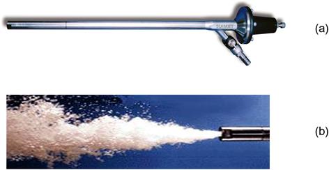
An example of an internal jetting sparger is the SlamJet® (Figure 12.77), which is a gas injection tube fitted with an air-actuated flowrate control and shut-off mechanism. The Sparjet (not shown) is a more recent design that includes a wear-protected nozzle with integrated needle-valve, which helps reduce fouling.
The external CISA/Microcel™ system (Figure 12.78) pumps slurry, drawn from the column, through an in-line contactor, where it mixes with and shears air into a bubble dispersion that is injected into the column (Brake and Eldridge, 1996). The external manifold system used to recycle slurry through the in-line contactor can be seen at the base of the column (the ring structure) in Figure 12.75(b).

Figure 12.79(a) shows an isometric (cutaway) drawing and an image of the cavitation tube (CavTube™) in operation. A slurry/gas mixture is fed to the CavTube™ where a pressure drop is established due to the internal geometry, which results in hydrodynamic cavitation to produce fine bubbles. The process may result in bubble nucleation and growth on the particle surface, augmenting bubble–particle collision as the collection mechanism. Reviews of the cavitation process and its role in flotation processes can be found elsewhere (Zhou et al., 1994, 1997, 2009). Frother addition assists the process of fine bubble production within the device. Similar to the CISA system, the CavTube™ is an external sparging system that requires slurry recirculation via a slurry manifold (Figure 12.79(b)).

12.13.3 Reactor/Separator Flotation Machines
Conventional flotation machines house two functions in a single vessel: an intense mixing region where bubble–particle collision and attachment occurs, and a quiescent region where the bubble–particle aggregates separate from the slurry. The reactor/separator machines decouple these functions into two separate (or sometime more) compartments. The cells are typically considered high-intensity machines due to the turbulent mixing in the reactor (see Section 12.9.5). The role of the separator is to allow sufficient time for mineralized bubbles to separate from the tailing stream which generally requires relatively short residence time (when compared to mechanical cells or columns).
Some of the earliest machine designs were of the reactor/separator-type. Figure 12.80 shows a design from a patent by Hebbard (1913). Feed slurry was mixed with entrained air in an agitation box (reactor) and flowed into the separation vessel where froth was collected as overflow. The design would be the basis for the Minerals Separation Corporation standard machine and early flotation cells used in the United States (Lynch et al., 2010).

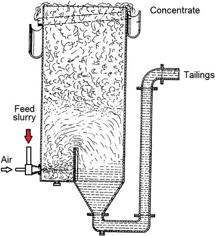
The Davcra cell (Figure 12.81) was developed in the 1960s and is considered to be the first high-intensity machine. The cell could be thought of as a column or reactor/separator device. Air and feed slurry are contacted and injected into the tank through a cyclone-type dispersion nozzle, the energy of the jet of pulp being dissipated against a vertical baffle. Dispersion of air and collection of particles by bubbles occurs in the highly agitated region of the tank, confined by the baffle. The pulp flows over the baffle into a quiescent region designed for bubble–pulp disengagement. Although not widely used, Davcra cells replaced some mechanical cleaner machines at Chambishi copper mine in Zambia, with reported lower operating costs, reduced floor area, and improved metallurgical performance.
Several attempts have been made to develop more compact column-type devices, the Jameson cell (Jameson, 1990; Kennedy, 1990; Cowburn et al., 2005) being a successful example (Figure 12.82). The Jameson cell was developed in the 1980s jointly by Mount Isa Mines Ltd and the University of Newcastle, Australia. The cell was first installed for cleaning duties in base metal operations (Clayton et al., 1991; Harbort et al., 1994), but it has also found use in coal plants and in roughing and preconcentrating duties. The original patent refers to the Jameson cell as a column method, but it can also be considered a reactor/separator machine: contact between the feed and the air stream is made using a plunging slurry jet in a vertical downcomer (the reactor), and the air–slurry mixture flows downwards to discharge and disengage into a shallow pool of pulp in the bottom of a short cylindrical tank (the separator). The disengaged bubbles rise to the top of the tank to overflow into a concentrate launder, while the tails are discharged from the bottom of the vessel. Air is self-aspirated (entrained) by the action of the plunging jet. The air rate is influenced by jet velocity and slurry density and level in the separator chamber.

The Jameson cell has been widely used in the coal industry in Australia since the 1990s. Figure 12.83 shows a typical cell layout where fine coal slurry feeds a central distributor which splits the stream to the downcomers. Clean coal is seen overflowing as concentrate from the separation vessel. The major advantage of the cell in this application is the ability to produce clean concentrates in one stage of operation by reducing entrainment, especially when wash water is used. It also has a novel application in copper solvent extraction/electrowinning circuits, where it is used to recover entrained organic droplets from electrolyte (Miller and Readett, 1992).

The Contact cell (Figure 12.84) was developed in the 1990s in Canada. The feed slurry is placed in direct contact with pressurized air in an external contactor which comprises a draft tube and an orifice plate. The slurry–air mixture is fed from the contactor to the column-type separation vessel, where mineralized bubbles rise to form froth. Contact cells employ froth washing similar to conventional flotation columns and Jameson cells. Contact cells have been implemented in operations in North America, Africa, and Europe.

The IMHOFLOT V-Cell (Figure 12.85(a)) was developed in the 1980–1990s and evolved from early pneumatic designs developed in Germany in the 1960–1970s (Imhof et al., 2005; Lynch et al., 2010). Conditioned feed pulp is mixed with air in an external self-aeration unit above the flotation cell. The air–slurry mixture descends a downcomer pipe and is introduced to the separation vessel via a distributor box and ring pipe with nozzles that redirect the flow upward in the cell. The separation vessel is fitted with an adjustable froth crowding cone which can be used to control mass pull. The concentrate overflows to an external froth launder, while the tailings stream exits at the base of the separation vessel. The V-Cell has been used to float sulfide and oxide ores with the largest operation being an iron ore application (Imhof et al., 2005).

The IMHOFLOT G-Cell (Figure 12.85(b)) was introduced in 2001 and employs the same external self-aerating unit as the V-Cell. The air–slurry mixture which exits the aeration unit is fed to an external distributor box (located above the separation vessel) where pulp is split and fed to the separation vessel tangentially via feed pipes. The cell is unusual as an internal launder located at the center of the vessel collects froth. The centrifugal motion of the slurry enhances froth separation with residence times being ca. 30 s.
The Staged Flotation Reactor (SFR) (Figure 12.86) is a recent development in the minerals industry. By sequencing the three processes—particle collection, bubble/slurry disengagement, and froth recovery—and assigning each to a purpose-built chamber, the SFR aims to optimize each of the three processes independently.

The SFR incorporates an agitator in the first (collection) chamber designed to provide high energy intensity (kW m−3) and induce multiple particle passes through the high shear impeller zone, hence giving high collection efficiency. Slurry flows by gravity through the reactor stages, that is, there is no need to apply agitation to suspend solids, only for particle collection. As such, impeller speed can be adjusted online in correlation with desired recovery without sanding. The second tank is designed to deaerate the slurry (bubble disengagement) and rapidly recover froth to the launder without dropback. The froth recovery unit is tailored for use of wash water and for high solids flux. Efficient particle collection and high froth recovery translate into fewer, smaller cells, resulting in a smaller footprint and building height, with lower power consumption, and the potential for good selectivity in both roughing and cleaning applications.
12.13.4 Specialized Flotation Machines
Several flotation machines have been developed specifically to treat fine and coarse particle streams where kinetics are typically low (Section 12.10.1). This section highlights commercially available equipment that has made in-roads for specific applications along with some promising designs that are in the development stage.
Flash Flotation
The process aims to float coarse, high-grade particles early in the process flowsheet. Typically, a portion of the cyclone underflow stream from the ball mill circuit (i.e., the circulating load) comprises the feed to the flash flotation cell, with the flotation tails returning to the grinding mill (Figure 12.87). The product can be directed to a final concentrate (but see comments in Section 12.10.2) or a middlings stream, depending upon the grade. Flash cells are used in a variety of base metal operations where dense minerals accumulate in the cyclone underflow, but draw much attention for gold recovery as gold tends to accumulate in the recirculating load, not only due to its high density but also due to gold’s malleability giving slow grinding kinetics (Banisi et al., 1991). The flash flotation cell is specifically designed with a sloped bottom and vertical discharge, which allows for by-pass of very coarse particles (Figure 12.88).


One of the earliest references to the concept was by Garrett (1933), who discussed experiments at North Broken Hill where ball mill discharge was directly floated in an eight-cell bank. Concentrate from the first three cells was directed to the final lead concentrate filters, with the remaining reporting to a middlings stream. In the early days of implementation, the machines were termed “unit cells.” Flash cells have been widely used since the 1980s in new operations and retrofitted in older concentrators.
Hydrofloat™ Separator
This device was developed in the 1990s, with the first unit being installed for coarse particle recovery in the potash industry. The Hydrofloat™ separator has since been used to recover coarse phosphates, diamonds, spodumene, and vermiculite. Preclassified feed (typically >250 µm) is processed in the machine, which incorporates hindered settling and flotation principles that allow for recovery of coarse particles (when compared to conventional flotation systems).
The HydroFloat™ consists of a circular tank subdivided into an upper separation chamber and a lower dewatering cone (Figure 12.89). The device operates much like a traditional hindered-bed separator, with the feed settling against an upward current of fluidization water. The fluidization (teeter) water is supplied through a network of pipes that extend across the bottom of the entire cross-sectional area of the separation chamber. The teeter bed is continuously aerated by injecting compressed air and a small amount of frothing agent into the fluidization water. The bubbles attach to the hydrophobic particles, reducing their density till they rise through the teeter bed and are floated off. The use of the dense-phase, fluidized bed eliminates axial mixing, increases coarse particle residence time, and increases the flotation rate by promoting bubble–particle interactions. As a result, the rate of recovery is high for both coarse liberated and semiliberated particles. Hydrophilic particles that do not attach to the air bubbles continue to move down through the teeter bed and eventually settle into the dewatering cone. These particles are discharged as a high solids stream (e.g., 75% solids) through a control valve at the bottom of the separator. The valve is actuated in response to a signal provided by a pressure transducer mounted to the side of the separation chamber. This configuration allows a constant effective density to be maintained within the teeter bed.

StackCell™
This technology has recently been developed and implemented for fine particle flotation (typically treating particles <150 µm), primarily for coal, but also in iron ore and copper processing. In the StackCell™ (Figure 12.90), feed slurry is mixed with low-pressure air (i.e., preaeration) and the aerated slurry then travels to the high-shear aerator (reactor) located at the center of the cell. This arrangement provides efficient bubble–particle contacting, substantially shortening the residence time required for particle collection and thus reducing cell volume requirements. It has been found (Williams and Crane, 1983) that the flotation rate is proportional to bubble concentration, hydrophobic particle concentration, and energy (Section 12.9.5). With the shearing and mixing energy concentrated within the aerator and used for the sole purpose of creating bubbles and increasing bubble–particle collisions, the flotation rate offered by the StackCell™ is higher than in conventional cells. Once the slurry leaves the aerator and enters the outer tank, phase separation occurs between the mineralized bubbles (forming froth) and the pulp. A pulp level is maintained in the outer tank to provide a deep froth that can be washed to minimize the entrainment of fine material. The froth overflows into a launder, while the tailings are discharged through a control valve. The system is specifically designed to have both a small footprint and a gravity-driven feed system. This allows multiple units to be “stacked” in series on subsequent levels in the plant or easily placed ahead of existing (potentially overloaded) flotation circuits.

Recently, two devices have been proposed by developers at the University of Newcastle, Australia, for fine particle flotation: the Concorde cell (Jameson, 2006) and the Reflux Flotation Cell (RFC) (Dickinson and Galvin, 2014).
The Concorde cell (Figure 12.91) is specifically designed to float particles less than 20 µm. The cell resembles a Jameson cell and consists of two stages (i.e., reactor/separator-type machine). Small bubbles are first formed in a “blast tube” under pressure (Jameson, 2010). Similar to the Jameson cell, the feed enters as a vertical jet, where it is mixed with air, but in this case the air is fed under pressure. The bubble/slurry mixture then passes through a choke and is accelerated and ultimately exceeds the speed of sound (travelling at ca. 20 m s−1) (Jameson, 2010), which creates shock waves. The rapid pressure change in the choke results in fine bubble formation. The bubble/slurry mixture exits the choke and is fed to an impingement bowl, which redirects the flow upward into the separation vessel. Mineralized bubbles float to form froth and overflow, while the tailings stream exits via the bottom of the vessel. To date, pilot-scale tests have been undertaken (Jameson, 2010).

A diagram of the RFC is shown in Figure 12.92. Air is introduced vertically downward through a sintered sparger which is inserted into a vertical feed tube. Feed slurry is introduced to the tube and flows over the sparger, forming bubbles. The air/slurry mixture flows downward into the separation vessel. The separation vessel includes parallel inclined channels (PICs) toward the base, through which the tailings stream passes. The PICs increase the segregation of the bubbles from the tailings stream, which minimizes the loss of mineralized bubbles (Dickinson and Galvin, 2014). A feature of the RFC is that the top of the vessel is enclosed and froth is confined to a reduced area overflow outlet. Fluidization water is added via a distributor below the overflow. The RFC design allows for higher gas and wash water fluxes when compared to conventional machines.