
Crushers
Crushing is the first mechanical stage in the process of comminution in which a principal objective is the liberation of the valuable minerals from the gangue. Crushing is typically a dry operation which is performed in two- or three-stages (i.e., primary, secondary, and tertiary crushing). Lumps of run-of-mine ore as large as 1.5 m across are reduced in the primary crushing stage to 10–20 cm in heavy-duty machines.
Keywords
Primary crushers; secondary crushers; high pressure grinding rolls; impact crushers; circuits and control
6.1 Introduction
Crushing is the first mechanical stage in the process of comminution in which a principal objective is the liberation of the valuable minerals from the gangue. Crushing is typically a dry operation that is performed in two- or three-stages (i.e., primary, secondary, tertiary crushing). Lumps of run-of-mine ore as large as 1.5 m across are reduced in the primary crushing stage to 10–20 cm in heavy-duty machines.
In most operations, the primary crushing schedule is the same as the mining schedule. When primary crushing is performed underground it is normally a responsibility of the mining department; for primary crushing at the surface it is customary for the mining department to deliver the ore to the crusher and for the mineral processing department to crush and handle the ore from this point through the successive ore-processing stages. Primary crushers are commonly designed to operate 75% of the available time, mainly due to interruptions caused by insufficient crusher feed and mechanical delays (Lewis et al., 1976; McQuiston and Shoemaker, 1978; Major, 2002).
Primary crusher product from most metalliferous ores can be crushed and screened satisfactorily, and subsequent crushing consists of one or two size-reduction stages with appropriate crushers and screens (Major, 2002). In three-stage circuits, ore is reclaimed from ore storage with secondary crushing product typically ranging from 3.7–5.0 cm, and tertiary crushing further reducing the ore to ca. 0.5–2 cm in diameter. The product size is determined by the size of the opening at the discharge, called the set or setting. The reduction ratio is the ratio of feed size to product size, often with reference to the 80% passing size, that is, reduction ratio=F80/P80. If the ore tends to be slippery and tough, the tertiary crushing stage may be substituted by coarse grinding. On the other hand, more than three size-reduction stages may be required if the ore is extra-hard, or in special cases where it is important to minimize the production of fines (Major, 2009).
Vibrating screens are sometimes placed ahead of secondary or tertiary crushers to remove undersize material (i.e., scalp the feed), thereby increasing the capacity of the crushing plant. Undersize material tends to pack the voids between large particles in the crushing chamber, and can choke the crusher, causing damage, because the packed mass of rock is unable to swell in volume as it is broken.
Crushing may be in open- or closed-circuit, depending on the required product size distribution. Two basic crushing flowsheets are shown in Figure 6.1: (a) the older style (“traditional”) 3-stage crushing circuit ahead of a rod mill, and (b) the more modern open-circuit primary crushing prior to SAG milling with crushing and recycling of “critical size” material (see Chapters 5 and 7 for discussion on “critical size”). Both flowsheets show the primary crusher is in open circuit. Figure 6.1(a) shows the secondary crusher operating in open-circuit while the tertiary crusher is closed with the screen undersize feeding the rod mill. In open-circuit crushing there is no recycle of crusher product to the feed. Open-circuits may include scalping ahead of the crushers with undersize material from the screen being combined with the crusher product, which is then routed to the next operation. If the crusher is producing rod mill (or ball mill) feed, it is good practice to use final stage closed-circuit crushing in which the undersize from the screen feeds the mill. The crusher product is returned to the screen so that any over-size material is recirculated. To meet the tonnage and product size requirements there may be more than one secondary and tertiary crusher operating in parallel with the feed split between the units. The various circuits are illustrated by Major (2002).

One of the main reasons for closing the circuit is the greater flexibility given to the crushing plant as a whole. The crusher can be operated at a wider setting if necessary, thus altering the size distribution of the product, and by making a selective cut on the screen, the finished product can be adjusted to give the required specification. There is the added factor that if the material is wet or sticky (potentially due to climatic conditions) it is possible to open the setting of the crusher to prevent the possibility of packing, and by this means the throughput of the machine is increased, which will compensate for the additional circulating load. Closed-circuit operation also allows compensation for wear that takes place on liners, and generally gives greater freedom to meet changes in requirements from the plant.
Surge bins precede the primary crusher to receive dumped loads from ships or trucks and should have enough storage capacity to maintain a steady feed to the crusher. In most mills the crushing plant does not run for 24 h a day, as hoisting and transport of ore is usually carried out on two shifts only, the other shift being used for drilling and blasting. The crushing section must therefore have a greater hourly capacity than the rest of the plant, which is run continuously. Crushed ore surge capacity is generally included in the flowsheet to ensure continuous supply to the grinding circuit. The obvious question is, why not have similar storage capacity before the crushers and run this section continuously also? Apart from the fact that it is cheaper in terms of power consumption to crush at off-peak hours, large storage bins are expensive, so it is uneconomic to have bins at both the crushing and grinding stages. It is not practical to store large quantities of run-of-mine (ROM) ore, as it consists of a large range of particle sizes and the small ones move down in the pile and fill the voids. This packed mass is difficult to move after it has settled. ROM ore should therefore be kept moving as much as possible, and surge bins should have sufficient capacity only to even out the flow to the crusher.
6.2 Primary Crushers
Primary crushers are heavy-duty machines, used to reduce ROM ore down to a size suitable for transport and for feeding the secondary crushers or AG/SAG mills. The units are always operated in open circuit, with or without heavy-duty scalping screens (grizzlies). There are two main types of primary crushers in metalliferous operations: jaw and gyratory crushers, although impact crushers have limited use as primaries and will be considered separately. Scalping is typically associated with jaw crusher circuits and can be included to maximize throughput.
6.2.1 Jaw Crushers
The Blake crusher was patented by E.W. Blake in 1858 and variations in detail on the basic form are found in most of the jaw crushers used today. The patent states that the stone breaker “consists of a pair of jaws, one fixed and the other movable, between which the stones are to be broken.” The jaws are set at an acute angle with one jaw pivoting so as to swing relative to the other fixed jaw. Material fed into the jaws is repetitively nipped and released to fall further into the crushing chamber until the discharge aperture.
Jaw crushers are classified by the method of pivoting the swing jaw (Figure 6.2). In the Blake crusher, the jaw is pivoted at the top and thus has a fixed receiving area and a variable discharge opening. In the Dodge crusher, the jaw is pivoted at the bottom, giving it a variable feed area but fixed delivery area. The Dodge crusher is restricted to laboratory use, where close sizing is required. The Universal crusher is pivoted in an intermediate position, and thus has a variable delivery and receiving area.

There are two forms of the Blake crusher: double toggle and single toggle.
In double-toggle Blake crushers, the oscillating movement of the swinging jaw is effected by vertical movement of the pitman, which moves up and down under the influence of the eccentric (Figure 6.3). The back toggle plate causes the pitman to move sideways as it is pushed upward. This motion is transferred to the front toggle plate, which in turn causes the swing jaw to close on the fixed jaw, this minimum separation distance being the closed set (or closed side setting). Similarly, downward movement of the pitman allows the swing jaw to open, defining the open set (or open side setting).

The important features of the machine are:
1. Since the jaw is pivoted from above, it moves a minimum distance at the entry point and a maximum distance at the delivery. This maximum distance is called the throw of the crusher, that is, the difference between the open side and closed side settings.
2. The horizontal displacement of the swing jaw is greatest at the bottom of the pitman cycle and diminishes steadily through the rising half of the cycle as the angle between the pitman and the back toggle plate becomes less acute.
3. The crushing force is least at the start of the cycle, when the angle between the toggles is most acute, and is strongest at the top of the cycle, when full power is delivered over a reduced travel of the jaw.
Figure 6.3 shows a cross section through a double-toggle jaw crusher. Jaw crushers are rated according to their receiving area, that is, the gape, which is the distance between the jaws at the feed opening, and the width of the plates. For example, a 1,220×1,830 mm crusher has a gape of 1,220 mm and a width of 1,830 mm.
Consider a large piece of rock falling into the mouth of the crusher. It is nipped by the jaws, which are moving relative to each other at a rate depending on the size of the machine (and which usually varies inversely with the size). Basically, time must be given for the rock broken at each “bite” to fall to a new position before being nipped again. The ore falls until it is arrested. The swing jaw closes on it, quickly at first, and then more slowly with increasing power toward the end of the stroke. The fragments fall to a new arrest point as the jaws open and are gripped and crushed again. During each “bite” of the jaws, the rock swells in volume due to the creation of voids between the particles. Since the ore is also falling into a gradually reducing cross sectional area of the crushing chamber, choking of the crusher would soon occur if it were not for the increasing amplitude of swing toward the discharge end of the crusher. This accelerates the material through the crusher, allowing it to discharge at a rate sufficient to leave space for material entering from above. This is termed arrested or free crushing as opposed to choked crushing, which occurs when the volume of material arriving at a particular cross section is greater than that leaving. In arrested crushing, crushing is by the jaws only, whereas in choked crushing, particles break one other. This inter-particle comminution can lead to excessive production of fines, and if choking is severe can damage the crusher.
The discharge size of material from the crusher is controlled by the open side set, which is the maximum opening of the jaws at the discharge end. This can be adjusted by using toggle plates of the required length. The back pillow into which the back toggle plate bears can be adjusted to compensate for jaw wear. A number of manufacturers offer jaw setting by hydraulic jacking, and some fit electro-mechanical systems, which allow remote control (Anon., 1981).
A feature of all jaw crushers is the heavy fly-wheel (seen at the back of Figure 6.3(b)) attached to the drive, which is necessary to store energy on the idling half of the stroke and deliver it on the crushing half. Since the jaw crusher works on half-cycle only, it is limited in capacity for its weight and size. Due to the alternate loading and release of stress, jaw crushers must be rugged and require strong foundations to accommodate the vibrations.
In single-toggle jaw crushers (Figure 6.4) the swing jaw is suspended on the eccentric shaft, which allows a lighter, more compact design than with the double-toggle machine. The motion of the swing jaw also differs from that of the double-toggle design. Not only does the swing jaw move toward the fixed jaw under the action of the toggle plate, but it also moves vertically as the eccentric rotates. This elliptical jaw motion assists in pushing rock through the crushing chamber. The single-toggle machine therefore has a somewhat higher capacity than the double-toggle machine of the same gape. The eccentric movement, however, increases the rate of wear on the jaw plates. Direct attachment of the swing jaw to the eccentric imposes a high degree of strain on the drive shaft, and as such maintenance costs tend to be higher than with the double-toggle machine.

Double-toggle machines are usually used on tough, hard and abrasive material. This being said, single-toggle crusher do see use (primarily in Europe) for heavy-duty work on tough taconite ores, and it is often choke fed, since the jaw movement tends to make it self-feeding.
Jaw-crusher Construction
Jaw crushers are heavy-duty machines and hence must be robustly constructed. The main frame is often made from cast iron or steel, connected with tie-bolts. It is commonly made in sections so that it can be transported underground for installation. Modern jaw crushers may have a main frame of welded mild steel plate.
The jaws are usually constructed from cast steel and fitted with replaceable liners, made from manganese steel, or “Ni-hard,” a Ni-Cr alloyed cast iron. Apart from reducing wear, hard liners are essential to minimize crushing energy consumption by reducing the deformation of the surface at each contact point. The jaw plates are bolted in sections for simple removal or periodic reversal to equalize wear. Cheek plates are fitted to the sides of the crushing chamber to protect the main frame from wear. These are also made from hard alloy steel and have similar lives to the jaw plates. The jaw plates may be smooth, but are often corrugated, the latter being preferred for hard, abrasive ores. Patterns on the working surface of the crushing members also influence capacity, especially at small settings. The corrugated profile is claimed to perform compound crushing by compression, tension, and shearing. Conventional smooth crushing plates tend to perform crushing by compression only, though irregular particles under compression loading might still break in tension. Since rocks are around 10 times weaker in tension than compression, power consumption and wear costs should be lower with corrugated profiles. Regardless, some type of pattern is desirable for the jaw plate surface in a jaw crusher, partly to reduce the risk of undesired large flakes easily slipping through the straight opening, and partly to reduce the contact surface when crushing flaky blocks. In several installations, a slight wave shape has proved successful. The angle between the jaws is usually less than 26°, as the use of a larger angle causes particle to slip (i.e., not be nipped), which reduces capacity and increases wear.
In order to overcome problems of choking near the discharge of the crusher, which is possible if fines are present in the feed, curved plates are sometimes used. The lower end of the swing jaw is concave, whereas the opposite lower half of the fixed jaw is convex. This allows a more gradual reduction in size as the material nears the exit, minimizing the chance of packing. Less wear is also reported on the jaw plates, since the material is distributed over a larger area.
The speed of jaw crushers varies inversely with the size, and usually lies in the range of 100–350 rpm. The main criterion in determining the optimum speed is that particles must be given sufficient time to move down the crusher throat into a new position before being nipped again.
The throw (maximum amplitude of swing of the jaw) is determined by the type of material being crushed and is usually adjusted by changing the eccentric. It varies from 1 to 7 cm depending on the machine size, and is highest for tough, plastic material and lowest for hard, brittle ore. The greater the throw the less danger of choking, as material is removed more quickly. This is offset by the fact that a large throw tends to produce more fines, which inhibits arrested crushing. Large throws also impart higher working stresses to the machine.
In all crushers, provision must be made for avoiding damage that could result from uncrushable material entering the chamber. Many jaw crushers are protected from such “tramp” material (often metal objects) by a weak line of rivets on one of the toggle plates, although automatic trip-out devices are now common. Certain designs incorporate automatic overload protection based on hydraulic cylinders between the fixed jaw and the frame. In the event of excessive pressure caused by an overload, the jaw is allowed to open, normal gap conditions being reasserted after clearance of the blockage. This allows a full crusher to be started under load (Anon., 1981). The use of “guard” magnets to remove tramp metal ahead of the crusher is also common (Chapters 2 and 13).
Jaw crushers are supplied in sizes up to 1,600 mm (gape)×1,900 mm (width). For coarse crushing application (closed set~300 mm), capacities range up to ca. 1,200 t h−1. However, Lewis et al. (1976) estimated that the economic advantage of using a jaw crusher over a gyratory diminishes at crushing rates above 545 t h−1, and above 725 t h−1 jaw crushers cannot compete.
6.2.2 Gyratory Crushers
Gyratory crushers are principally used in surface-crushing plants. The gyratory crusher (Figure 6.5) consists essentially of a long spindle, carrying a hard steel conical grinding element, the head, seated in an eccentric sleeve. The spindle is suspended from a “spider” and, as it rotates, normally between 85 and 150 rpm, it sweeps out a conical path within the fixed crushing chamber, or shell, due to the gyratory action of the eccentric. As in the jaw crusher, maximum movement of the head occurs near the discharge. This tends to relieve the choking due to swelling. The gyratory crusher is a good example of arrested crushing. The spindle is free to turn on its axis in the eccentric sleeve, so that during crushing the lumps are compressed between the rotating head and the top shell segments, and abrasive action in a horizontal direction is negligible.

With a gyratory crusher, at any cross section there are in effect two sets of jaws opening and shutting like jaw crushers. In fact, the gyratory crusher can be regarded as an infinitely large number of jaw crushers each of infinitely small width, and, as consequence, the same terms gape, set, and throw, have identical meaning in the case of the gyratory crusher. Since the gyratory, unlike the jaw crusher, crushes on full cycle, it has a higher capacity than a jaw crusher of the same gape, roughly by a factor of 2.5–3, and is usually favored in plants handling large throughputs: in mines with crushing rates above 900 t h−1, gyratory crushers are always selected.
Gyratory crushers are identified by the size of the gape and the size of the mantle at the discharge. They range in size up to ca. 1,600 mm×2,900 mm (gape×mantle diameter) with power consumption as high as 1,200 kW and capable of crushing up to ca. 10,000 t h−1 at a discharge open side setting up to 240 mm.
Large gyratories typically dispense with expensive feeding mechanisms and are often fed direct from trucks (Figure 6.6). They can be operated with the head buried in feed. Although excessive fines may have to be “scalped” from the feed (more common in jaw crushing circuits), the trend in large-capacity plants with gyratory crushers is to dispense with grizzlies. This reduces capital cost of the installation and reduces the height from which the ore must fall into the crusher, thus minimizing damage to the spider. Choked crushing is encouraged to some extent as rock-to-rock crushing in primary stages reduces the rock-to-steel crushing required in the secondary crushers, thus reducing wear (McQuiston and Shoemaker, 1978). Choke feeding of a gyratory crusher has been claimed beneficial when the crusher is followed by SAG mills, as their throughput is sensitive to the mill feed size (Simkus and Dance, 1998). Operating crushers under choke feeding conditions gives more even wear and longer crusher life.

The last ten years or so have seen advances in increased installed power which, without increasing crusher size, has increased capacity (Erikson, 2014). Other innovations have been in serviceability, and measurement of wear components (Erikson, 2014).
Gyratory Crusher Construction
The outer shell of the crusher is constructed from heavy steel casting or welded steel plate, with at least one constructional joint, the bottom part taking the drive shaft for the head, the top, and lower shells providing the crushing chamber. If the spindle is carried on a suspended bearing, as in most primary gyratories, then the spider carrying the bearing forms a joint across the reinforced alloyed white cast-iron (Ni-hard) liners or concaves. In smaller crushers, the concave is one continuous ring bolted to the shell. Large machines use sectionalized concaves, called staves, which are wedge-shaped, and either rest on a ring fitted between the upper and the lower shell, or are bolted to the shell. The concaves are backed with some soft filler material, such as white metal, zinc, or plastic cement, which ensures even seating against the steel bowl.
The head consists of the steel forgings, which make up the spindle. The head is protected by a mantle (usually of manganese steel) fastened to the head by means of nuts on threads which are pitched so as to be self-tightening during operation. The mantle is typically backed with zinc, plastic cement, or epoxy resin. The vertical profile is often bell-shaped to assist the crushing of material that has a tendency to choke. Figure 6.7 shows a gyratory crusher head during installation.

Some gyratory crushers have a hydraulic mounting and, when overloading occurs, a valve is tripped which releases the fluid, thus dropping the spindle and allowing the “tramp” material to pass out between the head and the bowl. The mounting is also used to adjust the set of the crusher at regular intervals to compensate for wear on the concaves and mantle. Many crushers use simple mechanical means to control the set, the most common method being by the use of a ring nut on the main shaft suspension.
6.2.3 Crusher Capacity
Because of the complex action of jaw and gyratory crushers, formulae expressing their capacities have never been entirely satisfactory. Crushing capacity depends on many factors, such as the angle of nip (i.e., the angle between the crushing members), stroke, speed, and the liner material, as well as the feed material and its initial particle size. Capacity problems do not usually occur in the upper and middle sections of the crushing cavity, providing the angle of nip is not too great. It is normally the discharge zone, the narrowest section of the crushing chamber, which determines the crushing capacity.
Broman (1984) describes the development of simple models for optimizing the performance of jaw and gyratory crushers. The volumetric capacity (Q, m3 h−1) of a jaw crusher is expressed as:
(6.1)
where B=inner width of crusher (m); S=open side setting (m); s=throw (m); a=angle of nip; n=speed of crusher (rpm); and k is a material constant which varies with the characteristics of the crushed material, the feeding method, liner type, etc., normally having values between 1.5 and 2.
For gyratory crushers, the corresponding formula is:
(6.2)
where D=diameter of the head mantle at the discharge point (m), and k, the material constant, normally varying between 2 and 3.
6.2.4 Selection of a Jaw or Gyratory Crusher
As noted, in deciding whether a jaw or a gyratory crusher should be used, the main factor is the maximum size of ore which the crusher will be required to handle and the throughput required. Gyratory crushers are, in general, used where high capacity is required. Jaw crushers tend to be used where the crusher gape is more important than the capacity. For instance, if it is required to crush material of a certain maximum diameter, then a gyratory having the required gape would have a capacity about three times that of a jaw crusher of the same gape. If high capacity is required, then a gyratory is the answer. If, however, a large gape is needed but not capacity, then the jaw crusher will probably be more economical, as it is a smaller machine and the gyratory would be running idle most of the time. A guiding relationship was that given by Taggart (1945): if t h−1<161.7×(gape in m2), use a jaw crusher; conversely, if the tonnage is greater than this value, use a gyratory crusher.
There are some secondary considerations. The capital and maintenance costs of a jaw crusher are slightly less than those of the gyratory but they may be offset by the installation costs, which are lower for a gyratory, since it occupies about two-thirds the volume and has about two-thirds the weight of a jaw crusher of the same capacity. The circular crushing chamber allows for a more compact design with a larger proportion of the total volume being accounted for by the crushing chamber. Jaw-crusher foundations need to be much more rugged than those of the gyratory, due to the alternating working stresses.
In some cases, the self-feeding capability of the gyratory compared with the jaw results in a capital cost saving, as expensive feeding devices, such as the heavy-duty chain feeders (Chapter 2), may be eliminated. In other cases, the jaw crusher has found favor, due to the ease with which it can be shipped in sections to remote locations and for installation underground.
The type of material being crushed may also determine the crusher used. Jaw crushers perform better than gyratories on clay or plastic materials due to their greater throw. Gyratories have been found to be particularly suitable for hard, abrasive material, and they tend to give a more cubic product than jaw crushers if the feed is laminated or “slabby.”
6.3 Secondary/tertiary Crushers
Secondary crushers are lighter than the heavy-duty, rugged primary machines. The bulk of secondary/tertiary crushing of metalliferous ores is performed by cone crushers. Since they take the primary crushed ore as feed, the maximum feed size will normally be less than 15 cm in diameter and, because most of the harmful constituents in the ore, such as tramp metal, wood, clays, and slimes have already been removed, it is much easier to handle. Similarly, the transportation and feeding arrangements serving the crushers do not need to be as rugged as in the primary stage. Secondary/tertiary crushers also operate with dry feeds, and their purpose is to reduce the ore to a size suitable for grinding (Figure 6.1(a)). Tertiary crushers are, to all intents and purposes, of the same design as secondaries, except that they have a closer set.
6.3.1 Cone Crushers
The cone crusher is a modified gyratory crusher, and accordingly many of the same terms including gape, set, and throw, apply. The essential difference is that the shorter spindle of the cone crusher is not suspended, as in the gyratory, but is supported in a curved, universal bearing below the gyratory head or cone (Figure 6.8). Major suppliers of cone crushers include Metso (GP, HP, and MP Series), FLSmidth (Raptor® Models) and Sandvik (CS- and CH-series, developed from the Allis Chalmers Hydrocone Series), who manufacture a variety of machines for coarse and fine crushing applications.

Power is transmitted from the source to the countershaft through a V-belt or direct drive. The countershaft has a bevel pinion pressed and keyed to it, and drives the gear on the eccentric assembly. The eccentric has a tapered, offset bore and provides the means whereby the head and main shaft follow an eccentric path during each cycle of rotation.
Since a large gape is not required, the crushing shell or bowl flares outwards, which allows for the swell of broken ore by providing an increasing cross sectional (annular) area toward the discharge end. The cone crusher is therefore an excellent arrested crusher. The flare of the bowl allows a much greater head angle than in the gyratory crusher, while retaining the same angle between the crushing members. This gives the cone crusher a high capacity, since the capacity of gyratory crushers is roughly proportional to the diameter of the head.
The head is protected by a replaceable mantle, which is held in place by a large locking nut threaded onto a collar bolted to the top of the head. The mantle is backed with plastic cement, or zinc, or more recently with an epoxy resin.
Unlike a gyratory crusher, which is identified by the dimensions of the feed opening and the mantle diameter, a cone crusher is rated by the diameter of the cone mantle. Cone crushers are also identified by the power draw: for example, the Metso MP1000 refers to 1,000 HP (746 kW), and the FLSmidth XL2000 refers to 2,000 HP (1,491 kW). As with gyratories, one advance has been to increase power draw (Erikson, 2014). The largest unit is the Metso MP2500 recently installed at First Quantum Minerals’ Sentinel mine in Zambia with capacity of 3,000 to 4,500 t h−1 (Anon., 2014). The increase in cone crusher capacity means they better match the capacity of the primary gyratories, simplifying circuits, which in the past could see several secondary and especially tertiary cone crushers in parallel (Major, 2002).
The throw of cone crushers can be up to five times that of primary crushers, which must withstand heavier working stresses. They are also operated at much higher speeds (700–1,000 rpm). The material passing through the crusher is subjected to a series of hammer-like blows rather than being gradually compressed as by the slowly moving head of the gyratory crusher.
The high-speed action allows particles to flow freely through the crusher, and the wide travel of the head creates a large opening between it and the bowl when in the fully open position. This permits the crushed fines to be rapidly discharged, making room for additional feed. The fast discharge and non-choking characteristics of the cone crusher allow a reduction ratio in the range 3:1–7:1, but this can be higher in some cases.
The classic Symons cone crusher heads were produced in two forms depending on the application: the standard (Figure 6.9(a)) for normal secondary crushing and the short-head (Figure 6.9(b)) for fine, or tertiary duty. They differ mainly in the shape of their crushing chambers. The standard cone has “stepped” liners, which allow a coarser feed than in the short-head, and delivers a product varying from ca. 0.5 to 6 cm. The short-head has a steeper head angle than the standard, which helps to prevent choking from the much finer material being handled. It also has a narrower feed opening and a longer parallel section at the discharge, and delivers a product of ca. 0.3–2.0 cm. Contemporary secondary (Figure 6.9(c)) and tertiary (Figure 6.9(d)) cone crusher designs have evolved and geometry varies depending on the ore type, feed rate, and feed and product particle size.

The parallel section between the liners at the discharge is a feature of all cone crushers and is incorporated to maintain a close control on product size. Material passing through the parallel zone receives more than one impact from the crushing members. This tends to give a product size dictated by the closed set rather than the open set. The distributing plate on the top of the cone helps to centralize the feed, distributing it at a uniform rate to the entire crushing chamber. An important feature of the crusher is that the bowl is held down either by an annular arrangement of springs or by a hydraulic mechanism. These allow the bowl to yield if uncrushable “tramp” material enters the crushing chamber, so permitting the offending object to pass. (The presence of such tramp material is readily identified by the noise and vibration caused on its passage through the chamber.) If the springs are continually activated, as may happen with ores containing many tough particles, oversize material will be allowed to escape from the crusher. This is one of the reasons for using closed-circuit crushing in the final stages. It may be necessary to choose a screen for the circuit that has apertures slightly larger than the set of the crusher (Example 6.1). This is to reduce the tendency for very tough particles, which are slightly oversize, to “spring” the crusher, causing an accumulation of such particles in the closed-circuit and a build-up of pressure in the crushing throat.
Example 6.1
For the circuit Figure ex 6.1 and the given data:

Fresh feed to the circuit (N)=200 t h−1
Fraction finer than screen opening (n)=20%
Screen opening (aperture)=13 mm
Screen efficiency (EU, see Chapter 8)=90%
Crusher options:
| Crusher Model | Crusher Capacity t h−1 (10 mm c.s.s.) |
| Model #1 | 140–175 |
| Model #2 | 175–220 |
| Model #3 | 260–335 |
Note: In Figure ex 6.1, upper case variables denote solids flow rates, t h-1, and lower case variables the fraction less than the screen opening, % (Table ex 6.1).
Table ex 6.1
Crusher Product Gradation Table (wt% passing particle size for given c.s.s.)a
| Particle size, mm | C.S.S., mm | |||
| 8 | 10 | 13 | 16 | |
| 20 | 100 | 100 | 100 | 90 |
| 13 | 100 | 90 | 80 | 64 |
| 10 | 100 | 80 | 64 | 54 |
| 8 | 93 | 68 | 55 | 45 |
| 7 | 74 | 60 | 50 | 40 |
| 6 | 68 | 50 | 45 | 35 |
| 5 | 60 | 45 | 38 | 30 |
| 4 | 50 | 38 | 32 | 24 |
| 3 | 40 | 30 | 26 | 18 |

aBased on Metso Crushing and Screening Handbook, 5th Edn.
Solution
Part 1
Solve for circulating load, R/U as follows:
At feed node to screen F=N+R=U+R
By dividing by U ![]()
substituting Ff=U/EU ![]()
then, re-arranging ![]()
From the crusher product gradation table provided:
Thus solving for R (=O) where U (=N)=200 t h−1:
![]()
R=202.5 t h−1
From the crusher capacity data, choice is model #2.
Part 2
Feed rate to the screen F=N+R=402.5 t h−1
This illustrates the approach to crusher sizing (as well as giving an exercise in identifying the balances). The approach is described in detail in Mular and Jergensen (1982) and Mular et al. (2002). Crusher suppliers, of course, have propriety methods of selecting and sizing units for a given duty.
The set on the crusher can easily be changed, or adjusted for liner wear, by screwing the bowl up or down by means of a capstan and chain arrangement or by adjusting the hydraulic setting, which allows the operator to change settings even if the equipment is operating under maximum load (Anon., 1985). To close the setting, the operator opens a valve which pumps hydraulic oil to the cylinder supporting the crusher head. To open the setting, another valve is opened, allowing the oil to flow out of the cylinder. Efficiency is enhanced through automatic tramp iron clearing and reset. When tramp iron enters the crushing chamber, the crushing head will be forced down, causing hydraulic oil to flow into the accumulator. When the tramp iron has passed from the chamber, nitrogen pressure forces the hydraulic oil from the accumulator back into the supporting hydraulic cylinder, thus restoring the original setting.
Wet Crushing
In 1988 Nordberg Inc. introduced wet tertiary cone crushing at a Brazilian lead-zinc mine (Karra, 1990). The Water Flush technology (now supplied by Metso) uses a cone crusher incorporating special seals, internal components, and lubricants to handle the large flow of water, which is added to the crusher to produce a product slurry containing 30–50% solids by weight, that can be fed directly to ball mills. The flushing action permits tighter closed side settings (Major, 2009). Such technology has potential for the crushing of sticky ores, for improving productivity in existing circuits, and for developing more cost-effective circuits. However, the presence of water during crushing can increase the liner wear rates, depending on the application.
Wear
Maintenance of the wear components in both gyratory and cone crushers is one of the major operating costs. Wear monitoring is possible using a Faro Arm (Figure 6.10), which is a portable coordinate measurement machine. Ultrasonic profiling is also used. A more advanced system using a laser scanner tool to profile the mantle and concave produces a 3D image of the crushing chamber (Erikson, 2014). Some of the benefits of the liner profiling systems include: improved prediction of mantle and concave liner replacement; identifying asymmetric and high wear areas; measurement of open and closed side settings; and quantifying wear life with competing liner alloys.

6.3.2 The Gyradisc® Crusher
The Gyradisc® crusher is a specialized form of cone crusher, used for producing finer material, which has found application in the quarrying industry (primarily sand and gravel) for the production of large quantities of sand at economic cost.
The main modification to the conventional cone crusher is a shorter crushing member, with the lower one being at a flatter angle (Figure 6.11). Crushing is by inter-particle comminution by the impact and attrition of a multi-layered mass of particles.

The angle of the lower member is less than the angle of repose of the ore, so that when at rest the material does not slide. Transfer through the crushing zone is by movement of the head. Each time the lower member moves away from the upper, material enters the attrition chamber from the surge load above. When reduction begins, material is picked up by the lower member and is moved outward. Due to the slope, it is carried to an advanced position and caught between the crushing members.
The length of stroke and the timing are such that after the initial stroke the lower member is withdrawn faster than the previously crushed material falls by gravity. This permits the lower member to recede and return to strike the previously crushed mass as it is falling, thus scattering it so that a new alignment of particles is obtained prior to another impact. At each withdrawal of the head, the void is filled by particles from the surge chamber.
At no time does single-layer crushing occur. Crushing is by particle on particle, so that the setting of the crusher is not as directly related to the size of product as it is on the cone crusher. When used in open circuit, the Gyradisc® will produce a product of chippings from about 1 cm downwards, of good cubic shape, with a satisfactory amount of sand, which obviates the use of blending and re-handling. In closed circuit, they are used to produce large quantities of sand. They may be used in open circuit on clean metalliferous ores with no primary slimes to produce an excellent ball-mill feed. Feeds of less than 19 mm may be crushed to about 3 mm (Lewis et al., 1976).
6.3.3 The Rhodax® Crusher
The Rhodax® crusher is another specialized form of cone crusher, referred to as an inertial cone crusher. Developed by FCB (now Fives fcb) Research Center in France, the Rhodax® crusher is claimed to offer process advantages over conventional cone crushers and is based on inter-particle compression crushing. It consists of a frame supporting a cone and a mobile ring, and a set of rigid links forming ties between the two parts (Figure 6.12). The frame is supported on elastic suspensions isolating the environment from dynamic stresses created by the crushing action. It contains a central shaft fixed on a structure. A grinding cone is mounted on this shaft and is free to rotate. A sliding sleeve on this shaft is used to adjust the vertical position of the cone and therefore the setting, making it simple to compensate for wear. The ring structure is connected to the frame by a set of tie rods. The ring and the cone are made of wear resistant steel.

One set of synchronized unbalanced masses transmits a known and controlled crushing force to the ring when the masses rotate. This fragmentation force stays constant even if the feed varies, or an unbreakable object enters the crushing chamber. The Rhodax® is claimed to achieve reduction ratios varying from 4 to more than 30 in open circuit. The relative positions of the unbalanced masses can be changed if required, so the value of the crushing force can thus be remotely controlled. As feed particles enter the fragmentation chamber, they slowly advance between the cone and the moving ring. These parts are subjected to horizontal circular translation movements and move toward and away from each other at a given point.
During the approach phase, materials are subjected to compression, up to 10–50 MPa. During the separation phase, fragmented materials pass further down in the chamber until the next compression cycle. The number of cycles is typically 4 to 5 before discharge. During these cycles the cone rolls on a bed of stressed material a few millimeters thick, with a rotation speed of a 10–20 rpm. This rotation is actually an epicyclical movement, due to the lack of sliding friction between the cone and the feed material. The unbalanced masses rotate at 100–300 rpm. The following three parameters can be adjusted on the Rhodax® crusher: the gap between the cone and the ring, the total static moment of unbalanced masses, and the rotation speed of these unbalanced masses.
The combination of the latter two parameters enables the operator to fix the required fragmentation force easily and quickly. Two series of machines have been developed on this basis, one for the production of aggregates (maximum pressure on the material bed between 10 and 25 MPa), and the other for feeds to grinding (25–50 MPa maximum pressure on the material bed). Given the design of the machine (relative displacement of two non-imposed wear surfaces), the product size distribution is independent of the gap and wear. These are distinct advantages over conventional cone crushers, which suffer problems with the variable product quality caused by wear.
6.3.4 A Development in Fine Crushing
IMP Technologies Pty. Ltd. has recently tested a pilot-scale super fine crusher that operates on dry ore and is envisaged as a possible alternative to fine or ultra-fine grinding circuits (Kelsey and Kelly, 2014). The unit includes a rotating compression chamber and an internal gyrating mandrel (Figure 6.13). Material is fed into the compression chamber and builds until the gyratory motion of the mandrel is engaged. Axial displacement of the compression chamber and the gyratory motion of the mandrel result in fine grinding of the feed material. In one example, a feed F80 of 300 μm was reduced to P80 of 8 μm, estimated to be the equivalent to two stages of grinding. This development is the latest in a resurgence in crushing technology resulting from the competition of AG/SAG milling and the demands for increased comminution energy efficiency.
6.3.5 Roll Crushers
Although not widely used in the minerals industry, roll crushers can be effective in handling friable, sticky, frozen, and less abrasive feeds, such as limestone, coal, chalk, gypsum, phosphate, and soft iron ores.
Roll crusher operation is fairly straightforward: the standard spring rolls consist of two horizontal cylinders that revolve toward each other (Figure 6.14(a)). The gap (closest distance between the rolls) is determined by shims which cause the spring-loaded roll to be held back from the fixed roll. Unlike jaw and gyratory crushers, where reduction is progressive by repeated nipping action as the material passes down to the discharge, the crushing process in rolls is one of single pressure.

Roll crushers are also manufactured with only one rotating cylinder (Figure 6.14(b)), which revolves toward a fixed plate. Other roll crushers use three, four, or six cylinders, although machines with more than two rolls are rare today. In some crushers the diameters and speeds of the rolls may differ. The rolls may be gear driven, but this limits the distance adjustment between the rolls. Modern rolls are driven by V-belts from separate motors.
The disadvantage of roll crushers is that, in order for reasonable reduction ratios to be achieved, very large rolls are required in relation to the size of the feed particles. They therefore have the highest capital cost of all crushers for a given throughput and reduction ratio.
The action of a roll crusher, compared to the other crushers, is amenable to a level of analysis. Consider a spherical particle of radius r, being crushed by a pair of rolls of radius R, the gap between the rolls being 2a (Figure 6.15). If µ is the coefficient of friction between the rolls and the particle, θ is the angle formed by the tangents to the roll surfaces at their points of contact with the particle (the angle of nip), and C is the compressive force exerted by the rolls acting from the roll centers through the particle center, then for a particle to be just gripped by the rolls, equating vertically, we derive:
(6.3)
Therefore,
(6.4)

The coefficient of friction between steel and most ore particles is in the range 0.2–0.3, so that the value of the angle of nip θ should never exceed about 30°, or the particle will slip. It should also be noted that the value of the coefficient of friction decreases with speed, so that the speed of the rolls depends on the angle of nip, and the type of material being crushed. The larger the angle of nip (i.e., the coarser the feed), the slower the peripheral speed needs to be to allow the particle to be nipped. For smaller angles of nip (finer feeds), the roll speed can be increased, thereby increasing the capacity. Peripheral speeds vary between about 1 m s−1 for small rolls, up to about 15 m s−1 for the largest sizes of 1,800 mm diameter upwards.
The value of the coefficient of friction between a particle and moving rolls can be calculated from:
(6.5)
where µk is the kinetic coefficient of friction and v the peripheral velocity of the rolls (m s−1). From Figure 6.15:
(6.6)
Equation 6.6 can be used to determine the maximum size of rock gripped in relation to roll diameter and the reduction ratio (r/a) required. Table 6.1 gives example values for 1,000 mm roll diameter where the angle of nip should be less than 20° in order for the particles to be gripped (in most practical cases the angle of nip should not exceed about 25°).
Table 6.1
Maximum Diameter of Rock Gripped in Crushing Rolls Relative to Roll Diameter
| Roll diameter (mm) 1,000 | Reduction ratio | 2 | 3 | 4 | 5 | 6 |
| Maximum size of rock gripped (mm) | 30.9 | 23.0 | 20.4 | 19.1 | 18.3 |

Unless very large diameter rolls are used, the angle of nip limits the reduction ratio of the crusher, and since reduction ratios greater than 4:1 are rare, a flowsheet may require coarse crushing rolls to be followed by fine rolls.
Smooth-surfaced rolls are usually used for fine crushing, whereas coarse crushing is often performed in rolls having corrugated surfaces, or with stub teeth arranged to present a chequered surface pattern. “Sledging” or “slugger” rolls have a series of intermeshing teeth, or slugs, protruding from the roll surfaces. These dig into the rock so that the action is a combination of compression and ripping, and large pieces in relation to the roll diameter can be handled. Toothed crushing rolls (Figure 6.16) are typically used for coarse crushing of soft or sticky iron ores, friable limestone or coal, where rolls of ca. 1 m diameter are used to crush material of top size of ca. 400 mm.

Wear on the roll surfaces is high and they often have a manganese steel tire, which can be replaced when worn. The feed must be spread uniformly over the whole width of the rolls in order to give even wear. One simple method is to use a flat feed belt of the same width as the rolls.
Since there is no provision for the swelling of broken ore in the crushing chamber, roll crushers must be “starvation fed” if they are to be prevented from choking. Although the floating roll should only yield to an uncrushable body, choked crushing causes so much pressure that the springs are continually activated during crushing, and some oversize escapes. Rolls should therefore be used in closed circuit with screens. Choked crushing also causes inter-particle comminution, which leads to the production of material finer than the gap of the crusher.
The capacity of the rolls can be calculated in terms of the ribbon of material that will pass the space between the rolls. Thus theoretical capacity (Q, kg h−1) is equal to:
(6.7)
where N is the speed of rolls (rpm), D the roll diameter (m), W the roll width (m), s the density of feed material (kg m−3), and d the distance between the rolls (m).
In practice, allowing for voids between the particles, loss of speed in gripping the feed, etc., the capacity is usually about 25% of the theoretical.
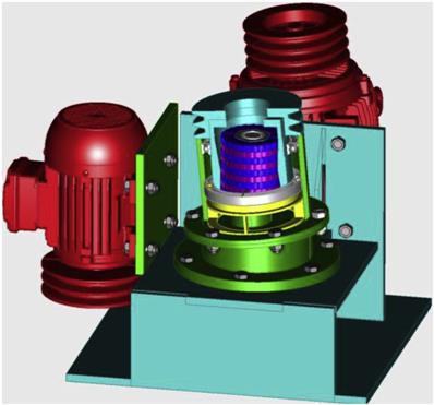
6.4 High Pressure Grinding Rolls
The pressure exerted on the feed particles in conventional roll crushers is in the range 10–30 MPa. During the 1970–80s, work by Prof. Schönert of the Technical University of Clausthal, Germany led to the development of the High-Compression Roller Mill, which utilized forces from 50–150 MPa (Schönert, 1979, 1988; McIvor, 1997). The units are now commonly termed High Pressure Grinding Rolls (HPGR) and employ a fixed and movable roll to crush material. A hydraulic pressure system acts on pistons that press the movable roll against a material bed (density >70% solids by volume) fed to the rolls (Figure 6.17). The roll gap can be adjusted depending on the feed particle size and application.

The first commercial installation began operation in 1985 to grind cement clinker (McIvor, 1997). Since then, HPGR technology has seen wide use in the cement, limestone and diamond industries and has recently been implemented in hard rock metalliferous operations (Morley, 2010). Researchers have noted that the high pressure exerted on the particle bed produces a high proportion of fines and particles with micro-cracks and improved mineral liberation, which can be advantageous for subsequent comminution or metallurgical processes (Esna-Ashari and Kellerwessel, 1988; Clarke and Wills, 1989; Knecht, 1994; Watson and Brooks, 1994; Daniel and Morrell, 2004).
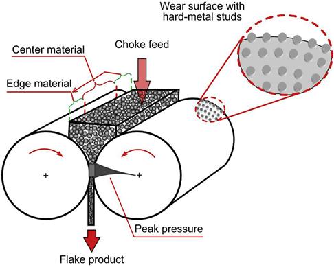
Unlike conventional crushers or tumbling mills, which employ impact and attrition to break particles, the HPGR employs inter-particle crushing in the bed, and as such the particle packing properties of the feed material play a role in determining breakage. Feed that is scalped (fines removed) prior to the HPGR is termed “truncated.” The removal of fines impacts HPGR operation, as coarse particles tend to have a greater impact on roll wear, and the elimination of fines creates a less compact bed, which reduces the inter-particle breakage action. To ensure proper bed, formation the units should be choke fed the entire length of the rolls.
The HPGR product typically comprises fines and portions of compacted cake referred to as “flakes” (Figure 6.18). Depending on flake competency, the product may require subsequent deagglomeration (ranging from a mild pre-soaking to modest attritioning) to release the fines (van der Meer and Grunedken, 2010). It has been shown that the specific energy consumption for compression and ball mill-deagglomeration is considerably less than that of ball mill grinding alone. The typical comminution energy in an HPGR unit is 2.5–3.5 kWh t−1, compared to 15–25 kWh t−1 in ball mill grinding (Brachthauser and Kellerwessel, 1988; Schwechten and Milburn, 1990).

HPGRs were originally designed to be operated with smooth rolls. The HEXADUR® surface is commonly used in cement applications (Figure 6.19). The pre-conditioned surface design incorporates tiles with varying thicknesses, which enhances feed intake. Studded roll surfaces (Figure 6.20) have become standard in the new designs (especially in hard rock applications), because of their improved wear-resistant characteristics. Most surfaces employ an autogenous wear layer, that is, crushed feed material is captured and retained on the roll surface in the interstices between the studs (Figure 6.19(c) and Figure 6.20(b)).


HPGRs can be operated in open- or closed-circuit depending on the application. Closed circuits may employ wet or dry screening or air classification, although classification equipment is not a necessity in certain applications. Due to roll geometry, the press force exerted at the roll edges is less than in the center, resulting in a coarser edge product (Figure 6.21). Splitters can be used to separate the edge product for recycle (van der Meer and Grunedken, 2010). Figure 6.22 shows an example of edge material recycle using a splitter in a crushing application at a copper flotation plant.

6.5 Impact Crushers
Impact crushers (e.g., hammer mills and impact mills) employ sharp blows applied at high speed to free-falling rocks where comminution is by impact rather than compression. The moving parts are “beaters,” which transfer some of their kinetic energy to the ore particles upon contact. Internal stresses created in the particles are often large enough to cause them to shatter. These forces are increased by causing the particles to impact upon an anvil or breaker plate.
There is an important difference between the states of materials crushed by pressure and by impact. There are internal stresses in material broken by pressure that can later cause cracking. Impact causes immediate fracture with no residual stresses. This stress-free condition is particularly valuable in stone used for brick-making, building, and roadmaking, in which binding agents (e.g., tar) are subsequently added. Impact crushers, therefore, have a wider use in the quarrying industry than in the metal-mining industry. They may give trouble-free crushing on ores that tend to be plastic and pack when the crushing forces are applied slowly, as is the case in jaw and gyratory crushers. These types of ore tend to be brittle when the crushing force is applied instantaneously by impact crushers (Lewis et al., 1976).
Impact crushers are also favored in the quarry industry because of the improved product shape. Cone crushers tend to produce more elongated particles because of their ability to pass through the chamber unbroken. In an impact crusher, all particles are subjected to impact and the elongated particles, having a lower strength due to their thinner cross section, would be broken (Ramos et al., 1994; Kojovic and Bearman, 1997).
6.5.1 Hammer Mills
Figure 6.23(a) shows the cross section of a typical hammer mill. The hammers (Figure 6.23(b)) are made from manganese steel or nodular cast iron containing chromium carbide, which is extremely abrasion resistant. The breaker plates are made of the same material.

The hammers are pivoted so as to move out of the path of oversize material (or tramp metal) entering the crushing chamber. Pivoted (swing) hammers exert less force than they would if rigidly attached, so they tend to be used on smaller impact crushers or for crushing soft material. The exit from the mill is perforated, so that material that is not broken to the required size is retained and swept up again by the rotor for further impacting. There may also be an exit chute for oversize material which is swept past the screen bars. Certain design configurations include a central discharge chute (an opening in the screen) and others exclude the screen, depending on the application.
The hammer mill is designed to give the particles velocities of the order of that of the hammers. Fracture is either due to impact with the hammers or to the subsequent impact with the casing or grid. Since the particles are given high velocities, much of the size reduction is by attrition (i.e., particle on particle breakage), and this leads to little control on product size and a much higher proportion of fines than with compressive crushers.
The hammers can weigh over 100 kg and can work on feed up to 20 cm. The speed of the rotor varies between 500 and 3,000 rpm. Due to the high rate of wear on these machines (wear can be taken up by moving the hammers on the pins) they are limited in use to relatively non-abrasive materials. They have extensive use in limestone quarrying and in the crushing of coal. A great advantage in quarrying is the fact that they produce a relatively cubic product.
A model of the swing hammer mill has been developed for coal applications (Shi et al., 2003). The model is able to predict the product size distribution and power draw for given hammer mill configurations (breaker gap, under-screen orientation, screen aperture) and operating conditions (feed rate, feed size distribution, and breakage characteristics).
6.5.2 Impact Mills
For coarser crushing, the fixed hammer impact mill is often used (Figure 6.24). In these machines the material falls tangentially onto a rotor, running at 250–500 rpm, receiving a glancing impulse, which sends it spinning toward the impact plates. The velocity imparted is deliberately restricted to a fraction of the velocity of the rotor to avoid high stress and probable failure of the rotor bearings.

The fractured pieces that can pass between the clearances of the rotor and breaker plate enter a second chamber created by another breaker plate, where the clearance is smaller, and then into a third smaller chamber. The grinding path is designed to reduce flakiness and to produce cubic particles. The impact plates are reversible to even out wear, and can easily be removed and replaced.
The impact mill gives better control of product size than does the hammer mill, since there is less attrition. The product shape is more easily controlled and energy is saved by the removal of particles once they have reached the size required.
Large impact crushers will reduce 1.5 m top size ROM ore to 20 cm, at capacities of around 1500 t h−1, although units with capacities of 3000 t h−1 have been manufactured. Since they depend on high velocities for crushing, wear is greater than for jaw or gyratory crushers. Hence impact crushers are not recommended for use on ores containing over 15% silica (Lewis et al., 1976). However, they are a good choice for primary crushing when high reduction ratios are required (the ratio can be as high as 40:1) and the ore is relatively non-abrasive.
6.5.3 Vertical Shaft Impact (VSI) Crushers
Barmac Vertical Shaft Impact Crusher
Developed in New Zealand in the late 1960s, over the years it has been marketed by several companies (Tidco, Svedala, Allis Engineering, and now Metso) under various names (e.g., duopactor). The crusher is finding application in the concrete industry (Rodriguez, 1990). The mill combines impact crushing, high-intensity grinding, and multi-particle pulverizing, and as such, is best suited in the tertiary crushing or primary grinding stage, producing products in the 0.06–12 mm size range. It can handle feeds of up to 650 t h−1 at a top size of over 50 mm. Figure 6.22 shows a Barmac in a circuit; Figure 6.25 is a cross-section and illustration of the crushing action.

The basic comminution principle employed involves acceleration of particles within a special ore-lined rotor revolving at high speed. A portion of the feed enters the rotor, while the remainder cascades to the crushing chamber. Breakage commences when rock enters the rotor, and is thrown centrifugally, achieving exit velocities up to 90 m s−1. The rotor continuously discharges into a highly turbulent particle “cloud” contained within the crushing chamber, where reduction occurs primarily by rock-on-rock impact, attrition, and abrasion.
Canica Vertical Shaft Impact Crusher
This crusher developed by Jaques (now Terex® Mineral Processing Solutions) has several internal chamber configurations available depending on the abrasiveness of the ore. Examples include the Rock on Rock, Rock on Anvil and Shoe and Anvil configurations (Figure 6.26). These units typically operate with 5 to 6 steel impellers or hammers, with a ring of thin anvils. Rock is hit or accelerated to impact on the anvils, after which the broken fragments freefall into the discharge chute and onto a product conveyor belt. This impact size reduction process was modeled by Kojovic (1996) and Djordjevic et al. (2003) using rotor dimensions and speed, and rock breakage characteristics measured in the laboratory. The model was also extended to the Barmac crushers (Napier-Munn et al., 1996).

6.6 Rotary Breakers
Where large tonnages of coal are treated, the rotary coal breaker (commonly termed the Bradford breaker) can be used (Figure 6.27(a)). This is similar to the cylindrical trommel screen (Chapter 8), consisting of a cylinder 1.8–4.5 m in diameter and length of about 1½ to 2½ times the diameter, revolving at a speed of about 10–18 rpm. The machine is massively constructed, with perforated walls, the size of the perforations being the size to which the coal is to be broken. The ROM coal is fed into the rotating cylinder, at up to 1,500 t h−1 in the larger machines. The machine utilizes differential breakage, the coal being much more friable than the associated stones and shales, and trash such as wood or steel from the mine. The resulting small particles of coal fall through the holes, while the larger lumps of coal are transported by longitudinal lifters (Figure 6.27(b)) within the cylinder until they reach a point where they slide off the lifters and fall to the bottom of the cylinder, breaking by their own impact, and fall through the holes. The lifters are inclined to give the coal a forward motion through the breaker. Shale and stone do not break as easily, and are usually discharged from the end of the breaker, which thus cleans the coal to a certain degree and, as the broken coal is quickly removed from the breaker, produces few coal fines. Although the rotary breaker is an expensive piece of equipment, maintenance costs are low, and it produces positive control of top size product.

Esterle et al. (1996) reviewed the work on modeling of rotary breakers. The work was based at three open pit coal mines in Central Queensland, Australia, where 3 m diameter breakers were handling ROM coal.
6.7 Crushing Circuits and Control
Efforts continue to improve crusher energy efficiency and to reduce capital and operating costs. Larger crushers have been constructed, and in-pit crushing units have been used, which allow relatively cheap ore transportation by conveyor belts, rather than by trucks, to a fixed crushing station (Griesshaber, 1983; Frizzel, 1985; Utley, 2009). The in-pit units are either fixed plants at the pit edge or semi- or fully-mobile units in the pit. A mobile crusher is a completely self-contained unit, mounted on a frame that is moved by means of a transport mechanism either in the open pit as mining progresses or through different mineral processing plants as required. Depending on the crusher size, the mobile unit can be used to support primary or secondary crushing stages or to process the critical size pebbles from a SAG mill. Semi-mobile units can include gyratories, being the crusher of choice for throughputs over 2,500 t h−1. Fully-mobile units typically use jaw, hammer, or roll crushers, fed directly or by apron feeders, at rates of up to 1,000 t h−1.
Crushing plants may be housed with the rest of the milling plant but today are often a separate facility, one reason being to better control dust. Two possible flowsheets were illustrated in Figure 6.1 to provide feed to rod (or ball mill) or to an AG/SAG mill. In some cases, the crushing circuit is designed not only to produce mill feed, but also to provide media for autogenous grinding (Wills, 1983). Crushing plants are characterized by extensive use of conveyors and the energy for transport is a consideration in selecting the type of circuit.
Two possible flowsheets for a crushing plant producing ball mill feed are shown in Figure 6.28. The circuit in Figure 6.28(a) is a “conventional” design and is typical in that the secondary feed is scalped and the secondary product is screened and conveyed to a storage bin, rather than feeding the tertiary crushers directly. The intermediate bins allow good mixing of the secondary screen oversize with the circulating load, and regulation of the tertiary crusher feed, providing more efficient crushing. Note the tertiary circuit is an example of crushers operating in parallel. The circuit is adaptable to automatic feed control to maintain maximum power utilization (Mollick, 1980). Figure 6.28(b) shows a circuit including an HPGR stage. Rosario et al. (2009) provide a selection of possible crushing circuits that plant designers can contemplate.

Advances in instrumentation and process control hardware have made the implementation of computer control more common in crushing circuits. Instrumentation includes ore level detectors, oil flow sensors, power measurement devices, belt scales, variable speed belt drives and feeders, blocked chute detectors, and particle size measurement devices (Horst and Enochs, 1980; Flintoff et al., 2014). An early example of the importance of automatic control is the crushing plant at Mount Isa in Australia, where the output increased by over 15% after controls were introduced (Manlapig and Watsford, 1983).
Supervisory control systems are not usually applied to primary crushers, the instrumentation basically being used to protect them. Thus lubrication flow indicators and bearing temperature detectors may be fitted, together with high and low level alarms in the chamber under the crusher. Vision systems are increasingly being used on both the feed and discharge of primary crushers to guide when changes in the discharge setting are required. Additionally, various systems, including vision, are being explored to detect metal (steel bars, etc.) in the truck dump to the crushers. Steel can tear a conveyor belt leading to downtime and often is undetected as it is hidden beneath ore on the conveyor after the crusher.
The operating and process control objectives for secondary and tertiary crushing circuits differ from one plant to the next. Typically, the main objective is to maximize crusher throughput at some specified product size which often requires ensuring, as best as possible, choke feed in the crusher and a properly selected closed side setting. Due to an increase in power cost and availability at a number of operations, the efficient use of power is becoming a more dominant issue. Numerous variables affect the performance of a crusher, but only three—ore feed rate, crusher set, and, in some cases, feed size—can be adjusted (with the exception of a water flush crusher or HPGR where additional degrees of freedom exist).
Lynch (1977) has described case studies of automatic control systems for various applications. When the purpose of the crushing plant is to produce feed for the grinding circuit, the most important objective of the control system is to ensure a supply of crushed ore at the rate required by the grinding plant. The fineness of the crusher product is maintained by the selection of screens of the appropriate aperture in the final closed circuit loop.
The most effective way of maximizing throughput is to maintain the highest possible crusher power draw, and this has been used to control many plants. A benefit of automated control is the ability to better regulate the feed to the crusher and therefore lessen the variability of the power draw, enabling the system to run closer to the power limit without fear of an overshoot. This alone can result in increased efficiency of over 2% in increased throughput. There is an optimum closed side setting for crushers operating in closed circuit that provides the highest tonnage of finished screen product for a particular power or circulating load limit, noting that the feed tonnage to the crusher increases at larger closed side settings. The power draw can be maintained by the use of a variable speed belt feeding the crusher, although this is not common due to the control challenges of managing the belt. More common is control of the feeders depositing the ore onto the feed belt from a bin or stockpile. This provides the necessary flexibility while greatly simplifying overall control.
Typical control algorithms are based on supervisory control that manages feed versus the power draw and/or a combination of power draw and level in the crusher bowl. These algorithms incorporate expert systems for overall strategy and model predictive controllers to provide a predictable feed rate. In situations where the size delivered from individual feeders is known, another degree of freedom for control is added, the incorporation of feeder bias and selection. Uneven feed from the bin or stockpile combined with the long time delays inherent in the distance between the feed stock and crusher, reduce the efficacy of traditional control and have driven the industry to embrace more advanced expert, model-based and multivariable control. At the same time, the software and technology for these solutions has become more accessible to the plants, resulting in robust solutions.
Operations under choked conditions also require sensing of upper and lower levels of feed in the crusher by mechanical, nuclear, sonic, vision, or proximity switches. Operation at high power draw (choked conditions) leads to increased fines production, such that if the increased throughput provided by the control system cannot be accommodated by the grinding plant, then the higher average power draw can be used to produce a finer product. In most cases, high throughput increases screen loading, which decreases screening efficiency, particularly for the particles close to the screen aperture size. This has the effect of reducing the effective “cut-size” of the screen, producing a finer product (see also Chapter 8). Thus a possible control scheme during periods of excess closed circuit crushing capacity or reduced throughput requirement is to increase the circulating load by reducing the number of screens used, leading to a finer product. The implementation of this type of control loop requires accurate knowledge of the behavior of the plant under various conditions.
In those circuits where the crushers produce a saleable product (e.g., road-stone quarries), the control objective is usually to maximize the production of certain size fractions from each ton of feed. Since screen efficiency decreases as circulating load increases, producing a finer product size, circulating load can be used to control the product size (Chapter 8). This can be effected by control of the crusher setting using a hydraulic adjustment system (Flavel, 1977, 1978; Anon., 1981).
The required variation in crusher setting can be determined by the use of mathematical models of crusher performance (Lynch, 1977; Napier-Munn et al., 1996), from empirical (historical) data, or by measuring product size on-line. Image processing based systems for the continuous measurement of fragmentation size for use throughout the crushing circuit have been in use in the mining industry since the mid-1990s and have now become best practice (Chapter 4). These systems measure, on a real time basis, the size of the ore on a belt or a feeder. Currently four systems are in use: PRC from Portage Technologies Inc., Split-Online from Split Engineering, WipFrag from WipWare Inc., and VisoRock from Metso. An example of the screen capture from a moving conveyor belt is shown in Figure 6.29 (see also Chapter 4).

Additional loops are normally required in crushing circuits to control levels in surge bins between different stages. For instance, the crusher product surge bins can be monitored such that at high level feed is increased to draw down the bins.
The importance of primary crusher control on SAG mill performance at Highland Valley Copper was well recognized, and through the use of image analysis, HVC was able to quantify the effect, and thereby regulate crusher product size through a combination of feed rate and setting control (Dance, 2001). Figure 6.30 illustrates the effect of primary crusher product size on the SAG mill throughput. Tracking the crusher product through the stockpile network, as the amount of medium size material (50–125 mm) increased, the amount of this material in the feed to the SAG mill increased, as measured 24 hours later (the +24 hours key in the figure). This size material constitutes SAG mill critical size in this operation and, as expected, as the amount fed to the SAG mill increased the tonnage decreased, for one of the SAG mills from 2,000 to 1,800 t h−1. This change in amount of medium size material was caused by an increase in the amount in the feed to the primary crusher, resulting from a period of higher energy blasting, which reduced the amount of + 125 mm. Because in this operation the medium size material passed through the crusher virtually unchanged, the increase was reflected in the crusher product. It is necessary to understand these interacting factors to effect control and maximize the throughput of the circuit.
