
Magnetic and Electrical Separation
Magnetic and electrical separators are being considered in the same chapter, as there is often an overlap in the application of the two processes. A classic example of this is the processing of heavy mineral sands in which both magnetic and electrostatic separation are crucial to achieve separation.
Keywords
Magnetic separation; principles; machine types; low-intensity; high-intensity; high-gradient; superconducting; electrostatic separation; charging mechanisms; example flowsheets
13.1 Introduction
Magnetic and electrical separators are being considered in the same chapter, as there is often an overlap in the application of the two processes. A classic example of this is the processing of heavy mineral sands in which both magnetic and electrostatic separation are crucial to achieve separation.
13.2 Magnetism in Minerals
Magnetic separators exploit the difference in magnetic properties between the minerals in a deposit and are used to concentrate a valuable mineral that is magnetic (e.g., magnetite from quartz), to remove magnetic contaminants, or to separate mixtures of magnetic and nonmagnetic valuable minerals. An example of the latter is the tin-bearing mineral cassiterite, which is often associated with traces of the valuable minerals magnetite or wolframite, which can be removed by magnetic separators.
This text will only briefly introduce the concepts associated with magnetism in mineral separation. For those interested in further details there are a number of other sources (Jiles, 1990; Oberteuffer, 1974; Svoboda, 1987; Svoboda and Fujita, 2003).
All materials are affected in some way when placed in a magnetic field, although with many substances the effect is too slight to be easily detected. For the purposes of mineral processing, materials may be classified into two broad groups, according to whether they are attracted or repelled by a magnet:
1. Diamagnetic materials are repelled along the lines of magnetic force to a point where the field intensity is smaller. The forces involved here are very small and diamagnetic substances are often referred to as “nonmagnetic”, although this is not strictly correct. Diamagnetic minerals will report to the nonmagnetic product (“non-mags”) of a magnetic separator as they do not experience a magnetic attractive force.
2. Paramagnetic materials are attracted along the lines of magnetic force to points of greater field intensity. Paramagnetic materials report to the “magnetic” product (“mags”) of a magnetic separator due to attractive magnetic forces. Examples of paramagnetic minerals which are separated in commercial magnetic separators are ilmenite (FeTiO3), rutile (TiO2), wolframite ((Fe, Mn)WO4), monazite ((Ce, La, Nd, Th)PO4), xenotime (YPO4), siderite (FeCO3), chromite (FeCr2O4), and manganese minerals.
Paramagnetism in a material originates due to the presence of unpaired electrons which create magnetic dipoles. When these magnetic dipoles are aligned by an externally applied magnetic field, the resultant magnetic moment causes the material to become magnetized and experience a magnetic force along the lines of the applied magnetic field. Certain elements have electron configurations with many unpaired electrons, but the magnetic response of a given mineral depends on the structure of the mineral as well as its constituent atoms. For example, pyrite (FeS2) is very slightly paramagnetic, but the chemically similar pyrrhotite (Fe1−xS) in the monoclinic structural form is actually strongly magnetic, referred to as ferromagnetic.
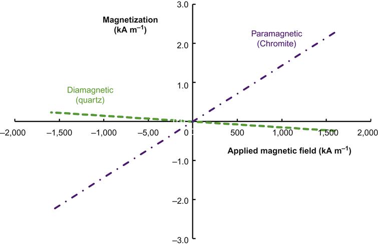
Ferromagnetism can be regarded as a special case of paramagnetism in which the magnetic dipoles of a material undergo exchange coupling so that they can more rapidly align themselves with an applied magnetic field. Examples of diamagnetic, paramagnetic, and ferromagnetic behavior are shown in Figures 13.1 and 13.2 represented as magnetization (density of magnetic dipoles) versus applied magnetic field strength. The slope of these curves represents the dimensionless magnetic susceptibility of the material. Figure 13.1 shows the paramagnetic susceptibility (shown by a positive linear slope) of chromite and the diamagnetic susceptibility (negative linear slope) of quartz, while Figure 13.2 shows the ferromagnetic trend of magnetite. Thanks to exchange coupling, ferromagnetic materials will have very high initial susceptibility to magnetic forces until all of the exchange coupled magnetic moments have aligned with the applied magnetic force. This results in a rapidly decreasing value of susceptibility with increased applied magnetic field (Figure 13.2, points 1–3). Once this alignment has occurred the material is said to have reached its saturation magnetization (a characteristic value of the material shown in Figure 13.2 as a plateau in magnetization), and any further increase in applied magnetic field will not be accompanied by a further increase in magnetization.

Compared to paramagnetic materials, which need high-intensity (high magnetic field) magnetic separators to report to the magnetic product, ferromagnetic materials are recovered in low-intensity magnetic separators.
Measuring Magnetic Properties
The magnetic properties of a material may be measured directly via a vibrating sample magnetometer (used to obtain the data for Figures 13.1 and 13.2) which is specifically designed to capture the variation of the magnetic properties of a material as a function of applied magnetic field strength. Empirical data for paramagnetic mineral samples often includes both paramagnetic and ferromagnetic characteristics due to the presence of impurities in the sample, as mineral grains, or in the mineral’s crystal structure. Similarly, measurements of a predominantly diamagnetic sample may show signs of a paramagnetic impurity. In Figure 13.3, the results are shown for the samples from Figure 13.1 prior to data processing to isolate the paramagnetic or diamagnetic trend.

Vibrating sample magnetometers are expensive instruments and require specialized personnel to operate. As such, they are typically found only in research settings, such as universities. A more practical tool in mineral processing labs for determining magnetic properties is the Frantz Isodynamic Separator, shown diagrammatically in Figure 13.4. In the Frantz separator, mineral particles are fed down a vibrating chute inclined at an angle θ2 which is also inclined in the transverse direction at an angle θ1. The force of gravity is opposed by the magnetic force generated by the electromagnetic coil through which the chute passes. The Frantz is referred to as an isodynamic separator due to the fact that the magnetic force felt by a particle of constant magnetic susceptibility and orientation remains constant throughout the length of the separator (McAndrew, 1957). When the attractive magnetic force is stronger than the force of gravity on a mineral particle it will report to the chute on the right side of Figure 13.4, and when the magnetic force is insufficient to overcome gravity the mineral particle exits the separator on the left side of the chute. As the current through the electromagnetic coil and both θ1 and θ2 may be varied across a wide range, this separator is able to separate minerals of varying magnetic properties. It may even be used to concentrate diamagnetic minerals, in which case the side slope is moved past horizontal such that the chute exit on the right of Figure 13.4 becomes the down slope exit for particles where the diamagnetic force (repulsive magnetic force) is insufficient to overcome the force of gravity. The Frantz may also be used to determine the magnetic susceptibility of a given mineral, provided other materials of known susceptibility are available for proper calibration (McAndrew, 1957). Normally operated dry, it can be modified to operate wet (Todd and Finch, 1984).

The Franz is also used to characterize materials, separating fractions that can then be identified. These data can form the basis of predicting separation in full size magnetic separators. For ferromagnetic materials, the Davis tube is more suitable and is the common tool for characterizing magnetic iron ores (Davis, 1921).
13.3 Equations of Magnetism
The magnetic flux density or magnetic induction is the number of lines of force passing through a unit area of material, B. The unit of magnetic induction is the tesla (T).
The magnetizing force, which induces the lines of force through a material, is called the field intensity, H (or H-field), and by convention has the units ampere per meter (A m−1) (Bennett et al., 1978).
The intensity of magnetization or the magnetization (M, A m−1) of a material relates to the magnetization induced in the material and can also be thought of as the volumetric density of induced magnetic dipoles in the material. The magnetic induction, B, field intensity, H, and magnetization, M, are related by the equation:
(13.1)
where μ0 is the permeability of free space and has the value of 4π×10−7 N A−2. In a vacuum, M=0, and M is extremely low in air and water, such that for mineral processing purposes Eq. (13.1) may be simplified to:
(13.2)
so that the value of the field intensity, H, is directly proportional to the value of induced flux density, B (or B-field), and the term “magnetic field intensity” is then often loosely used for both the H-field and the B-field. However, when dealing with the magnetic field inside materials, particularly ferromagnetic materials that concentrate the lines of force, the value of the induced flux density will be much higher than the field intensity. This relationship is used in high-gradient magnetic separation (discussed further in Section 13.4.1). For clarity it must be specified which field is being referred to.
Magnetic susceptibility (χ) is the ratio of the intensity of magnetization produced in the material over the applied magnetic field that produces the magnetization:
(13.3)
Combining Eqs. (13.1) and (13.3) we get:
(13.4)
If we then define the dimensionless relative permeability, μ, as:
(13.5)
we can combine Eqs. (13.4) and (13.5) to yield:
(13.6)
For paramagnetic materials, χ is a small positive constant, and for diamagnetic materials it is a much smaller negative constant. As examples, from Figure 13.1 the slope representing the magnetic susceptibility of the material, χ, is about 0.001 for chromite and −0.0001 for quartz.
The magnetic susceptibility of a ferromagnetic material is dependent on the magnetic field, decreasing with field strength as the material becomes saturated. Figure 13.2 shows a plot of M versus H for magnetite, showing that at an applied field of 80 kA m−1, or 0.1 T, the magnetic susceptibility is about 1.7, and saturation occurs at an applied magnetic field strength of about 500 kA m−1 or 0.63 T. Many high-intensity magnetic separators use iron cores and frames to produce the desired magnetic flux concentrations and field strengths. Iron saturates magnetically at about 2–2.5 T, and its nonlinear ferromagnetic relationship between inducing field strength and magnetization intensity necessitates the use of very large currents in the energizing coils, sometimes up to hundreds of amperes.
The magnetic force felt by a mineral particle is dependent not only on the value of the field intensity, but also on the field gradient (the rate at which the field intensity increases across the particle toward the magnet surface). As paramagnetic minerals have higher (relative) magnetic permeabilities than the surrounding media, usually air or water, they concentrate the lines of force of an external magnetic field. The higher the magnetic susceptibility, the higher the induced field density in the particle and the greater is the attraction up the field gradient toward increasing field strength. Diamagnetic minerals have lower magnetic susceptibility than their surrounding medium and hence expel the lines of force of the external field. This causes their expulsion down the gradient of the field in the direction of the decreasing field strength.
The equation for the magnetic force on a particle in a magnetic separator depends on the magnetic susceptibility of the particle and fluid medium, the applied magnetic field and the magnetic field gradient. This equation, when considered in only the x-direction, may be expressed as (Oberteuffer, 1974):
(13.7)
where Fx is the magnetic force on the particle (N), V the particle volume (m3), χp the magnetic susceptibility of the particle, χm the magnetic susceptibility of the fluid medium, H the applied magnetic field strength (A m−1), and dB/dx the magnetic field gradient (T m−1=N A−1 m−2). The product of H and dB/dx is sometimes referred to as the “force factor.”
Production of a high field gradient as well as high intensity is therefore an important aspect of separator design. To generate a given attractive force, there are an infinite number of combinations of field and gradient which will give the same effect. Another important factor is the particle size, as the magnetic force experienced by a particle must compete with various other forces such as hydrodynamic drag (in wet magnetic separations) and the force of gravity. In one example, considering only these two competing forces, Oberteuffer (1974) has shown that the range of particle size where the magnetic force predominates is from about 5 μm to 1 mm.
13.4 Magnetic Separator Design
13.4.1 Magnetic Field Gradient
Certain elements of design are incorporated in all magnetic separators, whether they are wet or dry separators with low- or high-intensity magnetic fields. The prime requirement is the provision of a high-intensity field in which there is a steep field strength gradient. In a field of uniform magnetic flux, such as in Figure 13.5(a), magnetic particles will orient, but will not move along the lines of flux. The most straightforward method for producing a converging field is by providing a V-shaped pole above a flat pole, as in Figure 13.5(b). The tapering of the upper pole concentrates the magnetic flux into a very small area, giving high intensity. The lower flat pole has the same total magnetic flux distributed over a larger area. Thus, there is a steep field gradient across the gap by virtue of the different field intensity levels. Another method of producing a high field gradient is by using a pole which is constructed of alternating magnetic and nonmagnetic laminations (Figure 13.6).


The design of field gradient in magnetic separators may be divided into two types: open-gradient magnetic separators (OGMSs) and high-gradient magnetic separators (HGMSs). In an OGMS design, the magnetic gradient is created by the poles of the magnets themselves, and as a result the gradient is relatively weak (Kopp, 1991). These type of separators include free-fall separators and drum separators where particles passing by the separator are deflected into different streams based on their magnetic properties (Kopp, 1991). In HGMS, a ferromagnetic matrix element is introduced into the applied magnetic field to create many points of high field gradient with the intention of capturing the magnetic particles and allowing nonmagnetic particles to flow through the separator.
The introduction of particles with high magnetic susceptibility into a magnetic field will concentrate the lines of force so that they pass through the particles themselves (Figure 13.7). Since the lines of force converge to the particles, a high field gradient is produced, which causes the particles themselves to behave as magnets, thus attracting each other. Flocculation, or agglomeration, of the particles can occur if they are small and highly susceptible and if the field is intense. This is important as these magnetic “flocs” can entrain gangue mineral particles as well as bridge the gaps between magnetic poles, reducing the efficiency of separation.

Much of the optimization of high-intensity separators is based on providing as many sites of high field gradient as possible to improve the magnetic particle carrying capacity of the separator. Wet high-intensity magnetic separators (WHIMSs) will often use a ferromagnetic matrix material to achieve this, such as those shown in Figure 13.8. The recently developed Outotec SLon vertically pulsating high-gradient magnetic separator (VPHGMS) offers improvements in magnetic matrix design via the use of steel rods.

A visual comparison of the effects of different matrix materials on magnetic flux may be seen in Figure 13.9. The design of the matrix can be further optimized by tapering the size and spacing of the rods throughout the matrix (Figure 13.10) so that coarse magnetic particles are trapped first near the slurry inlet, with additional points of high field gradient introduced further along the direction of slurry flow to capture finer magnetic particles (Novotny, 2014). Further details on WHIMS and VPHGMS may be found in Sections 13.5.2 and 13.5.3, respectively.


13.4.2 Magnetic Field Intensity
Provision must be incorporated in the separator for regulating the intensity of the magnetic field in order to deal with various types of material. This is easily achieved in electromagnetic separators by varying the current, while with permanent magnets the interpole distance can be varied. In the case of laboratory separators, this can also be achieved by interchanging the permanent magnets for magnets of higher magnetic field intensity. A special class of magnetic separators, known as superconducting separators, may be used when very high field intensities are required. Additional information on superconducting separators may be found in Section 13.5.4.
It is important to note that increasing field intensity does not necessarily lead to an improved separation. Work by Svoboda (1994) with HGMS has shown that the magnetic field strength should be carefully selected according to the application, as higher field strengths may lead to increased capture of weakly magnetic gangue particles. The field should be sufficient to ensure that a particle which collides with a matrix element will remain fixed to that element; any further increase serves only to retain particles with weaker magnetic properties. Another negative impact of high field strength is that for particles exhibiting some degree of magnetic ordering, a relatively common situation in mineral processing, increased field strength actually serves to decrease the magnetic susceptibility (Svoboda, 1994). Work by Shao et al. (1996) to measure the magnetic susceptibility of iron minerals at varying field strengths showed that from 0.4 to 0.9 T the susceptibility of a hematite sample decreased by more than 50%. A similar result is seen in Figure 13.2, where the susceptibility of magnetite decreases from 1.7 to 0.1 as the applied magnetic field strength is increased from 0.1 to 0.4 T (80–320 kA m−1). While such a decrease in magnetic susceptibility is significant, it must be considered in the context of the increasing applied magnetic field strength, as both H and χ affect the force experienced by a mineral particle (Eq. (13.7)). The product of the two, χH, should be calculated to capture the effect of both the decreasing magnetic susceptibility and the increasing applied magnetic field strength. An example of such a calculation for the mineral from Figure 13.2 is given in Table 13.1.
Table 13.1
Comparison of Product of Magnetic Susceptibility and Applied Magnetic Field Between Points Along the Curve in Figure 13.2
| Point | Applied Magnetic Field (kA m−1) | χH (kA m−1) |
| 1 | 80 | 134 |
| 2 | 160 | 49 |
| 3 | 320 | 23 |
As magnetic field strength is increased, the magnetic field gradient in the separator will also change; this is not considered in the calculations in Table 13.1, although it will have a direct effect on the force experienced by the mineral particles. Excess applied field strength may actually decrease the field gradient in a given separator (Section 13.4.1) (Svoboda, 1994). Since the magnetic force on a particle is directly proportional to the magnetic susceptibility of the particle as well as the magnetic field gradient in the separator, as seen in Eq. (13.7), the net effect of increased field strength can actually be a decrease in the magnetic force experienced by the particle. It is therefore crucial that the appropriate magnetic field is applied for a given separation.
13.4.3 Material Transport in Magnetic Separators
Commercial magnetic separators are continuous-process machines, and separation is carried out on a moving stream of particles passing into and through the magnetic field. Close control of the speed of passage of the particles through the field is essential, which typically rules out free fall as a means of feeding. Belts or drums are very often used to transport the feed through the field.
As discussed in Section 13.4.1, flocculation of magnetic particles is a concern in magnetic separators, especially with dry separators processing fine material. If the ore can be fed through the field in a monolayer, this effect is much less serious, but, of course, the capacity of the machine is drastically reduced. Flocculation is often minimized by passing the material through consecutive magnetic fields, which are usually arranged with successive reversals of the polarity. This causes the particles to turn through 180°, each reversal tending to free the entrained gangue particles. The main disadvantage of this method is that flux tends to leak from pole to pole, reducing the effective field intensity.
Provision for collection of the magnetic and nonmagnetic fractions must be incorporated into the design of the separator. Rather than allow the magnetics to contact the pole-pieces, which then requires their detachment, most separators are designed so that the magnetics are attracted to the pole-pieces, but come into contact with some form of conveying device, which carries them out of the influence of the field, into a bin or a belt. Nonmagnetic disposal presents no problems; free fall from a conveyor into a bin is often used. Middlings are readily produced by using a more intense field after the removal of the highly magnetic fraction.
13.5 Types of Magnetic Separator
Magnetic separators are generally classified into low- and high-intensity machines, but here we include high-gradient and superconducting devices.
13.5.1 Low-Intensity Magnetic Separators
Low-intensity separators are used to treat ferromagnetic materials and some highly paramagnetic minerals.
As shown in Figure 13.2, minerals with ferromagnetic properties have high susceptibility at low applied field strengths and can therefore be concentrated in low intensity (<~0.3 T) magnetic separators. For low-intensity drum separators (Figure 13.11) used in the iron ore industry, the standard field, for a separator with ferrite-based magnets, is 0.12 T at a distance of 50 mm from the drum surface (Novotny, 2014). Work by Murariu and Svoboda (2003) has also shown that such separators have maximum field strengths on the drum surface of less than 0.3 T. The principal ferromagnetic mineral concentrated in mineral processing is magnetite (Fe3O4), although hematite (Fe2O3) and siderite (FeCO3) can be roasted to produce magnetite and hence give good separation in low-intensity machines.

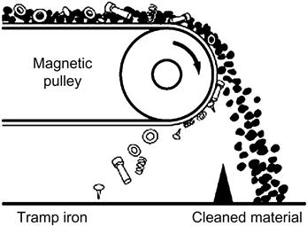
The removal of “tramp“ iron from feed belts can also be regarded as a form of low-intensity magnetic separation. However, tramp iron removal is usually accomplished by means of a magnetic pulley at the end of an ore conveyor (Figure 13.12) or by a guard magnet suspended over the conveyor belt (see Chapter 2). Tramp iron removal is important prior to crushing and in certain cases removal of the iron produced from grinding media wear can be important for downstream processing. A common example of the latter is processing gold ores, where the use of magnetic separation (typically a drum separator) in advance of centrifugal gravity concentration is used to remove tramp iron and prevent damage to the centrifugal separator, as well as avoiding contamination of the gravity concentrate with dense iron particles (Bird and Briggs, 2011).
Dry low-intensity magnetic separation is confined mainly to the concentration of coarse sands which are strongly magnetic, a process known as “cobbing,” and is often carried out using drum separators. For particles below 5 mm, dry separation tends to be replaced by wet methods, which produce less dust loss and usually yield a cleaner product. Low-intensity wet separation is widely used for recycling (and cleaning) magnetic media in dense medium separation (DMS) processes (see Chapter 11) and for the processing of ferromagnetic sands.
The general design of drum separators is a rotating, hollow, nonmagnetic drum containing multiple stationary magnets of alternating polarity. The medium-intensity Permos separator uses many small magnet blocks, whose direction of magnetization changes in small steps. This is said to generate a very even magnetic field, requiring less magnetic material (Wasmuth and Unkelbach, 1991). The spatial arrangement of the magnets within a drum separator may be varied depending on the specific requirements of the application. This is illustrated by the two variants of magnet configuration offered for Metso’s low-intensity drum separator for DMS applications. The two configurations (Figure 13.13) demonstrate the trade-off between increasing magnetic loading capacity (Figure 13.13(a)) to capture more particles and increasing field gradient (Figure 13.13(b)) to capture finer or less susceptible particles. The high-capacity arrangement has fewer, larger poles, which results in a lower field gradient but a higher magnetic flux of 0.12 T at a distance of 50 mm from the roll surface (Metso, 2014a). The high gradient variant has more, smaller poles, resulting in a higher field gradient to better capture fine magnetic particles, but at reduced capacity (magnetic flux of only 0.06 T at a distance of 50 mm from the roll surface) (Metso, 2014a).

Although drum separators initially employed electromagnets, permanent magnets are used in modern devices, utilizing ceramic or rare earth magnetic alloys, which retain their intensity for an indefinite period (Norrgran and Marin, 1994). Separation in a drum separator occurs by the “pick-up“ principle, wherein magnetic particles are lifted by the magnets and pinned to the drum and are conveyed out of the field, leaving the nonmagnetics (usually the gangue) in the tailings compartment. Water is introduced to provide flow, which keeps the pulp in suspension. Field intensities of up to 0.7 T at the pole surfaces can be obtained in this type of separator.
The drum separators shown in Figures 13.11 and 13.14 are of the concurrent type (as shown by the separator tank flow pattern in Figure 13.14), whereby the concentrate is carried forward by the drum and passes through a gap, where it is compressed and dewatered before leaving the separator. This design is most effective for producing a clean magnetic concentrate from relatively coarse feeds (up to 6–8 mm) and is widely used in dense medium recovery systems. In addition to the concurrent arrangement (Figure 13.14), drum separators may also be configured with counter-current and counter-rotation arrangements (Figures 13.15 and 13.16).


In a counter-current separator, the tailings are forced to travel in the opposite direction to the drum rotation and are discharged into the tailings chute. This type of separator is designed for finishing operations on relatively fine material, of particle size less than about 800 μm. Pulp densities in this type of separator are typically lower than in the concurrent configuration.
The third possible configuration is the counter-rotation type, where the feed flows in the opposite direction to the rotation. This type is used in roughing operations, where occasional surges in feed must be handled, and where magnetic material losses are to be held to a minimum when high solids loading is encountered, while an extremely clean concentrate is not required.
Drum separators are widely used to treat low-grade iron ores, which contain 40–50% Fe, mainly as magnetite, but in some areas with hematite, finely disseminated in bands in hard siliceous rocks. Very fine grinding is necessary to free the iron minerals that produce a concentrate requiring pelletizing before being fed to steelmaking blast furnaces.
At the Iron Ore Company of Canada’s Carol Project, low-intensity magnetic separation is used as an initial cobbing step on the cyclone overflow of the ball mill discharge to remove magnetite. This magnetite concentrate is then combined with the tailings of spiral gravity concentrators to be fed to a rougher wet drum low-intensity separator where magnetite is removed and sent directly to the pellet plant, with the tailings from the drum being sent for further gravity processing to concentrate any remaining hematite (Damjanović and Goode, 2000).
The mechanism by which ferromagnetic particles are captured by low-intensity drum separators has been investigated for both high solids content (10–17% solids by weight) and low solids content (2%) (Rayner and Napier-Munn, 2000). For the high feed solids case, magnetic recovery occurs primarily via the formation of magnetic flocs, which are then captured. At lower feed solids, magnetic capture is not contingent on floc formation, as the increased distances between particles make it more difficult for flocs to form. These findings are significant as they provide information on the dominant variable affecting ferromagnetic losses to the tailings. At high feed solids content, particles with low magnetic susceptibility are lost to the tailings (higher magnetic susceptibility promotes floc formation), while at low feed solids content tailings losses are primarily fine ferromagnetic particles (Rayner and Napier-Munn, 2000).
At Palabora, the tailings from copper flotation (see Section 12.17.1) are deslimed, after which the +105 μm material is treated by wet low-intensity drum separators to recover 95% of the magnetite at a grade of 62% Fe.
Another example of wet low-intensity magnetic separation is the treatment of flotation tailings at the Niobec mine in Quebec, Canada (Section 12.17.7). The Niobec mine employs multiple flotation stages to produce a pyrochlore concentrate including carbonate, pyrochlore, and sulfide flotation circuits. The deslimed tails from the carbonate flotation bank are fed to low-intensity drum magnetic separators to remove approximately 1 t h−1 of magnetite assaying 68.30% Fe, 0.08% Nb2O5, 0.80% SiO2, and 0.16% P2O5. The nonmagnetic product (containing the bulk of the Nb) is then sent to the pyrochlore flotation circuit for upgrading (Biss and Ayotte, 1989).
The cross-belt separator (Figure 13.17) and disc separators, once widely used in the mineral sands industry, are now considered obsolete. They are being replaced with rare earth roll magnetic separators and rare earth drum magnetic separators (Arvidson, 2001).

Rare earth roll separators use alternate magnetic and nonmagnetic laminations (like those illustrated in Figure 13.6). Feed is carried onto the magnetic roll by a belt as shown in Figure 13.18 to limit bouncing or scattering of particles and to ensure they all enter the magnetic zone with the same horizontal velocity. In a rare earth roll separator, the variables affecting separation are the magnetic field strength, the feed rate, the linear speed of the roll surface, and the particle size of the material (Eriez, 2003). Most importantly, the centrifugal force applied to the mineral particles by the roll surface must be optimized to achieve a sharp separation (Eriez, 2003). To control the centrifugal force, roll speed can be adjusted over a wide range, allowing the product quality to be “dialed in.”

Dry rare earth drum separators provide a “fan” of separated particles, which can often be seen as distinct streams (Figure 13.18). The fan can be separated into various grades of magnetic product and a nonmagnetic tailing. In some mineral sands applications, drum separators have been integrated with one or more rare earth rolls, arranged to treat the middlings particles from the drum. In any dry magnetic separator, the careful control of feed moisture is critical to avoid smaller particles sticking to larger particles (Oberteuffer, 1974). While increasing particle size increases the acceptable moisture limits, even at a particle size of 90% passing 20 mm, the recommended moisture limit for Metso’s dry drum separators is only 3% (Metso, 2014b).
13.5.2 High-Intensity Magnetic Separators
Weakly paramagnetic minerals can only be effectively recovered using high-intensity (B-fields of 2 T or greater) magnetic separators (Svoboda, 1994). Until the 1960s, high-intensity separation was confined solely to dry ore, having been used commercially since about 1908. This is no longer the case, as many new technologies have been developed to treat slurried feeds.
Induced roll magnetic (IRM) separators (Figure 13.19) are widely used to treat beach sands, wolframite and tin ores, glass sands, and phosphate rock. They have also been used to treat weakly magnetic iron ores, principally in Europe. The roll, onto which the ore is fed, is composed of phosphated steel laminates compressed together on a nonmagnetic stainless steel shaft. By using two sizes of laminations, differing slightly in outer diameter, the roll is given a serrated profile, which promotes the high field intensity and gradient required. Field strengths of up to 2.2 T are attainable in the gap between feed pole and roll. Nonmagnetic particles are thrown off the roll into the tailings compartment, whereas magnetics are held, carried out of the influence of the field and deposited into the magnetics compartment. The gap between the feed pole and rotor is adjustable and is usually decreased from pole to pole (to create a higher effective magnetic field strength) to take off successively more weakly magnetic products.

The primary variables affecting separation using an IRM separator are the magnetic susceptibility of the mineral particles, the applied magnetic field intensity, the size of the particles, and the speed of the roll (Singh et al., 2013). The setting of the splitter plates cutting into the trajectory of the discharged material is also of importance.
In most cases, IRM separators have been replaced by the more recently developed (circa 1980) rare earth drum and roll separators, which are capable of field intensities of up to 0.7 and 2.1 T, respectively (Norrgran and Marin, 1994). The advantages of rare earth roll separators over IRM separators include: lower operating costs due to decreased energy requirements, less weight leading to lower construction and installation costs, higher throughput, fewer required stages, and increased flexibility in roll configuration which allows for improved separation at various size ranges (Dobbins and Sherrell, 2010).
Dry high-intensity separation is largely restricted to ores containing little, if any, material finer than about 75 μm. The effectiveness of separation on such fine material is severely reduced by the effects of air currents, particle–particle adhesion, and particle–rotor adhesion.
Without doubt, the greatest advance in the field of magnetic separation was the development of continuous WHIMSs (Lawver and Hopstock, 1974). These devices have reduced the minimum particle size for efficient magnetic separation compared to dry high-intensity methods. In some flowsheets, expensive drying operations, necessary prior to a dry separation, can be eliminated by using an entirely wet concentration system.
Perhaps the most well-known WHIMS machine is the Jones separator, the design principle of which is utilized in many other types of wet separators found today. The machine has a strong main frame (Figure 13.20(a)) made of structural steel. The magnet yokes are welded to this frame, with the electromagnetic coils enclosed in air-cooled cases. The separation takes place in the plate boxes, which are on the periphery of the one or two rotors attached to the central roller shaft and carried into and out of the magnetic field in a carousel (Figure 13.20(b)). The feed, which is thoroughly mixed slurry, flows through the plate boxes via fitted pipes and launders into the plate boxes (Figure 13.21), which are grooved to concentrate the magnetic field at the tip of the ridges. Feeding is continuous due to the rotation of the plate boxes on the rotors and the feed points are at the leading edges of the magnetic fields (Figure 13.20(b)). Each rotor has two feed points diametrically opposed to one another.


The weakly magnetic particles are held by the plates, whereas the remaining nonmagnetic particle slurry passes through the plate boxes and is collected in a launder. Before leaving the field any entrained nonmagnetics are washed out by low-pressure water and are collected as a middlings product.
When the plate boxes reach a point midway between the two magnetic poles, where the magnetic field is essentially zero, the magnetic particles are washed out using high-pressure scour water sprays operating at up to 5 bar. Field intensities of over 2 T can be produced in these machines, although the applied magnetic field strength should be carefully selected depending on the application (see Section 13.4.2). The production of a 1.5 T field requires electric power consumption in the coils of 16 kW per pole.
There are currently two types of WHIMS machines, one that uses electromagnetic coils to generate the required field strength, the other that employs rare earth permanent magnets. They are used in different applications; the weaker magnetic field strength produced by rare earth permanent magnets may be insufficient to concentrate some weakly paramagnetic minerals. The variables to consider before installing a traditional horizontal carousel WHIMS include: the feed characteristics (slurry density, feed rate, particle size, magnetic susceptibility of the target magnetic mineral), the product requirements (volume of solids to be removed, required grade of products), and the cost of power (Eriez, 2008). From these considerations the design and operation of the separator can be tailored by changing the following: the magnetic field intensity and/or configuration, the speed of the carousel, the setting of the middling splitter, the pressure/volume of wash water, and the type of matrix material (Eriez, 2008). The selection of matrix type has a direct impact on the magnetic field gradient present in the separation chamber. As explained in Section 13.4.2, increasing magnetic field can in some applications actually cause decreased performance of the magnetic separation step and it is for this reason that improvements in the separation of paramagnetic materials focus largely on achieving a high magnetic field gradient. The Eriez model SSS-I WHIMS employs the basic principles of WHIMS with improvements in the matrix material (to generate a high field gradient) as well as the slurry feeding and washing steps (to improve separation efficiency) (Eriez and Gzrinm, 2014). While this separator is referred to as a WHIMS, it is in fact more similar to the SLon VPHGMS mentioned in Sections 13.4.1 and 13.5.3. Further discussion on high-gradient magnetic separation (HGMS) may be found in Section 13.5.3.
Wet high-intensity magnetic separation has its greatest use in the concentration of low-grade iron ores containing hematite, where they are an alternative to flotation or gravity methods. The decision to select magnetic separation for the concentration of hematite from iron ore must balance the relative ease with which hematite may be concentrated in such a separator against the high capital cost of such separators. It has been shown by White (1978) that the capital cost of flotation equipment for concentrating weakly magnetic ore is about 20% that of a Jones separator installation, although flotation operating costs are about three times higher (and may be even higher if water treatment is required). Total cost depends on terms for capital depreciation; over 10 years or longer the high-intensity magnetic separator may be more attractive than flotation.
In addition to recovery of hematite (and other iron oxides such as goethite), wet high-intensity separators are now in operation for a wide range of duties, including removal of magnetic impurities from cassiterite concentrates, removal of fine magnetic material from asbestos, removal of iron oxides and ferrosilicate minerals from industrial minerals such as quartz and clay, concentration of ilmenite, wolframite, and chromite, removal of magnetic impurities from scheelite concentrates, purification of talc, the recovery of non-sulfide molybdenum-bearing minerals from flotation tailings, and the removal of Fe-oxides and Fe–Ti-oxides from zircon and rutile in heavy mineral beach sands (Corrans and Svoboda, 1985; Eriez, 2008). In the PGM-bearing Merensky Reef (South Africa), WHIMS has been used to remove much of the strongly paramagnetic orthopyroxene gangue from the PGM-containing chromite (Corrans and Svoboda, 1985). WHIMS has also been successfully used for the recovery of gold and uranium from cyanidation residues in South Africa (Corrans, 1984). Magnetic separation can be used to recover some of the free gold, and much of the silicate-locked gold, due to the presence of iron impurities and coatings. In the case of uranium leaching, small amounts of iron (from milling) may act as reducing agents and negatively affect the oxidation of U4+ to U6+; treatment via WHIMS can reduce the consumption of oxidizing agents by removing a large portion of this iron prior to leaching (Corrans and Svoboda, 1985).
At the Cliffs–Wabush iron ore mine in Labrador, Canada (Figure 13.22), the cyclone overflow from the tailings of a rougher spiral bank is sent to a magnetic scavenger circuit utilizing both low-intensity drum separation and WHIMS. This circuit employs the low-intensity (0.07 T) drum separators to remove fine magnetite particles lost during the spiral gravity concentration step, followed by a WHIMS step using 100 t h−1 Jones separators which are operated at field strengths of 1 T to concentrate fine hematite. Cleaning of only the gravity tailings by magnetic separation is preferred, as relatively small amounts of magnetic concentrate have to be handled, the bulk of the material being essentially unaffected by the magnetic field. The concentrate produced from this magnetic scavenging step is eventually recombined with the spiral concentrate before feeding to the pelletizing plant (Damjanović and Goode, 2000).
The paramagnetic properties of some sulfide minerals, such as chalcopyrite and marmatite (high Fe form of sphalerite), have been exploited by applying wet high-intensity magnetic separation to augment differential flotation processes (Tawil and Morales, 1985). Testwork showed that a Chilean copper concentrate could be upgraded from 23.8% to 30.2% Cu, at 87% recovery.
13.5.3 High-Gradient Magnetic Separators
As noted in Eq. (13.7), in order to separate paramagnetic minerals of low magnetic susceptibility and/or fine size, high field gradients are required. These are generated by exploiting the ferromagnetic properties of iron to generate a high B-field (induced field) many hundreds of times greater than the applied H-field. This, however, requires that the iron be in the volume where separation takes place. The steel plates in a Jones separator, for example, occupy up to 60% of the process volume. Thus, high-intensity magnetic separators using conventional iron circuits tend to be very massive and heavy in relation to their capacity. A large separator may contain over 200 t of iron to carry the flux, hence capital and installation costs are high.
Instead of using one large convergent field in the gap of a magnetic circuit, as in the Jones separator, in HGMS a solenoid is used to generate a uniform field with a solenoid core, or working volume, filled with a matrix of secondary ferromagnetic poles, such as ball bearings, or wire wool, the latter filling only about 10% of the working volume. Each secondary pole, due to its high permeability, can produce maximum field strengths of 2 T at their surface, but more importantly, each pole produces, in its immediate vicinity, high field gradients of up to 14 T/mm. Thus, a multitude of high gradients across numerous small gaps, centered on each of the secondary poles, is achieved.
The solenoid can be clad externally with an iron frame to form a continuous return path for the magnetic flux, thus reducing the energy consumption for driving the coil by a factor of about 2. The matrix is held in a canister into which the slurry is fed. Both continuous and batch-type HGMS are available, with batch-type HGMS requiring periodic demagnetization in order to remove accumulated magnetic particles, while the continuous HGMS (Figure 13.23) operates in a carousel-type configuration similar to the Jones WHIMS (Metso, 2014c,d).

An inherent disadvantage of high-gradient separators is that in producing an increase in field gradient, the working gap between secondary poles is reduced, so that the magnetic force has a short reach of no more than about 1 mm. It is therefore necessary to use gaps of only about 2 mm between poles, such that the matrix separators are best suited to the treatment of very fine particles. They are used mainly in the kaolin industry for removing iron-containing particles which lower brightness.
In order to address some of the deficiencies in the design of HGMS, new horizontally fed vertical carousel separators have been designed that incorporate a pulsating feed system to ensure particle dispersion (i.e., avoid flocculation) and prevent nonmagnetic entrainment. The SLon VPHGMS (Figures 13.24 and 13.25) employs a unique matrix of steel rods oriented perpendicular to the applied magnetic field (Section 13.4.1) as well as flushing of trapped magnetic particles (Figure 13.26) in the reverse direction to the feed in order to reduce particle momentum, maximize particle trapping, and improve separation (Outotec, 2013). The rod diameter in the matrix may be tailored for the given application to vary the maximum particle size that can pass through the separator from 0.6 up to 3.0 mm (Outotec, 2013). The averaged magnetic field intensity across the entire VPHGMS is no greater than 1.3 T; however, as the steel rod matrix becomes saturated, intensities up to 1.8 T can be achieved at the matrix surface with an applied magnetic field of only 1 T (Outotec, 2013). The SLon separator has been applied in the concentration of fine particles such as hematite and ilmenite, and for desulfurization and dephosporization of iron ore feeds prior to steelmaking (Xiong, 1994, 2004). Eriez also offers a vertical carousel-type WHIMS with similar innovations to the SLon VPHGMS, such as pulsating feed and high capacity due to improved matrix washing (Eriez and Gzrinm, 2014). The recently developed version of the Eriez separator is somewhat confusingly referred to as WHIMS, while using a rod matrix to produce high magnetic field gradients in a manner similar to HGMS (Eriez and Gzrinm, 2014). The Eriez separator has been successfully applied to the following: the concentration of Fe-bearing minerals (hematite, limonite, siderite, chromite), the cleaning of nonferrous ores (quartz, cassiterite, garnet), the recovery of rare earth minerals, and the purification of nonmetallic ores (quartz, feldspar, kaolin, alusite, kyanite) (Eriez and Gzrinm, 2014).


13.5.4 Superconducting Separators
Future developments and applications of magnetic separation in the mineral industry lie in the creation and use of increasingly higher product of field and field gradient, that is, the “force factor.” Matrix separators with very high field gradients and multiple small working gaps can draw little benefit from field strengths above the saturation levels of the secondary poles (~2 T for an iron/steel matrix material). As discussed in Section 13.4.1, the alternative to HGMS is OGMS, where separators with large working volumes deflect coarser particles at high capacity, rather than capture particles, as in HGMS. As the gradient in OGMS is relatively low, these separators need to use the highest possible field strengths to generate the high magnetic forces required to treat weakly paramagnetic particles. Field strengths in excess of 2 T can only be generated economically by the use of superconducting magnets (Kopp, 1991; Watson, 1994).
Certain alloys have the property of presenting no resistance to electric currents at extremely low temperatures. An example is niobium–titanium at 4.2 K, the temperature of liquid helium. Once a current is established through a coil made from a superconducting material, it will continue to flow without being connected to a power source, and the coil will become, in effect, a permanent magnet. Superconducting magnets can produce extremely intense and uniform magnetic fields, of up to 15 T. The main problem, of course, is in maintaining the extremely low temperatures. In 1986, a Ba/La/Cu oxide composite was made superconductive at 35 K, promoting a race to prepare ceramic oxides with much higher superconducting temperatures (Malati, 1990). Unfortunately, these materials are of a highly complex crystal structure, making them difficult to fabricate into wires. They also have a low current-carrying capacity, so it is likely that for the foreseeable future superconducting magnets will be made from ductile niobium alloys, embedded in a copper matrix.
The main advantage of superconducting separators is that elevated magnetic field strength increases the maximum feed slurry velocity with a corresponding increase in capacity (Kopp, 1991). In order to fully utilize this capacity, downtime for removal of accumulated magnetic particles from the working volume of the separator must be minimized through the use of a reciprocating or continuously cycling matrix (Kopp, 1991). Another advantage of these separators is the reduced weight of the separators (smaller coils and windings along with much less iron required compared to the heavy frames and matrix materials used in HGMS) (Gillet and Diot, 1999). The factors limiting the adoption of superconducting separators are the difficulties in maintaining the very low temperatures necessary for the material to retain its superconducting properties against heat leaks, and the high energy costs associated with maintaining this refrigeration (Kopp, 1991). Superconducting magnets are generally only viable when large field volumes and magnetic fields greater than 2 T are required (Kopp, 1991).
In 1986, a superconducting HGMS was designed and built by Eriez Magnetics to remove magnetic (and colored) contaminants from kaolinite clay for operations in the United States. This machine used only about 0.007 kW in producing 5 T of flux, the ancillary equipment needed requiring another 20 kW. In comparison, a conventional 2 T high-gradient separator of similar throughput would need about 250 kW to produce the flux, and at least another 30 kW to cool the magnet windings.
The 5 T machine is an assembly of concentric components (Figure 13.27). A removable processing canister is installed in a processing chamber located at the center of the assembly. This is surrounded by a double-walled, vacuum-insulated container that accommodates the superconductive niobium/titanium–tantalum winding and the liquid helium coolant. A thermal shield, cooled with liquid nitrogen to 77 K, limits radiation into the cryostat. In operation, the supply of slurry is periodically cut off, the magnetic field is shut down, and the canister backwashed with water to clear out accumulated magnetic contaminants.

A picture of a superconducting magnetic separator in a horizontal arrangement installed in a plant is shown in Figure 13.28.

An open-gradient drum magnetic separator with a superconducting magnet system has been operating commercially since the 1980s (Unkelbach and Kellerwessel, 1985; Wasmuth and Unkelbach, 1991). Although separation is identical to that in conventional drum separators, the magnetic flux density at the drum surface can reach over 4 T.
The development of HGMS and superconducting separators capable of concentrating very fine or very weakly magnetic mineral particles has prompted the application of magnetic separation techniques to treat many waste streams from mineral processing operations. Fine (<10 μm), weakly magnetic hematite and limonite have been recovered by a combination of selective flocculation using sodium oleate and kerosene followed by HGMS (Song et al., 2002). HGMS has been used to recover fine gold-bearing leach residues from uranium processing, and fine Pb minerals containing V and Zn from a mining waste dump (Watson and Beharrell, 2006). A single-stage extraction of ilmenite from highly magnetic gangue minerals has been developed using a superconducting HGMS system (the difference in magnetic susceptibility between ilmenite and gangue is only significant at very high magnetic field strength). However, this process is still faced with the typical challenges associated with an industrial installation of a superconducting separator (Watson and Beharrell, 2006). Another interesting, and potentially significant, application of HGMS is in the treatment of wastewater streams containing heavy metal ions. Multiple authors have developed processes where the metal ions to be removed are coprecipitated with Fe ions to form a fine, dispersed magnetite phase which can be easily extracted through the use of HGMS (Gillet et al., 1999; Karapinar, 2003).
13.6 Electrical Separation
Electrical separation exploits the differences in electrical conductivity between different minerals in a feed. Since almost all minerals show some difference in conductivity, it would appear to represent the universal concentrating method. In practice, however, the method has fairly limited applications due to the required processing conditions (notably a perfectly dry feed), and its greatest use is in separating some of the minerals found in heavy mineral sands from beach or stream placer deposits (Dance and Morrison, 1992). Electrical separation also suffers from a similar disadvantage to dry magnetic separation—the capacity is very small for finely divided material. For most efficient operation, the feed to most electrical separators should be in a layer, one particle deep, which reduces the throughput if the particle size is small (<75 μm).
There are two distinct forces which may be considered in the context of electrical separation. The electrophoretic force is the force experienced by a charged particle under the influence of an electric field, and the dielectrophoretic force is the force experienced by a neutral particle in a fluid when subjected to a nonuniform electric field. The dielectrophoretic force is somewhat analogous to magnetic force as it relies on the polarization of a neutral particle into an electric dipole as well as a nonuniform applied field (Lockhart, 1984). The deliberate use of dielectrophoresis is almost nonexistent in mineral processing however, as the electrophoretic force is much stronger (Lockhart, 1984).
In order to exploit the electrophoretic force for mineral separation, a treatment step prior to separation is required in all electrical separators to selectively charge the mineral particles. This selective development of charges on particles relies on conductivity differences between the minerals. As most electrical conduction occurs in the surface layers of atoms (Dance and Morrison, 1992), electrical separation may be thought of as a surface-based separation, similar to flotation, as opposed to magnetic and gravity separation which rely on differences in bulk properties (magnetic susceptibility, specific gravity).
There are three main mechanisms by which minerals are charged: ion bombardment (corona charging), conductive induction, and frictional charging (tribocharging or contact electrification). Each of these three mechanisms has a corresponding separator type, the details of which are described in the following sections. To understand electrical separation methods, knowledge of the electrical properties of materials is required. Introduction to the relevant concepts, as they apply to mineral processing, along with detailed descriptions of many industrial separators, may be found in the comprehensive reviews by Kelly and Spottiswood (1989a–c) and Manouchehri et al. (2000).
13.6.1 Ion Bombardment
Charging via ion bombardment occurs as a high voltage is applied between two electrodes so that the gas near the electrodes ionizes and forms a corona discharge, a continuous flow of gaseous ions. Mineral particles passing through this corona are bombarded with the flow of ions and develop a charge. A similar mechanism of charge application is employed in electrostatic precipitators used to remove fine particulate matter from flowing gas streams. In mineral separation applications, different conductivities of the charged mineral particles then result in different rates of charge decay and correspondingly different forces experienced by the particles.
The typical separator relying on corona charging is the high-tension roll (HTR) separator (Figure 13.29). In this separator the feed, a mixture of ore minerals of varying susceptibilities to surface charging, is fed to a rotating drum made from mild steel, or some other conducting material, which is grounded through its support bearings. An electrode assembly, comprising a brass tube in front of which is supported a length of fine wire, spans the complete length of the roll and is supplied with a fully rectified DC supply of up to 50 kV, usually of negative polarity. Together these two electrodes act to create a dense high-voltage discharge. The fine wire tends to discharge readily, whereas the large electrode tends to have a short range, dense, nondischarging field. This combination creates a strong discharge pattern that may be “beamed” in a definite direction and concentrated to a very narrow arc. The voltage supplied should be such that ionization of the air takes place. Arcing between the electrode and the roll must be avoided, as this destroys the ionization.

When ionization occurs, the mineral particles receive a spray discharge of ions which gives all particles in the corona field a surface charge. As the HTR drum rotates and particles are moved outside of the corona field, weakly conductive particles maintain a high surface charge, causing them to be attracted to and pinned to the rotor surface. This is often referred to as pinning by the image force (Figure 13.30), and it may be explained by the charged mineral particle inducing a charge of opposite sign on the rotor (Dance and Morrison, 1992). Pinned particles are removed from the rotor surface either through the eventual decay of their surface charge or mechanically by means of a brush.

Particles of relatively high conductivity lose their surface charge as the charge rapidly dissipates to the earthed rotor. The centrifugal force of the rotor, along with gravitational and frictional forces, is then able to throw these particles from the roll and away from the relatively low-conductivity particles that remain pinned so that two streams of particles develop which may be collected separately through the use of a splitter. The separation can be optimized by varying the splitter position. However, predicting particle trajectories from an HTR separator is challenging, as Edward et al. (1995) have shown that particles do not instantaneously accelerate to the roll speed, due to slip on the rotor surface.
The primary industrial use of HTR separators is in the processing of heavy mineral sands (Dance and Morrison, 1992). Other uses include coal cleaning (Butcher and Rowson, 1995), and recycling metals from plastic waste (Dascalescu et al., 1993). Table 13.2 shows typical minerals which are either pinned to or thrown from the rotor during HTR separation.
Table 13.2
Typical Conductivity and Behavior of Minerals in a High-Tension Separator
| Nonconductive Minerals (Pinned) | Conductive Minerals (Thrown) |
| Apatite | Cassiterite |
| Barite | Chromite |
| Calcite | Diamond |
| Coal | Feldspar |
| Corundum | Galena |
| Garnet | Gold |
| Gypsum | Hematite |
| Kyanite | Ilmenite |
| Monazite | Limonite |
| Quartz | Magnetite |
| Scheelite | Pyrite |
| Sillimonite | Rutile |
| Spinel | Sphalerite |
| Tourmaline | Stibnite |
| Zircon | Tantalite |
| Wolframite |
A combination of pinning and lifting can be created by using a third “static” electrode following the corona discharge electrodes with a diameter large enough to preclude corona discharge. The conducting particles, which are thrown from the rotor, are attracted to this third electrode, and the combined process produces a very wide and distinct separation between conductive particles (lifted from the rotor surface) and nonconductive particles (pinned to the rotor surface).
High-tension separators operate on feeds containing particle sizes of 60–500 μm. Particle size influences separation behavior, as surface charges on a coarse particle are lower in relation to its mass than on a fine particle. Thus, a coarse particle is more readily thrown from the roll surface, and the conducting fraction (particles thrown from the rotor) often contains a small proportion of coarse nonconductors. Similarly, the finer the particles the more they are influenced by the surface charge, and the nonconducting fraction often contains some fine conducting particles. This cross-contamination may also be interpreted in terms of the interplay between the centrifugal force on a particle and the image force acting to pin a charged particle to a grounded surface. The centrifugal force varies with particle mass, while the image force varies with surface area (as charge is accumulated on the particle surface) so, consequently, the centrifugal force is dominant at coarse particle sizes (Dance and Morrison, 1992; Svoboda, 1993).
Some machine factors affecting the operation of an HTR separator include: geometry of the electrode assembly, electrode voltage and polarity, rotor speed, rotor diameter, and splitter position (Dance and Morrison, 1992). Larger rotor diameters help to increase recovery, while a smaller rotor diameter improves the grade of the conducting fraction (Svoboda, 1993). A similar dependence exists for particle density, rotor speed, and the coefficient of friction between the particle and rotor surface, so that separation selectivity is maximized at low particle density, small rotor diameter, high rotor speed, and high coefficient of friction (Svoboda, 1993). The effect of rotor speed on separation is complex and dependent on the conductivity of a given particle, as the act of increasing rotor speed decreases the time available for charge decay. In this way, increased rotor speed increases the chance that a conductive mineral particle will report to the nonconductor fraction, while high rotor speeds will also increase the centrifugal force on a nonconductive particle so that it is more likely to incorrectly report to the conductive fraction (Svoboda, 1993). Stated another way, increased rotor speed simultaneously increases the minimum particle size necessary for a conductive particle to be thrown from the rotor while decreasing the maximum nonconductive particle size that will be pinned to the rotor (Svoboda, 1993).
While HTR separation primarily exploits the differences in conductivities between minerals, an equally important criteria for successful operation is the presence of at least one strongly conductive (on an absolute basis) mineral species in the separator feed. It has been shown by Svoboda (1993) that very large differences in mineral conductivities (up to an order of magnitude) will not result in a sharp separation if both minerals are weak conductors. Conversely, two strongly conducting minerals can be separated with only a small difference in their conductivities.
HTR separators have been one of the mainstays of the mineral sands industry for decades. Very little development of the machines has occurred in that period; their generally poor single pass separation has been tolerated, and overcome by using multiple machines and multiple recycle streams. However, in the last few years innovative new designs have started to appear, from new as well as established manufacturers. Roche Mining (MT) have developed the Carara HTR separator, which incorporates an additional insulated plate static electrode to help deflect the path of conductive particles thrown from the rotor (Germain et al., 2003). Outokumpu Technology developed the eForce HTR separator, which also incorporates additional static electrodes, as well as an electrostatic feed classifier (Elder and Yan, 2003).
OreKinetics has introduced the new CoronaStat machine (Figure 13.31), which is a significant improvement on existing HTR designs as it employs additional static electrodes to improve the efficiency of separation. Unlike existing machines, the static electrodes are not exposed, making the machines much safer to operate. The key improvement in the CoronaStat design relative to traditional HTR separators is the presence of induction electrodes, which simultaneously increase the pinning force on nonconducting particles and increase the rate of charge decay for conductive particles (Figure 13.32). This results in a larger distance between the two particle streams and therefore an improved separation.


13.6.2 Conductive Induction
The second charging mechanism used in electrical separators is conductive induction, in which polarization of a mineral particle occurs upon exposure to an electric field. Similar to charge decay in HTR separators, the ability of the mineral particle to respond to this induced polarization is directly related to its conductivity. Polarization results when an uncharged particle develops an opposite charge, relative to the electrode creating the electric field, at the surface closest to the electrode and a corresponding like charge to the electrode on the particle surface furthest from the electrode. Conductive particles are able to redistribute these induced charges across the particle surface, while nonconductive particles are unable to redistribute these charges and will remain polarized. The electric force on a polarized particle is a function of the degree to which it polarizes, which is in turn affected by both the size and shape of the particle (Manouchehri et al., 2000). When a polarized particle contacts a conductive surface it may conduct charge of one polarity to the surface, leaving a net charge on the particle. In such a situation nonconductive particles (with no net charge) will experience no attraction from an applied electric field, whereas conductive particles will be attracted to an oppositely charged electrode (Kelly and Spottiswood, 1989a). Conductive induction can therefore be thought of as a process in which charges are induced on uncharged conductive particles, leaving nonconductive particles with no net charge. A graphical representation of conductive induction may be seen in Figure 13.33.

Separators exploiting this charging mechanism are typically used to separate strongly conductive particles from weakly conductive particles and employ static electrodes to “lift” charged conductive particles from a grounded surface while nonconductive particles remain pinned to that surface. The most common such separator is the electrostatic plate (ESP) separator. In an ESP separator, material is gravity fed through the separator and the force on the charged particles acts to counteract the force of gravity. In contrast to HTR separators, coarse particles will tend to report to the nonconducting fraction, which is why final cleaning of the products of HTR separation is often carried out in purely electrostatic separators.
Modern electrostatic separators are of the plate or screen type (Figure 13.34), the former being used to clean small amounts of nonconductors from a predominantly conducting feed (Figure 13.34(a)), while the screen separators remove small amounts of conductors from a mainly nonconducting feed (Figure 13.34(b)). The principle of operation is the same for both types of separator. The feed particles gravitate down a sloping, grounded plate into an electrostatic field induced by a large, oval-shaped, high-voltage electrode. Fine particles are most affected by the lifting force, and so fine conductive particles are preferentially lifted to the electrode, whereas coarse nonconductors are most efficiently rejected. Machine parameters affecting ESP separators include: electrode geometry, electrode voltage and polarity, plate curvature, and position of the splitters (Dance and Morrison, 1992). For both HTR and ESP separators, system humidity is intentionally kept low, as excess moisture may alter the conductivity of the fluid medium of the separator (the air) as well as affecting the conductivity of the particle surface through the dual effects of water molecules themselves and dissolved ions in the water (Kelly and Spottiswood, 1989b).

Similar to the CoronaStat for HTR separation, OreKinetics has also developed an improved ESP separator known as the UltraStat separator (Figure 13.35). The primary improvements in this separator are different geometries of the electrode and particle feed path, the presence of secondary induction electrodes to further increase the lifting force on charged conductive particles as well as a secondary roll to clean the primary roll surface.

13.6.3 Triboelectric Charging
The final charging mechanism used in mineral processing is triboelectrification, or contact electrification, in which two materials of dissimilar electrical properties exchange electrons upon coming into contact with one another. As most minerals are semi-conductors, with volume conductivities between 105 and 10−8 Ω m−1 (Manouchehri et al., 2000), the charge acquired by two minerals after contacting one another may be predicted by the relative Fermi levels (energy level at which 50% of the energy states in a material are occupied by electrons) of the two minerals (Kelly and Spottiswood, 1989c). An alternative measure also used to predict triboelectric charging behavior is the work function of a material, which is a measure of the energy required to bring an electron from the Fermi level of a given material to a free electron state (Kelly and Spottiswood, 1989c). A mineral with a low Fermi level must therefore have a higher work function than a mineral with a higher Fermi level. When two mineral particles come into frictional contact their Fermi levels will equalize, with the mineral with the highest Fermi level losing electrons to the mineral with the lower Fermi level (Manouchehri et al., 2000). The mineral with the highest work function (lower Fermi level) becomes negatively charged and the opposing mineral becomes positively charged. The potential applications of triboelectric separation are immense, as separation does not require large differences in mineral conductivity and virtually every binary mixture of minerals will possess a difference in work function.
Once the minerals have acquired a charge, they are often separated using a free-fall design consisting of two charged electrodes which deflect mineral particles based on their surface charge with the mineral particles collected in different bins. Such separators have been used on a lab scale to separate quartz from wollastonite and calcite, calcite from insoluble silicates (Manouchehri and Fawell, 2002), and on an industrial scale to beneficiate potash (Lockhart, 1984).
In all triboelectric charging devices, mineral particles come into contact with not just one another, but also the material from which the conveying device is constructed. It is therefore important to take this into consideration, as different materials, such as brass and Teflon, have large differences in work function and will therefore produce corresponding differences in the charges produced on a given mineral particle (Dwari et al., 2009). Even if the charge induced on a mineral surface using different charging materials is of the same sign, the amount of the charge transfer between two materials is dependent on the differences between the Fermi levels of the two materials.
Charge acquisition of mineral particles in triboelectric separation may also be controlled through the use of a surface treatment prior to tribocharging such as: surface cleaning, chemical pretreatment, thermal pretreatment, irradiation, changes in the atmospheric humidity, or surface doping (Manouchehri, 2010). Such surface treatments are used to increase the difference in work function between two minerals to be separated. An example is the treatment of industrial minerals with H3BO3 at alkaline pH, which has been shown to increase the charge differences of feldspar–quartz and feldspar–calcite mixtures (Manouchehri et al., 1999). Another important variable in triboelectric separation is particle size, as small particles have higher work functions than coarse particles of the same mineral (Manouchehri and Fawell, 2002). While measuring the charge on mineral particles, and even separating a binary mixture, can be readily accomplished in a controlled laboratory setting, the wide range of variables affecting triboelectric separation has limited the applications of this technology in industrial settings where separators must treat a feed consisting of multiple mineral types.
One of the explanations for continued research interest in triboelectric separation is the minimal effect of gravity on the separation process, which may in the future be very beneficial in developing extraterrestrial or lunar mining operations (Li et al., 1999). In one such study, focused on the beneficiation of ilmenite from a synthetic lunar soil, ilmenite was found to report to both positive and negative electrodes in binary mixture separations depending on the gangue mineral chosen for the feed mixture (Li et al., 1999). When the full synthetic ore, four different gangue minerals along with the ilmenite, was processed through the triboelectric separation unit ilmenite was found to be concentrated (by a factor of 2–3) in the neutral particle collection bin, evidently acquiring little net charge due to the presence of gangue minerals with both higher and lower work functions than the ilmenite (Li et al., 1999). This finding is illustrative of the inherent difficulties in predicting mineral behavior through triboelectric separations in an industrial setting.
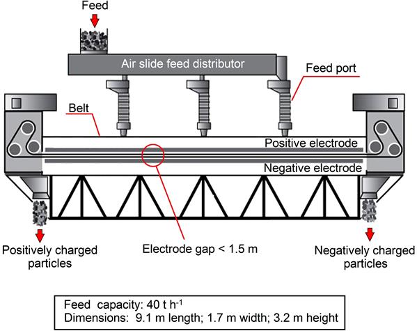
Recently a new triboelectric separator, the ST separator, has been developed by Separation Technologies which employs conventional interparticle contact to tribocharge mineral particles and a continuous loop open-mesh belt that travels at high speeds (5–20 m s−1) between positive and negative electrodes for particle separation (Figure 13.36) (Bittner et al., 2014). Feed enters from the top of the unit (at feed rates of up to 40 t h−1) with positive and negative charged particles exiting from opposite ends of the separator (Figure 13.37). The separation occurs within a narrow gap (<1.5 cm) between the electrodes. The top and bottom sections of the belt move in opposite directions, setting up a high particle number density, counter current flow within the electrode gap. Particles must travel across only a small fraction of the electrode gap (across the zone of high shear and lower velocities) under electrostatic forces to be separated into the oppositely flowing streams (Figure 13.38). The counter current highly turbulent flow enables multiple stages of separation to occur within a single pass through the separator, increasing both grade and recovery of the product streams (Bittner et al., 2014). This multistage separation zone requires that the particles maintain their charge, which is made possible due to the high degree of interparticle contacts occurring throughout the separation zone (Bittner et al., 2014). This separator can process particles from 1 to 300 μm, which is much smaller than conventional free-fall and HTR separators. It has been widely employed industrially in removing unburned coal char from fly ash (10–20 μm median diameter) generated by coal-fired power plants (Bittner et al., 2014). On a pilot plant scale (3–6 t h−1), it has also been shown to be effective at beneficiating industrial minerals such as separating quartz from calcite (89% recovery, 99% grade) and magnesite from talc (77% recovery, 95% grade) (Bittner et al., 2014).


13.6.4 Example Flowsheets
Earlier in this chapter the possibility of combined magnetic and electrical separation was noted, particularly in the processing of heavy mineral sand deposits. Table 13.3 shows some of the common minerals present in such alluvial deposits, along with their properties, related to magnetic and electrical separation. Mineral sands are commonly mined by floating dredges, feeding floating concentrators at up to 2,000 t h−1. Such concentrators, consisting of a complex circuit of sluices, spirals, or Reichert cones, upgrade the heavy mineral content to around 90%, the feed grades varying from less than 2%, up to 20% heavy mineral in some cases. The gravity preconcentrate is then transferred to the separation plant for recovery of heavy minerals by a combination of gravity, magnetic, and electrical (typically HTR) separation.
Table 13.3
Magnetic and Electrical Behavior of Typical Heavy Mineral Sands Components
| Magnetics | Magnetite—C | Ilmenite—C | Garnet—NC | Monazite—NC |
| Nonmagnetics | Rutile—C | Zircon—NC | Quartz—NC |

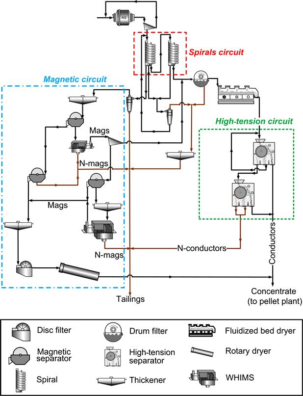
Mineral sands flowsheets vary according to the properties of the minerals present, wet magnetic separation often preceding high-tension separation where magnetic ilmenite is the dominant mineral, for example. A generalized flowsheet is shown in Figure 13.39. Low-intensity drum separators remove any magnetite from the feed, after which high-intensity wet magnetic separators separate the monazite and ilmenite from the zircon and rutile. Drying of these two fractions is followed by HTR separation to produce final products, although further cleaning is sometimes carried out by ESP separators. For example, screen electrostatic separators (Figure 13.34(b)) may be used to clean the zircon and monazite concentrates, removing fine conducting particles from these fractions. Similarly, plate electrostatic separators (Figure 13.34(a)) could be used to reject coarse nonconducting particles from the rutile and ilmenite concentrates.

Figure 13.40 shows a simplified circuit used to process heavy minerals, on the west coast of Australia (Benson et al., 2001).

The heavy mineral concentrate is first divided into conductive and nonconductive streams using HTR separators. The conductors are treated using cross-belt and roll magnetic separators to remove the ilmenite as a magnetic product. The nonmagnetic stream is cleaned with high-intensity roll and rare earth magnets to separate the weakly paramagnetic leucoxene from diamagnetic rutile. The nonconductors undergo another stage of wet gravity separation to remove quartz and other low-specific-gravity contaminants, before sizing and cleaning using HTR, ESP and Ultrastat separators to produce fine and coarse zircon products. Similar flowsheets are used in South-East Asia for the treatment of alluvial cassiterite deposits, which are also sources of minerals such as ilmenite, monazite, and zircon.
In the case of the Cliffs–Wabush mine (discussed in Section 13.5.3), the gravity concentrate from the spirals bank is cleaned by a series of HTR separators (Damjanović and Goode, 2000). The spiral concentrate is first filtered and dried before being fed to 54 primary Carpco HTR separators (with a total of 288 rotors), with the tailings from the rougher HTR separators fed to six scavenger HTR separators (total of 24 rotors). Each rotor is 10 ft long with a roll diameter of 14 in. and is operated at a rotor speed of 100 rpm, electrode voltage of 23–25 kV, and a feed rate of 2.54 t h−1. Through this separation, the nonconductive quartz gangue is pinned to the roll, with the valuable iron oxide mineral thrown from the roll. Cleaning of the gravity concentrate with HTR separators is preferred as relatively little material is pinned to the rotor in the high-tension treatment of the gravity concentrate (Fe-oxides are conductive). The rougher bank of HTR separators produces a final concentrate, a middlings stream that is recycled to the HTR feed and a tailings stream sent to the HTR scavenger circuit. The scavenger concentrate goes to the final concentrate (65.50% Fe, 2.55% SiO2, 1.95% Mn), with the scavenger tailings sent to the final tailings. The HTR concentrate is then blended with the magnetic concentrate prior to being sent to pelletization.