
Ore Handling
Ore handling is a key function in mining and mineral processing, which may account for 30–60% of the total delivered price of raw materials. It covers the processes of transportation, storage, feeding, and washing of the ore en route to, or during, the various stages of treatment in the mill.
Keywords
Ore transportation; conveyor; feeders; ore storage; self-heating
2.1 Introduction
Ore handling is a key function in mining and mineral processing, which may account for 30–60% of the total delivered price of raw materials. It covers the processes of transportation, storage, feeding, and washing of the ore en route to, or during, the various stages of treatment in the mill.
Since the physical state of ores in situ may range from friable, or even sandy material, to monolithic deposits with the hardness of granite, the methods of mining and provisions for the handling of freshly excavated material will vary widely. Ore that has been well fragmented can be transported by trucks, belts, or even by sluicing, but large lumps of hard ore may need secondary blasting. Developments in nonelectric millisecond delay detonators and plastic explosives have resulted in more controllable primary breakage and easier fragmentation of occasional overly-large lumps. At the same time, crushers have become larger and lumps up to 2 m in size can now be fed into some primary units.
Ores are by and large heterogeneous in nature. The largest lumps blasted from an open pit operation may be over 1.5 m in size. The fragmented ore from a blast is loaded directly into trucks, holding up to 400 t of ore in some cases, and is transported directly to the primary crushers. Storage of such ore is not always practicable, due to its wide particle size range which causes segregation during storage, the fines working their way down through the voids between the larger particles. Extremely coarse ore is sometimes difficult to start moving once it has been stopped. Sophisticated storage and feed mechanisms are therefore often dispensed with, the trucks depositing their loads directly on the grizzly feeding the primary crusher.
The operating cycle of an underground mine is complex. Drilling and blasting are often performed in one or two shifts; the blasted ore is hoisted to the surface during the next couple of shifts. The ore is transported through the passes via chutes and tramways and is loaded into skips, holding as much as 30 t of blasted ore, to be hoisted to the surface. Large boulders are often broken up underground by primary rock breakers in order to facilitate loading and handling at this stage. The ore, on arrival at the surface, having undergone some initial crushing, is easier to handle than that from an open pit mine. The storage and feeding is usually easier, and indeed essential, due to the intermittent arrival of skips at the surface.
2.2 The Removal of Harmful Materials
Ore entering the mill from the mine (run-of-mine ore) normally contains a small proportion of material which is potentially harmful to the mill equipment and processes. For instance, large pieces of iron and steel broken off from mine machinery can jam in the crushers. Wood is a major problem in many mills as it is ground into a fine pulp and causes choking or blocking of screens, flotation cell ports, etc. Wood pulp may also consume flotation reagents by absorption, which reduces mineral floatability. Clays and slimes adhering to the ore are also harmful as they hinder screening, filtration, and thickening, and again may consume flotation reagents.
All these tramp materials must be removed as far as possible at an early stage in treatment. Removal by hand (hand sorting) from conveyor belts has declined with the development of mechanized methods of dealing with large tonnages, but it is still used when plentiful cheap labor is available.
Skips, ore bins, and mill equipment can be protected from large pieces of “tramp” iron and steel, such as rockbolts and wire meshes, by electromagnets suspended over conveyor belts (guard magnets) (Figure 2.1). The magnets are generally installed downstream of the primary crusher to protect skips and ore bins. These powerful electromagnets can pick up large pieces of iron and steel travelling over the belt. They may operate continuously (as shown) or be stationary and, at intervals, are swung away from the belt and unloaded when the magnetic field is removed. Guard magnets, however, cannot be used to remove tramp iron from magnetic ores, such as those containing magnetite, nor will they remove nonferrous metals or nonmagnetic steels from the belt. Metal detectors, which measure the electrical conductivity of the material being conveyed, can be fitted over or around conveyor belts. The electrical conductivity of ores is much lower than that of metals, and fluctuations in electrical conductivity in the conveyed material can be detected by measuring the change that tramp metal causes in a given electromagnetic field. When a metal object triggers an alarm, the belt automatically stops and the object can be removed. With nonmagnetic ores it is advantageous to precede the metal detector with a guard magnet, which will remove the ferromagnetic tramp metals and thus minimize belt stoppages.

Large pieces of wood that have been flattened by passage through a primary crusher can be removed by passing the ore feed over a vibrating scalping screen. Here, the apertures of the screen are slightly larger than the maximum size of particle in the crusher discharge, allowing the ore to fall through the apertures and the flattened wood particles to ride over the screen and be collected separately. (On cold nights the collected wood might find a use.)
Wood can be further removed from the pulp discharge from the grinding mills by passing the pulp through a fine screen. Again, while the ore particles pass through the apertures, the wood collects on top of the screen and can be periodically removed.
Washing of run-of-mine ore can be carried out to facilitate sorting (Chapter 14) by removing obscuring dirt from the surfaces of the ore particles. However, washing to remove very fine material, or slimes, of little or no value is more important.
Washing is normally performed after primary crushing as the ore is then of a suitable size to be passed over washing screens. It should always precede secondary crushing as slimes severely interfere with this stage. The ore is passed through high-pressure jets of water on mechanically vibrated screens. The screen undersize product is usually directed to the grinding mills and thus the screen apertures are usually of similar size to the particles in the feed to the grinding mills.
Ore washing is sometimes assisted by adding scrubbers in the circuit. Scrubbers are designed to clean crushed ore, sand, and gravel, but they can also upgrade an ore by removing soft rock by attrition. Scrubbers are self-aligning, steel trunnions supported on flanged railroad type bearings, and driven by a saddle drive chain.
In the circuit shown in Figure 2.2, material passing over the screen, that is, washed ore, is transported to the secondary crushers. Material passing through the screens is classified into coarse and fine fractions by a mechanical classifier or hydrocyclone (Chapter 9), or both. It may be beneficial to classify initially in a mechanical classifier as this is more able to smooth out fluctuations in flow than is the hydrocyclone and it is better suited to handling coarse material.

The coarse product from the classifier, designated “washing plant sands,” is either routed direct to the grinding mills or is dewatered over vibrating screens before being sent to mill storage. A considerable load, therefore, is taken off the dry crushing section.
The fine product from classification, that is, the “slimes,” may be partially dewatered in shallow large diameter settling tanks known as thickeners (Chapter 15), and the thickened pulp is either pumped to tailings disposal or, if containing values, pumped direct to the concentration process, thus removing load from the grinding section. In Figure 2.2, the thickener overflows are used to feed the high-pressure washing sprays on the screens. Water conservation in this manner is practiced in most mills.
Wood pulp may again be a problem in the above circuit, as it will tend to float in the thickener, and will choke the water spray nozzles unless it is removed by retention on a fine screen.
2.3 Ore Transportation
In a mineral processing plant, operating at the rate of 400,000 t d−1, this is equivalent to about 28 t of solid per minute, requiring up to 75 m3 min−1 of water. It is therefore important to operate with the minimum upward or horizontal movement and with the maximum practicable pulp density in all of those stages subsequent to the addition of water to the system. The basic philosophy requires maximum use of gravity and continuous movement over the shortest possible distances between processing units.
Dry ore can be moved through chutes, provided they are of sufficient slope to allow easy sliding and sharp turns are avoided. Clean solids slide easily on a 15–25° steel-faced slope, but for most ores, a 45–55° working slope is used. The ore may be difficult to control if the slope is too steep.
The belt conveyor system is the most effective and widely used method of handling loose bulk materials in mining and mineral processing industries. In a belt conveyor system, the belt is a flexible and flat loop, mounted over two pulleys, one of which is connected to a drive to provide motion in one direction. The belt is tensioned sufficiently to ensure good grip with the drive pulley, and is supported by a structural frame, with idlers or slider bed in between the pulleys. Belts today have capacities up to 40,000 t h−1 (Alspaugh, 2008) and single flight lengths exceeding 15,000 m, with feasible speeds of up to 10 m s−1.
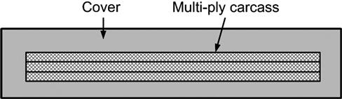
The standard rubber conveyor belt has a foundation, termed a carcass, of sufficient strength to withstand the belt tension, impact, and strains due to loading. This foundation can be single-ply or multi-ply (Figure 2.3) and is made of cotton, nylon, leather, plastic, steel fabric, or steel cord. The foundation is bound together with a rubber matrix and completely covered with a layer of vulcanized rubber. The type of vulcanized rubber cover may vary depending upon the ore properties and operational conditions (e.g., abrasiveness of ore, powder or lump material, temperature) (Ray, 2008).
The carrying capacity of the belt is increased by passing it over troughing idlers. These are support rollers set normal to the travel of the belt and inclined upward from the center so as to raise the edges and give it a trough-like profile. There may be three or five in a set and they will be rubber-coated under a loading point, so as to reduce the wear and damage from impact. Spacing along the belt is at the maximum interval that avoids excessive sag. The return belt is supported by horizontal straight idlers that overlap the belt by a few inches at each side. The idler dimensions and troughing angle are laid down in BIS in IS 8598:1987(2). The diameters of carrying and return idlers range from ca. 63 to 219 mm. Idler length may vary from 100 to 2,200 mm. Controlling factors for idler selection may include unit weight, lump size, and belt speed. The length of an idler is proportional to its diameter. The troughing idler sets are installed with a troughing angle ranging 15–50°. Idler spacing on the loaded side is a function of unit weight of material and belt width (Ray, 2008).
To control belt wandering (lateral movement), either training idlers are installed normal to the direction of the belt motion or wing idlers are installed at a forward angle. Sensors and electronic devices are also used to detect wandering and keep the belt on track (Anon., 2014).
The pulleys of belt conveyors are manufactured from rolled steel plates or from cast iron. The pulley drum is keyed to the steel shaft and the finished dimensions are machined. Generally, crowning is done to the pulley face to decrease belt wandering at the pulley. The length of the pulley is 100–200 mm more than the belt width (Ray, 2008). Inducing motion without slipping requires good contact between the belt and the drive pulley. This may not be possible with a single 180° turn over a pulley (wrap angle, α), and some form of “snubbed pulley” drive (Figure 2.4(a)) or “tandem” drive arrangement (Figure 2.4(b) and (c)) may be more effective. The friction can also be provided by embedded grooves or covering the pulleys with rubber, polyurethane, or ceramic layer of thickness 6–12 mm. The layer can also be engraved with patterned grooves for increased friction and better drainage when dealing with wet material (Ray, 2008).

The belt system must incorporate some form of tensioning device, also known as belt take-up load, to adjust the belt for stretch and shrinkage and thus prevent undue sag between idlers, and slip at the drive pulley. The take-up device also removes sag from the belt by developing tensile stress in the belt. In most mills, gravity-operated arrangements are used, which adjust the tension continuously (Figure 2.5). A screw type take-up loading system can be used instead of gravity for tensioning the conveyor (Ray, 2008). Hydraulics have also been used extensively, and when more refined belt-tension control is required, especially in starting and stopping long conveyors, load-cell-controlled electrical tensioning devices are used.

Advances in control technology have enhanced the reliability of belt systems by making possible a high degree of fail-safe automation. A series of belts should incorporate an interlock system such that failure of any particular belt will automatically stop preceding belts. Interlock with devices being fed by the belt is important for the same reasons. It should not be possible to shut down any machine in the system without arresting the feed to the machine at the same time and, similarly, motor failure should lead to the automatic tripping (stopping) of all preceding belts and machines. Similarly, the belt start up sequence of conveyor systems is fixed such that the last conveyor should start first followed by the second to last and so on. Sophisticated electrical, pneumatic, and hydraulic circuits have been widely employed to replace all but a few manual operations.
Several methods can be used to minimize loading shock on the belt. A typical arrangement is shown in Figure 2.6 where the fines are screened onto the belt first and provide a cushion for the larger pieces of rock. The impact loading on a belt can also be reduced by increasing the number of idlers at the loading points; such idlers are called impact idlers.

Feed chutes must be designed to deliver the bulk of the material to the center of the belt at a velocity close to that of the belt. Side boards or skirt plates with a length of 2–3 m are installed to guide the material on the belt and help reduce dust. Ideally the speed of material being placed should be equal to the belt speed, but in practice this condition is seldom achieved, particularly with wet sand or sticky materials. Where conditions will allow, the angle of the chute should be as great as possible, thereby providing sufficient velocity to the material in order to match the belt speed. The chute angle with the belt is adjusted until the correct speed of flow is obtained. Higher chute angles may produce impact loading on the belt. Material, particularly when heavy or lumpy, should never be allowed to strike the belt vertically. Baffles in transfer chutes, to guide material flow, are now often remotely controlled by hydraulic cylinders. Feed chutes are sometimes installed with hydraulically operated regulator gates for better control.
The conveyor may discharge at the head pulley, or the load may be removed before the head pulley is reached. The most satisfactory device for achieving this is a tripper. This is an arrangement of pulleys in a frame by which the belt is raised and doubled back so as to give it a localized discharge point. The frame is usually mounted on wheels, running on tracks, so that the load can be delivered at several points, over a long bin or into several bins. The discharge chute on the tripper can deliver to one or both sides of the belt. The tripper may be moved manually, by head and tail ropes from a reversible hoisting drum, or by a motor. It may be automatic, moving backward and forward under power from the belt drive. A plough can also be used to discharge the material. A plough is a v-shaped, rubber tipped blade extending along the width of the conveyor at an angle of 60°. A troughed conveyor is made flat by passing over a slider, at such a discharge point. Cameras allow the level of bin filling to be monitored.
Shuttle belts are reversible self-contained conveyor units mounted on carriages, which permit them to be moved lengthwise to discharge to either side of the feed point. The range of distribution is approximately twice the length of the conveyor. They are often preferred to trippers for permanent storage systems because they require less head room and, being without reverse bends, are much easier on the belt.
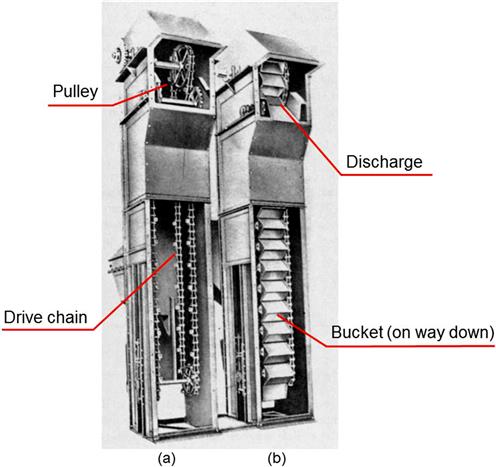
Belt conveyors can operate at a maximum angle of 10–18° depending on the material being conveyed. Beyond the range of recommended angle of incline, the material may slide down the belt, or it may topple on itself. Where space limitation does not permit the installation of a regular belt conveyor, steep angle conveying can be installed which includes gravity bucket elevators (Figure 2.7), molded cleat belts, fin type belts, pocket belts, totally enclosed belts, and sandwich belts. All these methods give only low handling rates with both horizontal conveying and elevating of the material. The gravity bucket elevators consist of a continuous line of buckets attached by pins to two endless roller chains running on tracks and driven by sprockets. The buckets are pivoted so that they always remain in an upright position and are dumped by means of a ramp placed to engage a shoe on the bucket, thus turning it into the dumping position.
Pipe conveyors were developed in Japan and are now being marketed throughout the world. This belt conveyor, after being loaded, is transformed into a pipe by arranging idlers. Five or six idlers are used to achieve the belt wrapping. The conveyor is unwrapped at the discharge point using idler arrangement and the belt is then passed over the head pulley in the conventional manner (Figure 2.8). The pipe conveyors are clean and environment friendly, especially when it comes to transporting hazardous material. This conveyor is compact and does not require a hood. It can efficiently negotiate horizontal curves with a short turning radius (McGuire, 2009).

Sandwich conveyor systems can be used to transport solids at steep inclines from 30° to 90°. The material being transported is “sandwiched” between two belts that hold the material in position and prevent it from sliding, rolling back or leaking back down the conveyor even after the conveyor has stopped or tripped. As pressure is applied to material to hold it in place, it is important that the material has a reasonable internal friction angle. Pressure is applied through roller arrangements, special lead-filled belts, belt weights, and tension in the belt (Figure 2.9). The advantage of sandwich belt conveyors is that they can transport material at steep angles at similar speeds to conventional belt conveyors (Walker, 2012). These belts can achieve high capacity and high lift. They can also accommodate large lumps. Belt cleaners can be used for cleaning the belts. The disadvantages include extra mechanical components and maintenance. These belts cannot elevate fine materials effectively (Anon., 2014).

Screw conveyors, also termed auger conveyors, are another means of transporting dry or damp particles. The material is pushed along a trough by the rotation of a helix, which is mounted on a central shaft. The action of the screw conveyor allows for virtually any degree of mixing of different materials and allows for the transportation of material on any incline from the horizontal to vertical. The screw conveyors are also capable of moving nonfree flowing and semi-solid materials (slurries) as well (Bolat and Boğoçlu, 2012; Patel et al., 2013). The main limitation of screw conveyors is the feed particle size and capacity, which has a maximum of ca. 300 m3 h−1 (Perry and Green, 1997).
Belt cleaners and washing systems are installed when handling sticky material (Figure 2.10). A fraction of the sticky material clings to the belt conveyor surface, which must be removed. Residual sticky material on the belt if not removed is carried back by the belt on the return side and may fall off at different points along the belt causing maintenance and housekeeping problems. The carry-back material also causes excessive wear, build up on return idlers, and misalignment and damage to the belt due to the accumulation of material. Belt cleaners and washing systems are generally installed near the discharge point (Anon., 2014).

Hydraulic transport of the ore stream normally takes over from dry transportation when ore is mixed with water, which is the grinding stage in most mills. Pulp may be made to flow through open launders by gravity in some cases. Launders, also termed flumes, are gently sloping troughs of rectangular, triangular, or semicircular section, in which the solid is carried in suspension, or by sliding or rolling. In mills, only fine sized ores (−5 mm) are transported. The slope must increase with particle size, with the solid content of the suspension, and with specific gravity of the solid. The effect of depth of water is complex: if the particles are carried in suspension, a deep launder is advantageous because the rate of solid transport is increased. If the particles are carried by rolling, a deep flow may be disadvantageous.
In plants of any size, the pulp is moved through piping via centrifugal pumps. Pipelines should be as straight as possible to prevent abrasion at bends. Abrasion can be reduced by using liners inside the pipelines. The use of oversize pipe is to be avoided whenever slow motion might allow the solids to settle and hence choke the pipe. The factors involved in pipeline design and installation are complex and include the solid–liquid ratio, the average pulp density, the density of the solid constituents, the size analysis and particle shape, and the fluid viscosity (Loretto and Laker, 1980).
Centrifugal pumps are cheap in capital cost and maintenance and occupy little space (Wilson, 1981; Pearse, 1985). Single-stage pumps are normally used, lifting up to 30 m and in extreme cases 100 m. The merits of centrifugal pumps include no drive seals, very little friction is produced in the pump, and almost no heat is transferred from the motor. Also, the centrifugal pump is not prone to breakage due to the coupling arrangement of the pump and motor (Wilson et al., 2006; Gülich, 2010). Their main disadvantage is the high velocity produced within the impeller chamber, which may result in serious wear of the impeller and chamber itself, especially when coarse sand is being pumped.
2.4 Ore Storage
The necessity for storage arises from the fact that different parts of the operation of mining and milling are performed at different rates, some being intermittent and others continuous, some being subject to frequent interruption for repair and others being essentially batch processes. Thus, unless reservoirs for material are provided between the different steps, the whole operation is rendered spasmodic and, consequently, uneconomical. Ore storage is a continuous operation that runs 24 h a day and 7 days a week. The type and location of the material storage depends primarily on the feeding system. The ore storage facility is also used for blending different ore grades from various sources.
The amount of storage necessary depends on the equipment of the plant as a whole, its method of operation, and the frequency and duration of regular and unexpected shutdowns of individual units.
For various reasons, at most mines, ore is hoisted for only a part of each day. On the other hand, grinding and concentration circuits are most efficient when running continuously. Mine operations are more subject to unexpected interruption than mill operations, and coarse-crushing machines are more subject to clogging and breakage than fine crushers, grinding mills, and concentration equipment. Consequently, both the mine and the coarse-ore plant should have a greater hourly capacity than the fine crushing and grinding plants, and storage reservoirs should be provided between them. Ordinary mine shutdowns, expected or unexpected, will not generally exceed a 24 h duration, and ordinary coarse-crushing plant repairs can be made within an equal period if a good supply of spare parts is kept on hand. Therefore, if a 24 h supply of ore that has passed the coarse-crushing plant is kept in reserve ahead of the mill proper, the mill can be kept running independent of shutdowns of less than a 24 h duration in the mine and coarse-crushing plant. It is wise to provide for a similar mill shutdown and, in order to do this, the reservoir between coarse-crushing plant and mill must contain at all times unfilled space capable of holding a day’s tonnage from the mine. This is not economically possible, however, with many of the modern very large mills; there is a trend now to design such mills with smaller storage reservoirs, often supplying less than a two-shift supply of ore, the philosophy being that storage does not do anything to the ore, and can, in some cases, has an adverse effect by allowing the ore to oxidize. Unstable sulfides must be treated with minimum delay, the worst case scenario being self-heating with its attendant production and environmental problems (Section 2.6). Wet ore cannot be exposed to extreme cold as it will freeze and become difficult to move.
Storage has the advantage of allowing blending of different ores so as to provide a consistent feed to the mill. Both tripper and shuttle conveyors can be used to blend the material into the storage reservoir. If the units shuttle back and forth along the pile, the materials are layered and mix when reclaimed. If the units form separate piles for each quality of ore, a blend can be achieved by combining the flow from selected feeders onto a reclaim conveyor.
Depending on the nature of the material treated, storage is accomplished in stockpiles, bins, or tanks. Stockpiles are often used to store coarse ore of low value outdoors. In designing stockpiles, it is merely necessary to know the angle of repose of the ore, the volume occupied by the broken ore, and the tonnage. The stockpile must be safe and stable with respect to thermal conductivity, geomechanics, drainage, dust, and any radiation emission. The shape of a stockpile can be conical or elongated. The conical shape provides the greatest capacity per unit area, thus reduces the plant footprint. Material blending from a stockpile can be achieved with any shape but the most effective blending can be achieved with elongated shape.
Although material can be reclaimed from stockpiles by front-end loaders or by bucket-wheel reclaimers, the most economical method is by the reclaim tunnel system, since it requires a minimum of manpower to operate (Dietiker, 1980). It is especially suited for blending by feeding from any combination of openings. Conical stockpiles can be reclaimed by a tunnel running through the center, with one or more feed openings discharging via gates, or feeders, onto the reclaim belt. Chain scraper reclaimers are the alternate device used, especially for the conical stock pile. The amount of reclaimable material, or the live storage, is about 20–25% of the total (Figure 2.11). Elongated stockpiles are reclaimed in a similar manner, the live storage being 30–35% of the total (Figure 2.12).


For continuous feeding of crushed ore to the grinding section, feed bins are used for transfer of the coarse material from belts and rail and road trucks. They are made of wood, concrete, or steel. They must be easy to fill and must allow a steady fall of the ore through to the discharge gates with no “hanging up” of material or opportunity for it to segregate into coarse and fine fractions. The discharge must be adequate and drawn from several alternative points if the bin is large. Flat-bottom bins cannot be emptied completely and retain a substantial tonnage of dead rock. This, however, provides a cushion to protect the bottom from wear, and such bins are easy to construct. This type of bin, however, should not be used with easily oxidized ore, which might age dangerously and mix with the fresh ore supply. Bins with sloping bottoms are better in such cases.
Pulp storage on a large scale is not as easy as dry ore storage. Conditioning tanks are used for storing suspensions of fine particles to provide time for chemical reactions to proceed. These tanks must be agitated continuously, not only to provide mixing but also to prevent settlement and choking up. Surge tanks are placed in the pulp flow-line when it is necessary to smooth out small operating variations of feed rate. Their content can be agitated by stirring, by blowing in air, or by circulation through a pump.
2.5 Feeding
Feeders are necessary whenever it is desired to deliver a uniform stream of dry or moist ore, since such ore will not flow evenly from a storage reservoir of any kind through a gate, except when regulated by some type of mechanism.
Feeding is essentially a conveying operation in which the distance travelled is short and in which close regulation of the rate of passage is required. Where succeeding operations are at the same rate, it is unnecessary to interpose feeders. Where, however, principal operations are interrupted by a storage step, it is necessary to provide a feeder. Feeders also reduce wear and tear, abrasion, and segregation. They also help in dust control and reduce material spillage. Feeder design must consider desired flow rates, delivery of a stable flow rate, the feeding direction, and particle size range of feed to be handled (Roberts, 2001).
A typical feeder consists of a small bin, which may be an integral part of a large bin, with a gate and a suitable conveyor. The feeder bin is fed by chutes, delivering ore under gravity. Feeders of many types have been designed, notably apron, belt, chain, roller, rotary, revolving disc, drum, drag scraper, screw, vane, reciprocating plate, table, and vibrating feeders. Sometimes feeders are not used and instead feeding is achieved by chutes only. Factors like type of material to be handled, the storage method, and feed rate govern the type of feeder (Anon., 2014).
In the primary crushing stage, the ore is normally crushed as soon as possible after its arrival. Many underground mines have primary crushers underground to reduce ore size and improve hoisting efficiency. Skips, trucks, and other handling vehicles are intermittent in arrival, whereas the crushing section, once started, calls for steady feed. Surge bins provide a convenient holding arrangement able to receive all the intermittent loads and to feed them steadily through gates at controllable rates. The chain-feeder (Figure 2.13) is sometimes used for smooth control of bin discharge.

The chain-feeder consists of a curtain of heavy loops of chain, lying on the ore at the outfall of the bin at approximately the angle of repose. The rate of feed is controlled automatically or manually by the chain sprocket drive such that when the loops of chain move, the ore on which they rest begins to slide.
Primary crushers depend for normal operation on the fact that broken rock contains a certain voidage (space between particles). If all the feed goes to a jaw crusher without a preliminary removal of fines, there can be danger of choking when there has been segregation of coarse and fine material in the bin. Such fines could pass through the upper zones of the crusher and drop into the finalizing zone and fill the voids. Should the bulk arriving at any level exceed that departing, it is as though an attempt is being made to compress solid rock. This choking, that is, packing of the crushing chamber (or “bogging”), is just as serious as tramp iron in the crusher and likewise can cause major damage. It is common practice, therefore, to “scalp” the feed to the crusher, heavy-duty screens known as grizzlies normally preceding the crushers and removing fines.
Primary crusher feeds, which scalp and feed in one operation, have been developed, such as the vibrating grizzly feeder (Chapter 8). The elliptical bar feeder (Figure 2.14) consists of elliptical bars of steel which form the bottom of a receiving hopper and are set with the long axes of the ellipses in alternate vertical and horizontal positions. Material is dumped directly onto the bars, which rotate in the same direction, all at the same time, so that the spacing remains constant. As one turns down, the succeeding one turns up, imparting a rocking, tumbling motion to the load. This works to loosen the fines, which sift through the load directly on to a conveyor belt, while the oversize is moved forward to deliver to the crusher. This type of feeder is probably better suited to handling high clay or wet materials such as laterite, rather than hard, abrasive ores.

The apron feeder (Figure 2.15) is one of the most widely used feeders for handling coarse ore, especially jaw crusher feed. The overlapping metal plates or pans mounted on strands of conveyor chains convey the material (Anon., 2014). It is ruggedly constructed, consisting of a series of high carbon or manganese steel pans, bolted to strands of heavy-duty chain, which run on steel sprockets. The rate of discharge is controlled by varying the speed or the height of the ribbon of ore by means of an adjustable gate. It can handle abrasive, heavy, and lumpy materials (Anon., 2014).

Apron feeders are often preferred to reciprocating plate feeders which push forward the ore lying at the bottom of the bin with strokes at a controllable rate and amplitude, as they require less driving power and provide a steadier, more uniform feed.
Belt feeders are essentially short belt conveyors, used to control the discharge of material from inclined chutes. The belt is flat and is supported by closely spaced idlers. They frequently replace apron feeders for fine ore and are increasingly being used to handle coarse, abrasive, friable primary crushed ore. Compared with apron feeders, they require less installation height, cost substantially less, and can be operated at higher speeds.
2.6 Self-Heating of Sulfide Minerals
Self-heating is a problem associated with many materials that affects how they are handled, stored, and transported (Quintiere et al., 2012). Self-heating is also referred to as spontaneous heating and pyrophoric behavior and results when the rate of heat generation (due to oxidation) exceeds the rate of heat dissipation. In the minerals industry, environmental effects of self-heating for coals are well documented, from the production of toxic fumes (CO, NOx, SO2) and greenhouse gases (CH4, CO2), to the contamination of runoff water (Kim, 2007; Stracher, 2007). There is also growing concern over self-heating of sulfides as regulations for shipping tighten (Anon., 2011).
Many base metals occur in nature as mineral sulfides, a form which has made their extraction, concentration, and conversion into metals a challenge, but a challenge that has been successfully met by technologies such as flotation, leaching, and autogenous smelting. The propensity of sulfur-containing materials to oxidize is largely the reason for the successful extraction of these metals, as well as the source of some of the associated problems of base metal processing. These problems include acid rock (acid mine) drainage (see Chapter 16), dust explosions, and self-heating of ores, concentrates, waste rock, tailings, and mine paste fill.
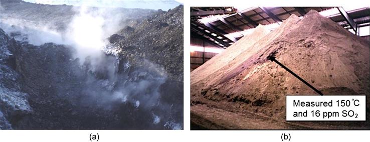
Heating may occur when the sulfide material is contained or piled in sufficient quantity (i.e., reducing the heat dissipation rate), with both oxygen (air) and some moisture present (ca. 3–8% by weight). If conditions are favorable, and this includes long storage times, presence of fine particles, high relative humidity, and temperatures exceeding 30°C, heating can proceed beyond 100°C, at which point SO2 gas begins to evolve and may continue to drive temperatures well in excess of 400°C (Rosenblum et al., 2001).
Figure 2.16 shows examples of waste rock (a) and concentrate (b) that have heated beyond 100°C leading to evolution of SO2. “Hot muck” underground at the Sullivan lead–zinc mine in British Columbia, Canada, made the cover of the CIM Bulletin magazine (June 1977). That mine first reported issues with self-heating of ore in 1926 (O’Brien and Banks, 1926), illustrating that the issues associated with sulfide self-heating have been around for considerable time. The sinking of the N.Y.K. Line’s SS Bokuyo Maru in 1939 was attributed to spontaneous combustion of copper concentrate (Kirshenbaum, 1968). The consequences are rarely so dramatic but can result in significant storage and transportation issues that may threaten infrastructure and the workplace environment.
Dealing with materials that have the potential to self-heat requires an understanding of the material reactivity and a proactive risk management approach (Rosenblum, et al., 2001). A variety of single-stage testing methods are in use for different materials with potential for self-heating (e.g., coal, wood chips, powdered milk). However, mineral sulfides require a two-stage assessment: one that mimics weathering (i.e., oxidation) at near ambient conditions and where elemental sulfur is created, followed by a higher temperature stage above 100°C to assess the impact of the weathering stage and where the elemental sulfur is oxidized to form SO2 (Rosenblum et al., 2014).
It is thought that the reactions governing self-heating are electrochemical as well as thermodynamic in origin (Payant et al., 2012; Somot and Finch, 2010). Pure sulfide minerals do not readily self-heat, the exception being pyrrhotite (Fe1−xS), likely due to its nonstochiometric excess of sulfur. Payant et al. (2012) have reported that a difference in the electrochemical rest potential between minerals in a binary mixture needs to exceed 0.2 V in order for self-heating to proceed. From Table 2.1, this means the pyrite–galena mix will self-heat, and that pyrite will accelerate self-heating of pyrrhotite, as observed experimentally (Payant et al., 2012). (See Chapter 12 for discussion of electrochemical effects.)
Table 2.1
Rest Potential Values of Some Sulfide Minerals
| Mineral | Formulaa | Rest Potential (vs. SHE) (V) |
| Pyrite | FeS2 | 0.66 |
| Chalcopyrite | CuFeS2 | 0.56 |
| Sphalerite | ZnS | 0.46 |
| Pentlandite | (Fe,Ni)9S8 | 0.35 |
| Pyrrhotite | Fe(1−x)S | 0.31 |
| Galena | PbS | 0.28 |
aNominal formula, natural samples can vary.
Source: From Payant et al. (2012).
Mitigation strategies used to control the risk of self-heating include controlling pyrrhotite content to below 10 %wt, monitoring for hot-spots with infrared thermal detectors, blending any hot material with cooler material, “blanketing” with CO2 (in ships’ holds, and storage sheds), drying to below 1 %wt moisture, and sealing with plastic (e.g., shipping concentrate in tote bags) to eliminate oxygen. The addition of various chemical agents to act as oxidation inhibitors is reportedly also practiced.