
Industrial Screening
Industrial screening is extensively used for size separations from 300 mm down to roughly 40 µm, although the efficiency decreases rapidly with fineness. Dry screening is generally limited to material above ca. 5 mm in size, while wet screening down to ca. 250 µm is common. Although there are screen types that are capable of efficient size separations down to 40 µm, sizing below 250 µm is more commonly undertaken by classification. Selection between screening and classification is influenced by the fact that finer separations demand large areas of screening surface and therefore can be expensive compared to classification for high-throughput applications.
Keywords
Screen performance; mathematical models; vibration modes; screen types; screening surfaces
8.1 Introduction
Industrial screening is extensively used for size separations from 300 mm down to roughly 40 µm, although the efficiency decreases rapidly with fineness. Dry screening is generally limited to material above ca. 5 mm in size, while wet screening down to ca. 250 µm is common. Although there are screen types that are capable of efficient size separations down to 40 µm, sizing below 250 µm is more commonly undertaken by classification (Chapter 9). Selection between screening and classification is influenced by the fact that finer separations demand large areas of screening surface and therefore can be expensive compared to classification for high-throughput applications.
The types of screening equipment are many and varied. Likewise, there are a wide range of screening objectives. The main purposes in the minerals industry are:
a. Sizing or classifying: to separate particles by size, usually to provide a downstream unit process with the particle size range suited to that unit operation.
b. Scalping: to remove the coarsest size fractions in the feed material, usually so that they can be crushed or removed from the process.
c. Grading: to prepare a number of products within specified size ranges. Examples include quarrying and iron ore processing, where the final product size is an important part of the specification.
d. Media recovery: for washing magnetic media from ore in dense medium circuits; or to retain grinding media inside grinding mills.
e. Dewatering: to drain free moisture from a wet sand slurry.
f. De-sliming or de-dusting: to remove fine material, generally below 0.5 mm, from a wet or dry feed.
g. Trash removal: usually to remove coarse wood fibers or tramp material from a slurry stream.
8.2 Screen Performance
In its simplest form, the screen is a surface having many apertures, or holes, usually with uniform dimensions. Particles presented to a screen surface either pass through or are retained, according to whether the particles are smaller or larger than the governing dimensions of the apertures. The efficiency of screening is determined by the degree of separation of the material into size fractions above and/or below the aperture size.
Efficiency Formulae
These can be derived from mass balances around a screen, Figure 8.1, where:
F(t h−1)=mass flow rate of feed material to the screen.
O(t h−1)=mass flow rate of the coarse product stream (oversize or overflow stream).
U(t h−1)=mass flow rate of the fine product stream (undersize or underflow stream).
f=mass fraction of feed material finer than a defined cut-point (or cut-size) (e.g., the screen aperture size).
o=mass fraction of material finer than the aperture size in the coarse product.
u=mass fraction of material finer than the aperture size in the fine product.

The mass fractions f, o, and u can be determined by sieve analysis on a representative sample of each stream on a laboratory screen of the same aperture size as the industrial screen.
At steady state, the overall solids mass balance on the screen is:
(8.1)
and the mass balance of the material finer than the screen aperture size is:
(8.2)
Several methods of defining screen performance exist (Colman and Tyler, 1980; Nichols, 1982; Bothwell and Mular, 2002; Valine and Wennen, 2002). Commonly, the fine product stream is the important one and efficiency is defined by the recovery of finished product (material less than cut-size) to the fine (underflow) stream, EU:
(8.3)
Equation (8.3) represents the actual mass of screen undersize that reports to the underflow, compared to the amount that should report theoretically, Ff. Solving for U/F by rearranging Eq. (8.1) and substituting into Eq. (8.2), the efficiency can be expressed in terms of the measured undersize mass fractions in each stream:
(8.4)
(8.5)
In most cases (and if there are no broken or deformed apertures), the amount of coarse material in the underflow is usually negligible and a simplification is to assume u=1 (i.e., all particles (100%) reporting to the fine product stream are below the screen aperture size), in which case the efficiency reduces to (f, o as fractions):
(8.6)
This is the efficiency equation used in Example 6.1 in Chapter 6 to calculate the flows around a closed crusher/screen circuit.
If, rather than the fine product, the coarse product is of more interest, a second definition of efficiency is recovery of oversize to the overflow, EO:
(8.7)
or, substituting for O/F in the same way as for U/F
(8.8)
Example 8.1 illustrates the use of the screen efficiency formulae.
Example 8.1
What is the %−12.7 mm in the screen underflow for 25.4 mm aperture screen if the feed to the screen is 50%−25.4 mm and 25%−12.7 mm given the screen efficiency is 85%?
Solution
To solve we need the efficiency of recovery of finished product to the underflow, Eq. (8.6). From this definition the mass flow rate of underflow U is
Assuming all-12.7 mm material in feed reports to underflow (reasonable):

Formulae such as these are acceptable for assessing the efficiency of a screen under different conditions, operating on the same feed. They do not, however, give an absolute value of the efficiency, as no allowance is made for the difficulty of the separation. A feed composed mainly of particles of a size near to that of the screen aperture—“near-size” (or “near-mesh”) material—presents a more difficult separation than a feed composed mainly of very coarse and very fine particles relative to the screen aperture.
Efficiency and Circulating Load
Circulation of material occurs in several parts of a mineral processing flowsheet, in grinding and flotation circuits, for example, as well as the crushing stage. In the present context, the circulating load (C) is the mass of coarse material returned from the screen to the crusher relative to the circuit final product (or fresh feed to the circuit), often quoted as a percentage. Figure 8.2 shows two closed circuit arrangements. Circuit (a) was considered in Chapter 6 (Example 6.1), and circuit (b) is an alternative. The symbols have the same meaning as before. The relationship of circulating load to screen efficiency for circuit (a) was derived in Example 6.1, namely (where all factors are as fractions):
(8.9)

In circuit (b), at steady state Eqs. (8.1–8.3) apply and the circulating load ratio C=O/U can be related to EU as follows:
From Eq. (8.1) dividing through by U:
and from the definition of EU we can substitute for F (=U/EU f, assuming u=1), giving:
(8.10)
The circulating load as a function of screen efficiency for the two circuits is shown in Figure 8.3. The circulating load increases with decreasing screen efficiency and as crusher product coarsens (f or r decreases), which is related to the crusher set (specifically the closed side setting, c.s.s.). For circuit (a) C also increases as the fresh feed coarsens (n decreases), which is likely coming from another crusher. In this manner, the circulating load can be related to crusher settings.

Efficiency or Partition Curve
For a screen this is drawn by plotting the partition coefficient, defined as the fraction (percentage) of the feed reporting to the oversize product, against the geometric mean size on a logarithmic scale. (For particles in the range, say, −8.0 +6.3 mm, the geometric mean size is √(8×6.3)=7.1 mm.) Figure 8.4 shows ideal and real partition curves (see also Chapter 9).

The separation size, or cut-point, is obtained at 50% recovery to oversize product, or 50% probability (i.e., the size of particle which has equal probability of reporting to the undersize or oversize product). The cut-point is always less than the size of the aperture.
The efficiency of separation is assessed from the steepness of the partition curve (see Chapter 9). The efficiency curve is used for simulation and design purposes (Napier-Munn et al., 1996; King, 2012).
Separation Efficiency
The efficiency definitions above refer to the recovery of finished product to either stream, for example, EU is recovery of finished product (material less than cut-size, or undersize) to the underflow stream. We could consider a separation efficiency as introduced in Chapter 1 (Eq. (1.2)), which is recovery of target material minus recovery of nontarget material. With respect to a screen, for the underflow we could consider the difference in recovery of undersize to the underflow minus recovery of oversize to the underflow, and an analogous statement could be made for the overflow, that is, recovery of oversize to the overflow minus recovery of undersize to the overflow. The appropriate equations can be derived, and this definition of screen efficiency may be of more use than the standard definitions in certain cases. The same could be applied to any particle size classifier, such as a cyclone.
8.3 Factors Affecting Screen Performance
Screen effectiveness must always be coupled with capacity as it is often possible, by the use of a low feed rate and a very long screening time, to effect an almost complete separation. At a given capacity, the effectiveness depends on the nature of the screening operation, that is, on the overall chance of a particle passing through the screen once it has reached it.
The process of screening is frequently described as a series of probabilistic events, where particles are presented to a screening surface many times, and on each presentation there exists a given probability that a particle of a given size will pass. In its simplest form, the probability of passage for a single spherical particle size d passing a square aperture with a size x bordered by a wire diameter w in a single event is given by Gaudin (1939):
(8.11)
or, given that the fraction of open area fo is defined as:
(8.12)
(8.13)
The probability of passage for n presentations is calculated by:
(8.14)
Screening performance is therefore affected by factors that influence the probability of particle passage, and factors that influence the number of opportunities the particles are given to pass through the screen mesh.
Particle Size
Taggart (1945) calculates some probabilities of passage related to the particle size using Eq. (8.14), which are shown in Table 8.1. The figures relate the probable chance per thousand of unrestricted passage through a square aperture of a spherical particle and give the probable number of apertures in series in the path of the particle necessary to ensure its passage through the screen.
Table 8.1
| Ratio of Particle to Aperture Size | Chance of Passage per 1,000 | Number of Apertures Required in Path |
| 0.001 | 998 | 1 |
| 0.01 | 980 | 2 |
| 0.1 | 810 | 2 |
| 0.2 | 640 | 2 |
| 0.3 | 490 | 2 |
| 0.4 | 360 | 3 |
| 0.5 | 250 | 4 |
| 0.6 | 140 | 7 |
| 0.7 | 82 | 12 |
| 0.8 | 40 | 25 |
| 0.9 | 9.8 | 100 |
| 0.95 | 2.0 | 500 |
| 0.99 | 0.1 | 104 |
| 0.999 | 0.001 | 106 |
It can be seen from Table 8.1 that as the particle size approaches that of the aperture, the chance of passage falls off very rapidly. The overall screening efficiency is markedly reduced by the proportion of these near-mesh particles. The effect of near-mesh particles is compounded because these particles tend to “plug” (also termed peg or blind) the apertures, reducing the available open area. This problem is often found on screens run in closed circuit with crushers, where a buildup of near-mesh material can occur and progressively reduces screening efficiency.
Feed Rate
The principle of sieve sizing analysis is to use a low feed mass and a long screening time to effect an almost complete (perfect) separation. In industrial screening practice, economics dictate that relatively high feed rates and short particle dwell times on the screen should be used. At high feed rates, a bed of material is presented to the screen, and fines must travel to the bottom of the particle bed before they have an opportunity to pass through the screen surface. The net effect is reduced efficiency. High capacity and high efficiency are often opposing requirements for any given separation, and a compromise is necessary.
Screen Angle
Equation (8.13) assumes that the particle approaches the aperture perpendicular to the aperture. If a particle approaches the aperture at a shallow angle, it will “see” a narrower effective aperture dimension and near-mesh particles are less likely to pass. The slope of the screening surface affects the angle at which particles are presented to the screen apertures. Some screens utilize this effect to achieve separations significantly finer than the screen aperture. For example, sieve bends (see Section 8.5.3) cut at approximately half the aperture size. Where screening efficiency is important, horizontal screens are selected.
The screen angle also affects the speed at which particles are conveyed along the screen, and therefore the dwell time on the screen and the number of opportunities particles have of passing the screen surface. Banana screens (see Section 8.5.1) incorporate a variable-angle slope which allows for increased throughput.
Particle Shape
Most granular materials processed on screens are nonspherical. While spherical particles pass with equal probability in any orientation, irregular-shaped near-mesh particles must orient in an attitude that permits them to pass. Elongated and slabby particles will present a small cross section for passage in some orientations and a large cross section in others. The extreme particle shapes therefore have a low screening efficiency: Mica, for instance, screens poorly on square aperture screens, its flat, plate-like crystals tending to “ride” over the screen apertures.
Open Area
The chance of passing through the aperture is proportional to the percentage of open area in the screen material (Eq. (8.13)), which is defined as the ratio of the net area of the apertures to the whole area of the screening surface (Eq. (8.12)). The smaller the area occupied by the screen deck construction material, the greater the chance of a particle reaching an aperture.
Open area generally decreases with the fineness of the screen aperture. In order to increase the open area of a fine screen, very thin and fragile wires or deck construction must be used. This fragility and the low-throughput capacity are the main reasons for classifiers replacing screens at fine aperture sizes. Advances in screen design continue to be made and examples of cyclones being replaced by screens are reported (Barkhuysen, 2009; Valine et al., 2009).
Vibration
Screens are vibrated in order to throw particles off the screening surface so that they can again be presented to the screen, and to convey the particles along the screen. The right type of vibration also induces stratification of the feed material (Figure 8.5), which allows the fines to work through the layer of particles to the screen surface while causing larger particles to rise to the top. Stratification tends to increase the rate of passage in the middle section of the screen (Soldinger, 1999).

The vibration must be sufficient to prevent pegging and blinding. However, excessive vibration intensity will cause particles to bounce from the screen deck and be thrown so far from the surface that there are very few effective presentations to the screen surface. Higher vibration rates can, in general, be used with higher feed rates, as the deeper bed of material has a “cushioning” effect that inhibits particle bounce.
Vibration can be characterized by the vibration frequency, v cycles per second, and amplitude, a meters. The term “stroke” is commonly used and refers to the peak-to-peak amplitude, or 2a. Generally, screening at larger apertures is performed using larger amplitudes and lower frequencies; whereas for fine apertures, small amplitudes and high frequencies are preferred. The intensity of vibration is defined by the vibration g-force, Γ:
(8.15)
Vibrating screens typically operate with a vibration force of between 3 and 7 times the gravitational acceleration, or 3–7 G. Vibrations are induced by mechanical exciters driven by electric motors, or electrical solenoids in the case of high-frequency screens. The power required is small compared to other unit operations within the concentrator and is approximately proportional to the loaded mass of the screen.
Moisture
The amount of surface moisture present in the feed has a marked effect on screening efficiency, as does the presence of clays and other sticky materials. Damp feeds screen poorly as they tend to agglomerate and “blind” the screen apertures. As a rule, dry screening at less than around 5 mm aperture size must be performed on perfectly material, unless special measures are taken to prevent blinding. These measures may include using heated decks to break the surface tension of water between the screen wire and particles, ball-decks (a wire cage containing balls directly below the screening surface) to impart additional vibration to the underside of the screen cloth, or the use of nonblinding screen cloth weaves.
Wet screening allows finer sizes to be processed efficiently down to 250 µm and less. Adherent fines are washed off large particles, and the screen is cleaned by the flow of pulp and additional water sprays.
8.4 Mathematical Models of Screens
Screen models aim to predict the size distribution and flow rate of the screen products. Models in the literature can be classified as:
1. phenomenological models that incorporate a theory of the screening process;
2. empirical models based on empirical data;
3. numerical models based on computer solutions of Newtonian mechanics.
Phenomenological Models
Phenomenological models are based on the theory of particle passage through a screening surface. The two dominant theories are probabilistic, treating the process as a series of probabilistic events, and kinetic, treating the process as one or more kinetic rate processes. These modeling approaches are comprehensively reviewed by Napier-Munn et al. (1996) and King (2012). They have been incorporated into simulators that help guide screen selection and operation.
Empirical Models
Empirical or capacity models aim to predict the required area of screen and are frequently used by screen manufacturers. There are a number of formulations of these models of the general form (Bothwell and Mular, 2002):
(8.16)
where F1 to Fn are correction factors and C is the base screen capacity in t h−1 per unit area when the other factors are 1.
One set of correction factors: account for the feed size distribution, namely: the quantity of oversize (material larger than the aperture), half-size (material less than half the aperture size), and near-size (material between 75% and 125% of the aperture size). Other factors include: the density of material being screened; whether the screen is a top deck or a lower deck on a multideck screen; the open area of the screen cloth; whether square or slotted apertures are used; whether wet-screening is employed; and the desired screening efficiency.
The values of the base capacity and for each of the factors are given in the form of tables or charts (e.g., Nichols, 1982). Karra (1979) converted the data into equation form to simplify use in spreadsheet calculations. A screen area calculation is given in Example 8.2.
Example 8.2
Size the screen in the crusher-screen closed circuit, Example 6.1.
Solution
A simplified screen area calculation is:
where F is feed rate to screen (t h−1), C the base capacity (t h−1 m−2), M is the “oversize” correction factor, and K is the “half-size” correction factor. The base capacity is empirically determined for a feed 25% coarser than the screen opening and 40% finer than half the screen opening (i.e., M=1 and K=1, respectively, under these feed conditions). As feeds vary from this size distribution corrections factors, M and K, and introduced. Some values of C, K, and M are given (Nichols, 1982); recall that the screen opening (aperture “a”) in Example 6.1 was 13 mm.
| Opening, a (mm) | Capacity, C (t h−1 m−2) | % + a | M | %−0.5 a | K |
| 13 | 41.5 | 40 | 1.10 | 25 | 0.7 |
| 19 | 51.5 | 45 | 1.13 | 30 | 0.8 |
| 25 | 59.0 | 50 | 1.18 | 35 | 0.9 |

For a=13 mm, from the capacity data
From Example 6.1, the feed rate, F, to the screen is:
M: require % + a (% +13 mm)
We can get to this by calculating f which is the %−13 mm
thus
and
To calculate need %−6.5 mm in fresh feed (N) and recycle stream (R).
In R, from crusher gradation table (c.s.s.=10 mm) %−6.5 mm~55%
thus
and
The calculated screen area A is then
Applying a safety factor:
Depending on availability, a 2.44 m by 5.5 m single deck screen meets the area requirement.
While these capacity-based calculations are popular, the information should be treated as a guide only (Olsen and Coombe, 2003). The calculations have been developed for specific screen-types: inclined circular stroke vibrating screens using standard wire-mesh screen. As there are many other variables, screen types, and screening surfaces in use, accurate screen selection for a particular application is best done by seeking advice from equipment suppliers in combination with pilot-scale testing. Compared to the crusher, the screen is considerably less costly, but failure to size the screen correctly will mean throughput will not be met. Flavel (1982) describes such a case.
Numerical Models
Numerical computer simulations are being increasingly used to model the behavior of particles in various processing equipment, including screens (Cleary, 2003). It is expected that numerical simulation techniques such as the Discrete Element Method will gain wider application in the modeling of industrial screens and assist in the design and optimization of new screening machines.
8.5 Screen Types
There are numerous types of industrial screens available. The dominant type is the vibrating screen, of which there are many subtypes in use for coarse and fine-screening applications.
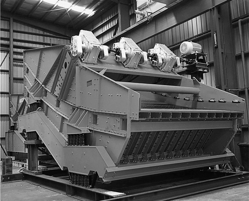
8.5.1 Vibrating Screens
Vibrating screens are the most important and versatile screening machines for mineral processing applications (Crissman, 1986). The success of the vibrating screen has made many older screen types obsolete in the minerals industry, including shaking and reciprocating screens, details of which can be found in Taggart (1945). Vibrating screens have a rectangular screening surface with feed and oversize discharge at opposite ends. They perform size separations from 300 mm down to 45 µm and they are used in a variety of sizing, grading, scalping, dewatering, wet screening, and washing applications.
Vibrating screens of most types can be manufactured with more than one screening deck. On multiple-deck systems, the feed is introduced to the top coarse screen, the undersize falling through to the lower screen decks, thus producing a range of sized fractions from a single screen.
Inclined or Circular Motion Screens
A vertical, circular or elliptical vibration is induced mechanically by the rotation of unbalanced weights or flywheels attached usually to a single drive shaft (see Section 8.5.2) (Figure 8.6). The amplitude of throw can be adjusted by adding or removing weight elements bolted to the flywheels. The rotation direction can be contra-flow or in-flow. Contra-flow slows the material more and permits more efficient separation, whereas in-flow permits a greater throughput. Single-shaft screens must be installed on a slope, usually between 15° and 28°, to permit flow of material along the screen.

Grizzly Screens
Very coarse material is usually screened on an inclined screen called a grizzly screen. Grizzlies are characterized by parallel steel bars or rails (Figure 8.7) set at a fixed distance apart and installed in line with the flow of ore. The gap between grizzly bars is usually greater than 50 mm and can be as large as 300 mm, with feed topsize as large as 1 m. Vibrating grizzlies are usually inclined at an angle of around 20° and have a circular-throw mechanism (Section 8.5.2). The capacity of the largest machines exceeds 5,000 t h−1.

The most common use of grizzlies in mineral processing is for sizing the feed to primary and secondary crushers. If a crusher has a 100 mm setting, then feed can be passed over a grizzly with a 100 mm gap in order to reduce the load on the crusher.
The bars are typically made from wear-resistant manganese steel and are usually tapered to create gaps that become wider toward the discharge end of the screen to prevent rocks from wedging between the bars. Domed or peaked profiles on the tops of the bars give added wear protection and prevent undersized rocks from “riding” along the bars and being misplaced.
Horizontal, Low-Head, or Linear Vibrating Screens
As shown in Figure 8.8, they have a horizontal or near-horizontal screening surface, and therefore need less headroom than inclined screens. Horizontal screens must be vibrated with a linear or an elliptical vibration produced by a double or triple-shaft vibrator (Section 8.5.2). The accuracy of particle sizing on horizontal screens is superior to that on inclined screens; however, because gravity does not assist the transport of material along the screen they have lower capacity than inclined screens (Krause, 2005). Horizontal screens are used in sizing applications where screening efficiency is critical, and in drain-and-rinse screens in heavy medium circuits (Chapter 11).

Resonance Screens
These is a type of horizontal screen consisting of a screen frame connected by rubber buffers to a dynamically balanced frame having a natural resonance frequency which is the same as that of the vibrating screen body. The vibration energy imparted to the screen frame is stored up in the balancing frame and reimparted to the screen frame on the return stroke. The energy losses are reduced to a minimum, and the sharp return motion produced by the resonant action imparts a lively action to the deck and promotes good screening.
Dewatering Screens
This type of vibrating screen receives a thick slurry feed and produces a drained sand product. Dewatering screens are often installed with a slight up-hill incline to ensure that water does not flow over with the product. A thick bed of particles forms, trapping particles finer than the screen aperture.
Banana or Multislope Screens
Becoming popular in high-tonnage sizing applications where both efficiency and capacity are important, banana screens (Figure 8.9) typically have a variable slope of around 40–30° at the feed end of the screen, reducing to around 0–15° in increments of 3.5–5° (Beerkircher, 1997). Banana screens are usually designed with a linear-stroke vibrator (Section 8.5.2).
The steep sections of the screen cause the feed material to flow rapidly at the feed end of the screen. The resulting thin bed of particles stratifies more quickly and therefore has a faster screening rate for the very fine material than would be possible on a slower moving thick bed. Toward the discharge end of the screen, the slope decreases to slow down the remaining material, enabling more efficient screening of the near-size material. The capacity of banana screens is reported to be up to three or four times that of conventional vibrating screens (Meinel, 1998).
Modular Screens
Units such as the OmniScreen (Figure 8.10) consist of two or more independent screen modules arranged in series, effectively making a large screen from a number of smaller units. A key advantage of this arrangement is that each screen module can be separately configured with a unique screen slope, screen surface type, vibration stroke, and frequency. This allows screening performance to be optimized separately on different sections of the screen. The individual screen sections. being smaller and lighter, are mechanically more robust compared with a single screen with an equivalent total area. Modular screens are frequently installed in a multislope configuration.

Mogensen Sizer
This is a vibrating screen exploiting the principle that particles smaller than the aperture statistically require a certain number of presentations to the screen in order to pass (refer to Table 8.1). The Mogensen Sizer (Figure 8.11) consists of a system of oscillating and sloping screens of decreasing aperture size, the smallest of which has a mesh size up to twice the size of the desired separation size (Hansen, 2000). This arrangement allows particles very much finer than the screen apertures to pass through quickly while causing larger particles to be rejected by one of the screen surfaces.

A thin layer of particles on each screen surface is maintained, enabling high capacity such that a particular screening duty can be met with a machine occupying less floor space than a conventional screen, and blinding and wear are reduced. The units typically range in size from 0.5 to 3.0 m wide and can contain up to six decks.
High-Frequency Screens
Efficient screening of fine particles requires a vibration with small amplitude and high frequency. Frequencies up to 3,600 rpm are used to separate down to 100 µm, compared with vibrating screens for coarser applications that are vibrated at around 700–1,200 rpm. The vibration of the screening surface can be created by electric motors or with electrical solenoids. In the case of the Tyler H-series (or Hum-mer) screens, the vibrators are mounted above and connected by rods directly to the screening surface so that energy is not wasted in vibrating the entire screen body.
Derrick Stack Sizer®
Widely used in wet screening applications, the Stack Sizer® comprises up to five individual screen decks positioned one above the other operating in parallel (Figure 8.12). The “stacked” design allows for high-capacity units in a small footprint. The flow distributor (Flo-Divider™) splits the feed stream evenly to the individual polyurethane screen decks (openings down to 45 µm) where feeders distribute the stream across the entire width (up to 6 m) of each screen. Dual vibratory motors provide uniform linear motion to all screen decks. The undersize and oversize streams are individually combined and exit toward the bottom of the Stack Sizer®. Repulp sprays and trays are an optional addition in between screen sections, which allow for increased screen efficiency.

By classifying by size-only, screens compared to hydrocyclones, give a sharper separation with multidensity feeds (for example, in Pb–Zn operations), and reduce overgrinding of the dense minerals. Valine et al. (2009) document several concentrators in base metals, phosphate, and iron ore operations that replaced hydrocyclones with Stack Sizers® in closing ball mill circuits. An example is the Minera Cerro Lingo (Peru) operation, which produces copper, lead, and zinc concentrates, where 26-in. (66 cm) diameter hydrocyclones in the ball mill circuit were replaced with four Stack Sizers. The result was a decrease in the circulating load from 260% to 108% and 14% increase in circuit throughput.
8.5.2 Vibration Modes
Circular Motion (Single-Shaft) Screens
When the shaft of an inclined screen is located precisely at the screen’s center of gravity, the entire screen body vibrates with a circular vibration pattern (Figure 8.13(a)). Occasionally, the shaft is installed above or below the center of gravity, as in the system shown in Figure 8.13(b). This placement results in an elliptical motion, slanting forward at the feed end, a circular motion at the center, and an elliptical motion, slanting backward at the discharge end. Forward motion at the feed end serves to move oversize material rapidly out of the feed zone to keep the bed as thin as possible. This action facilitates passage of fines which should be completely removed in the first one-third of the screen length. As the oversize bed thins, near the center of the screen the motion gradually changes to the circular pattern to slow down the rate of travel of the solids. At the discharge end, the oversize and remaining near-size materials are subjected to the increasingly retarding effect of the backward elliptical motion. This allows the near-size material more time to find openings in the screen cloth.

Linear-Vibration (Double-Shaft) Screens
A linear vibration is induced by using mechanical exciters containing matched unbalanced weights rotating in opposite directions on two shafts, as shown in Figure 8.13(c). Linear stroke screens can be installed on a slope, horizontally or even on a small up-hill incline. The angle of stroke is typically between 30° and 60° to the screen deck. Linear-vibration exciters are used on horizontal screens and banana screens.
Oval Motion (Triple-Shaft) Screens
A three-shaft exciter design can be used to generate an elliptical vibratory motion, as shown in Figure 8.13(d), which can also be used on horizontal and banana screens. The three shafts are connected by gears and one of the shafts is driven. The elliptical motion is claimed to offer the efficiency benefit of a linear vibrating screen with the tumbling action of a circular motion screen. Higher capacities and increased efficiencies are claimed over either linear or circular motion machines.
8.5.3 Other Screen Types
Static Grizzlies
With no vibration mechanism, these units are used in scalping applications. They are installed at a slope of 35–50° to assist material flow (Taggart, 1945). Static grizzlies are less efficient than their vibrating counterparts and are usually used when the proportion of oversize material in the feed is small.
Mogensen Divergators
Along with self-cleaning grizzly screens (Figure 8.14), they use round bars in two rows—alternate bars at different angles, and fixed at one end to prevent the possibility of blinding. Divergators are used for coarse separations between 25 and 400 mm. Divergators are used in grizzly scalping duties and in chutes to direct the fine material onto the conveyor first to cushion the impact from coarser lumps.

Trommels
These revolving screens are one of the oldest screening devices (Figure 8.15), comprising a cylindrical screen typically rotating at between 35% and 45% critical speed. Trommels are installed on a small angle to the horizontal or use a series of internal baffles to transport material along the cylinder. Trommels can be made to deliver several sized products by using trommel screens in series from finest to coarsest such as the one shown; or using concentric trommels with the coarsest mesh being innermost. Trommels can handle material from 55 mm down to 6 mm, and even smaller sizes can be handled under wet screening conditions. Although trommels are typically cheaper, vibration-free, and mechanically robust, they generally have lower capacities than vibrating screens since only part of the screen surface is in use at any one time, and they can be more prone to blinding.

Trommels remain widely used in some screening duties, including aggregate screening plants and the screening of mill discharge streams. Tumbling mill (AG, SAG, rod, and ball mills) discharge streams usually pass through a trommel screen attached to the mill outlet to prevent grinding media scats from reaching subsequent processing equipment, and the case of AG/SAG mills, to extract pebbles to send to crushing (Chapters 6 and 7). Trommels are also used for wet-scrubbing ores, such as bauxite.
Rotaspiral
Introduced in 2001 by Particle Separation Systems, it is a trommel-like device designed for fine screening between 1,000 and 75 µm. The drum contains an internal spiral to move the material through the screen. Water sprays are used to fluidize the screen bed and wash the screen surface. The Rotaspiral can also be used in a dewatering duty.
Bradford Breaker
A variation of the trommel screen, it is employed in the coal industry (see also Chapter 6). It serves a dual function of breaking coal, usually to between 75 and 100 mm, and separating the harder shale, rock, tramp metal, and wood contaminants into the oversize. Bradford breakers are operated at between 60% and 70% critical speed (see Chapter 7).
Roller Screens
Used for screening applications from 3 to 300 mm (Clifford, 1999), roller screens (Figure 8.16) use a series of parallel driven rolls (circular, elliptical, or profiled) or discs to transport oversize while allowing fines to fall through the gaps between the rolls or discs. They offer advantages of high capacity, low noise levels, require little head-room, subject the material to little impact, and permit screening of very sticky materials.

Flip-Flow Screen
The concept used in the Liwell “Flip-flow” screens is a system of flexible screen panels that are alternately stretched and relaxed to impart motion to the screen bed instead of relying only on mechanical vibration of the screen body. The throwing action can generate forces of up to 50 G on the screen surface, preventing material from blinding the apertures. The screen body may be static or subjected to accelerations in the range 2–4 G (Kingsford, 1991).
Flip-flow screens can be used for separations ranging from 0.5 up to 50 mm and for feed rates up to 800 t h−1. Flip-flow screens are particularly suited for fine separations of damp material that cannot be screened efficiently on conventional vibrating screens (Meinel, 1998). Both roller and flip-flow screens are now finding application in coal preparation plants where damp feeds blind standard vibrating screens (Luttrell, 2014).
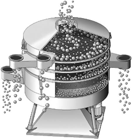
Circular, Gyratory, or Tumbler Screens
As shown in Figure 8.17, they impart a combined gyratory and vertical motion and are used for fine-screening applications, wet or dry, down to 40 µm, including laboratory use. The basic components consist of a nest of sieves up to around 2.7 m in diameter supported on a table that is mounted on springs on a base. Suspended from beneath the table is a motor with double-shaft extensions, which drives eccentric weights and in doing so effects horizontal gyratory motion. Vertical motion is imparted by the bottom weights, which swing the mobile mass about its center of gravity, producing a circular tipping motion to the screen, the top weights producing the horizontal gyratory motion. Ball trays and ultrasonic devices may be fitted below the screen surfaces to reduce blinding. Circular screens are often configured to produce multiple size fractions. These types of screens are typically used in low-capacity applications, one example being the dewatering of carbon in gold plants.
Sieve Bends
Along with inclined flat screens, sieve bends are used for dewatering and fine screening applications. The sieve bend has a curved screen composed of horizontal wedge bars, whereas flat screens are installed on a slope of between 45° and 60°. Feed slurry enters the upper surface of the screen tangentially and flows down the surface in a direction perpendicular to the openings between the wedge bars. As the stream of slurry passes each opening a thin layer is peeled off and directed to the underside of the screen. In general, a separation is produced at a size roughly half the bar spacing and so little plugging of the apertures should take place. Separation can be undertaken down to 50 µm and screen capacities are up to 180 m3 h−1.
One of the most important applications for sieve bends is in draining water from the feed to drain and rinse screens in dense medium separation circuits. When treating abrasive materials sieve bends will require regular reversal of the screen surface as the leading edge of the apertures will lose their sharpness over time.
Sieve bends and inclined wedge-wire screens are sometimes installed with mechanical devices to periodically vibrate or rap the screen surface in order to remove blinded particles.
Linear Screen
Developed by Delkor (now Tenova Delkor), this screen is predominantly used for removing wood chips and fiber from the ore stream feeding carbon-in-pulp systems, and for the recovery of loaded carbon in gold CIP circuits (Walker, 2014). The machine (Figure 8.18) comprises a synthetic monofilament screen cloth supported on rollers and driven by a head pulley coupled to a variable speed drive unit. Mesh sizes in use are typically around 500 µm. Dilute slurry enters through a distributor on to the moving cloth. The undersize drains through the cloth by gravity and is collected in the underpan. The oversize material retained on the screen is discharged at the drive pulley, and any adhering material is washed from the screen cloth using water sprays. As the screen is not vibrated, linear screens are quiet and the energy consumption is much less than that required for vibrating screens.

Pansep Screen
It has a similar principle to the linear screen, but rather than a continuous screen surface, the deck is divided into a series of pans that move in a manner similar to a conveyor (Figure 8.19). The base of each pan consists of a tensioned wire screen mesh, permitting finer cut-points than on linear screens. Cut-points in the range 45–600 µm are possible. Screening occurs both on the top of the “conveyor” motion and on the bottom, giving high screening capacity for the occupied foot print. As well, a deck cleaning action is provided by continually reversing the screening direction (Buisman and Reyneke 2000; Mohanty, 2003). Panels are washed twice each rotation.

8.5.4 Screening Surfaces
There are many types of screening surface available. The size and shape of the apertures, the proportion of open area, the material properties of the screening surface, and flexibility of the screen surface can be critical to the performance of a screening machine.
Screening surfaces are usually manufactured from steel, rubber, or polyurethane and can be classified according to how they are fixed to the screen. Bolt-in, tensioned, and modular fixing systems are used on industrial vibrating screens.
Bolt-In Screening Surfaces
Screening surfaces for screening duties with particles larger than around 50 mm frequently consist of large sheets of punched, laser-cut, or plasma-cut steel plate, often sandwiched with a polyurethane or rubber wear surface to maximize wear life. These sheets are rigid and are bolted to the screen (Figure 8.20). Curved sections of screens of this type are also commonly used on trommels.

These screening surfaces are available with custom-designed aperture shapes and sizes. Apertures usually have a tapered profile, becoming wider with depth, thereby reducing the propensity of particles pegging in the aperture.
Tensioned Screening Surfaces
These screen surfaces consist of cloths that are stretched taut, either between the sides of the screen (cross tensioned) or along the length of the screen (end tensioned). Maintaining the correct tension in the screen cloth is essential to ensure screening efficiency and to prevent premature failure of the screening surface. Tensioned screens are available in various wire weaves as well as polyurethane and rubber mats.
Woven-Wire Cloth
Usually constructed from steel or stainless steel, these traditional screen surfaces remain popular. Wire cloths are the cheapest screening surfaces, have a high open area, and are comparatively light. The high open area generally allows a screen to be smaller than a screen with modular panels for the same capacity duty. In relatively light screening duties, therefore, wire-tensioned screens are often preferred. Increasing the wire thickness increases their strength, but decreases open area and hence capacity.
Various types of square and rectangular weaves are available. Rectangular screen apertures have a greater open area than square-mesh screens of the same wire diameter. The wire diameter chosen depends on the nature of the work and the capacity required. Fine screens can have the same or greater open areas than coarse screens, but the wires used must be thinner and hence are more fragile.
“Self-Cleaning” Wire
Traditionally, blinding problems have been countered by using wire with long-slotted apertures or no cross-wires at all (“piano-wire”), but at the cost of lower screening efficiency. Self-cleaning wire (Figure 8.21) is a variation on this, having wires that are crimped to form “apertures”, but individual wires are free to vibrate and therefore have a high resistance to blinding and pegging. Screening accuracy can be close to that of conventional woven wire mesh; and they have a longer wear life, justifying their higher initial cost. There are three main types of self-cleaning weave: diamond, triangle, and wave or zig-zag shaped apertures. The triangle and diamond weaves give a more efficient separation.

Tensioned Rubber and Polyurethane Mats
Interchangeable with tensioned wire cloths, these mats are usually reinforced with internal steel cables or synthetic cords. Polyurethane and rubber screen decks (Figure 8.22) are popular in harsh screening duties. They are usually assembled in modules or panels that are fixed onto a subframe (modular screening). Both materials offer exceptional resistance to abrasion and can have significantly longer wear life than steel, although the open area is generally lower than wire. Rubber also has excellent impact resistance; therefore rubber is often used in applications where top size can be greater than around 50 mm. Polyurethane is generally preferred in wet screening applications. Aggregate producers prefer tensioned mats because they must be able to make frequent deck changes to produce different specifications, and tensioned mats are quicker to replace than modular screening systems.

Modular polyurethane and rubber screen panels are typically 305 mm×305 mm, 610 mm×305 mm, or similar, in size. The edges of the panel usually contain a rigid steel internal frame to give the panel strength. Panel systems allow for rapid replacement of the deck. Different panel types and aperture sizes can be installed at different positions along the screen to address high wear areas and to optimize any given screening task. Modular screens do not require tensioning and retensioning and damaged sections of the screen can be replaced in situ. Polyurethane and rubber screens are also quieter, and the more flexible apertures reduce blinding compared with steel wire cloths.
Square, rectangular, and slot apertures are the most commonly used aperture shapes. Rectangular and slot apertures can be in-flow (usual for sizing applications), cross-flow (usual for dewatering applications), or diagonal. With slabby particles rectangular and slot apertures provide greater open area, throughput, resistance to pegging, and efficiency compared with square apertures. Other aperture shapes include circles, hexagons, octagons, rhomboids, and tear-drops. Combinations of shapes and configurations are also possible. Circular apertures are considered to give the most accurate cut, but are more prone to pegging. Slotted, tear-drop, and more complex aperture shapes are used where blinding or pegging can be a problem. Apertures are tapered, being wider at the bottom than the top, to ensure that a particle that has passed through the aperture at the deck surface can fall freely to undersize.
Modular Wire and Wedge Wire Panels
These have much greater open area compared with modular polyurethane screens. These wire panels consist of a polyurethane or rubber fixing system molded around a woven-wire or wedge-wire screening surface.