
Grinding Mills
Grinding is the last stage in the comminution process where particles are reduced in size by a combination of impact and abrasion, either dry, or more commonly, in suspension in water. It is performed in cylindrical steel vessels that contain a charge of loose crushing bodies—the grinding medium—which is free to move inside the mill, thus comminuting the ore particles. According to the ways by which motion is imparted to the charge, grinding mills are generally classified into two types: tumbling mills and stirred mills. In tumbling mills, the mill shell is rotated and motion is imparted to the charge via the mill shell. The grinding medium may be steel rods, balls, or rock itself. Media ball sizes, for example, range from about 20 mm for fine grinding to 150 mm for coarse grinding. Tumbling mills are typically employed in the mineral industry for primary grinding (i.e., stage immediately after crushing), in which particles between 5 and 250 mm are reduced in size to between 25 and 300 µm. In stirred mills, the mill shell is stationary mounted either horizontally or vertically and motion is imparted to the charge by the movement of an internal stirrer. Ginding media (25 mm or less) inside the mill are agitated or rotated by the stirrer, which typically comprises a central shaft to which are attached screws, pins or discs of various designs. Stirred mills find application in regrinding, fine (15–40 µm) and ultra fine (<15 µm) grinding.
Keywords
Tumbling mill; stirred mills; power draw; mill construction; mill sizing; circuits and control
7.1 Introduction
Grinding is the last stage in the comminution process where particles are reduced in size by a combination of impact and abrasion, either dry, or more commonly, in suspension in water. It is performed in cylindrical steel vessels that contain a charge of loose crushing bodies—the grinding medium—which is free to move inside the mill, thus comminuting the ore particles. According to the ways by which motion is imparted to the charge, grinding mills are generally classified into two types: tumbling mills and stirred mills. In tumbling mills, the mill shell is rotated and motion is imparted to the charge via the mill shell. The grinding medium may be steel rods, balls, or rock itself. Media ball sizes, for example, range from about 20 mm for fine grinding to 150 mm for coarse grinding. Tumbling mills are typically employed in the mineral industry for primary grinding (i.e., stage immediately after crushing), in which particles between 5 and 250 mm are reduced in size to between 25 and 300 µm. In stirred mills, the mill shell is stationary mounted either horizontally or vertically and motion is imparted to the charge by the movement of an internal stirrer. Grinding media (25 mm or less) inside the mill are agitated or rotated by the stirrer, which typically comprises a central shaft to which are attached screws, pins, or discs of various designs. Stirred mills find application in regrinding, fine (15–40 µm) and ultrafine (<15 µm) grinding.
All ores have an economic optimum particle size which maximizes the difference between net smelter return (NSR) and grinding costs (Chapter 1): too coarse a grind and the inadequate liberation limits recovery (and thus revenue) in the separation stage; too fine a grind and grinding costs exceed any increment in recovery (and may even reduce recovery depending on the separation process). The optimum grind size will depend on many factors, including the extent to which the values are dispersed in the gangue, and the subsequent separation process to be used. It is the purpose of the grinding section to exercise close control on this product size and, for this reason, correct grinding is often said to be the key to good mineral processing.
Grinding costs are driven by energy and steel (media, liners, etc.) consumption; grinding is the most energy-intensive operation in mineral processing. On a survey of the energy consumed in a number of Canadian copper concentrators it was shown that the average energy consumption in kWh t−1 was 2.2 for crushing, 11.6 for grinding, and 2.6 for flotation (Joe, 1979). It can be shown, using Bond’s equation (Equation 5.4), that 19% extra energy must be consumed in grinding one screen size finer on a ![]() screen series. A strategy to reduce grinding energy consumption in low grade high tonnage flotation plants is to employ a coarse primary grind and regrind the rougher flotation concentrate, which represents a much lower tonnage. This has driven development of coarse flotation technology (see Chapter 12), and energy efficient regrinding (see later in this chapter).
screen series. A strategy to reduce grinding energy consumption in low grade high tonnage flotation plants is to employ a coarse primary grind and regrind the rougher flotation concentrate, which represents a much lower tonnage. This has driven development of coarse flotation technology (see Chapter 12), and energy efficient regrinding (see later in this chapter).
Although tumbling mills have been developed to a high degree of mechanical efficiency and reliability, their energy efficiency (conversion of energy delivered by the mill into broken material) remains an area of debate. Breakage of the ore is mostly the result of repeated, random impact and abrasion, events which break liberated as well as unliberated particles. At present there is no practical way that these impacts can be directed at the interfaces between the mineral grains, which would produce optimum liberation (liberation by detachment), although various ideas have been postulated (Wills and Atkinson, 1993). Assisted breakage through application of such technologies as microwave heating (Jones et al., 2006) and high voltage pulsing (van der Wielen et al. 2014) aims to increase liberation and reduce overall grinding energy consumption by creating multiple internal stresses and micro-cracks, that is weakening the ore prior to tumble milling.
Although the economic degree of liberation is the principal purpose of grinding in mineral processing, grinding is sometimes used to increase mineral surface area. Production of some industrial minerals such as talc involves size reduction to meet customer requirements, and iron ore concentrates are reground to produce pelletizer feed. Where grinding is followed by hydrometallurgical methods of extraction, as in gold-ore processing, a high surface area increases cyanide leaching rate and in such cases extensive grinding may not be a disadvantage, as the increase in energy consumption may be offset by the increased gold recovery.
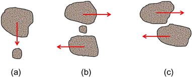
Grinding within a tumbling mill is influenced by the size, quantity, the type of motion, and the spaces between the individual pieces of the medium in the mill. As opposed to crushing, which takes place between relatively rigid surfaces, grinding is a random process. The degree of grinding of an ore particle depends on the probability of the ore entering a zone between the medium entities (balls, etc.) and the probability of some breakage event occurrence after entry. Grinding can be achieved by several mechanisms, including: impact or compression due to sudden forces applied almost normally to the particle surface; chipping or attrition due to steady forces that break the matrix of a particle; and abrasion due to forces acting parallel to and along the surfaces (i.e., shear) (Figure 7.1). These mechanisms distort the particles and change their shape beyond certain limits determined by their degree of elasticity, which causes them to break.
Grinding is usually performed wet, although dry grinding is used in applications such as cement production or when a material is simultaneously ground and dried. Water conservation efforts may see an increase in dry grinding in the future. In the mill, the mixture of medium, ore, and water, known as the mill charge, is intimately mixed, the medium comminuting the particles by any of the above methods.
Apart from laboratory testing, grinding in mineral processing is a continuous process, material being fed at a controlled rate into one end of the mill and discharging at the other end after a suitable dwell (residence) time. Control of product size is exercised by the properties of the mill charge, the nature of the ore feed, and the type of mill and circuit used.
7.2 Tumbling Mills
Tumbling mills are of three basic types: rod, ball, and autogenous/semi-autogenous (AG/SAG), based on the type of grinding media (SAG mills are AG mills with some grinding balls). Structurally, each type of mill consists of a horizontal cylindrical shell, provided with renewable wearing liners and a charge of grinding medium. The drum is supported so as to rotate on its axis on hollow trunnions attached to the end walls (Figure 7.2). The diameter of the mill determines the impact that can be exerted by the medium on the ore particles and, in general, the larger the feed size the larger the mill diameter needs to be. The length of the mill, in conjunction with the diameter, determines the volume, and hence the capacity of the mill.

Material is usually fed to the mill continuously through one end trunnion, the ground product leaving via the other trunnion, although in certain applications the product may leave the mill through a number of ports spaced around the periphery of the shell. All types of mill can be used for wet or dry grinding by modification of feed and discharge equipment.
7.2.1 Motion of the Charge
The distinctive feature of tumbling mills is the use of loose crushing bodies, which are large, hard, and heavy in relation to the ore particles, but small in relation to the volume of the mill, and which occupy (including voids) slightly less than half the volume of the mill.
Due to the rotation and friction of the mill shell, the grinding medium is lifted along the rising side of the mill until a position of dynamic equilibrium is reached (the shoulder), when the bodies cascade and cataract down the free surface of the other bodies, about a dead zone where little movement occurs, down to the toe of the mill charge (Figure 7.3).

The driving force of the mill is transmitted via the liner to the charge. The speed at which a mill is run and the liner design governs the motion and thus nature of the product and the amount of wear on the shell liners. For instance, a practical knowledge of the trajectories followed by the steel balls in a mill determines the speed at which it must be run in order that the descending balls shall fall on to the toe of the charge, and not on to the liner, which could lead to liner damage. Simulation of charge motion can be used to identify such potential problems (Powell et al., 2011), and acoustic monitoring can give indication of where ball impact is occurring (Pax, 2012).
At relatively low speeds, or with smooth liners, the medium tends to roll down to the toe of the mill and essentially abrasive comminution occurs. This cascading leads to finer grinding and increased liner wear. At higher speeds the medium is projected clear of the charge to describe a series of parabolas before landing on the toe of the charge. This cataracting leads to comminution by impact and a coarser end product with reduced liner wear. At the critical speed of the mill centrifuging occurs and the medium is carried around in an essentially fixed position against the shell.
In traveling around inside the mill, the medium (and the large ore pieces) follows a path which has two parts: the lifting section near to the shell liners, which is circular, and the drop back to the toe of the mill charge, which is parabolic (Figure 7.4(a)).

Consider a ball (or rod) of radius r meters, which is lifted up the shell of a mill of radius R meters, revolving at N rev min−1. The ball abandons its circular path for a parabolic path at point P (Figure 7.4(b)), when the weight of the ball is just balanced by the centrifugal force, that is when:
(7.1)
where m is the mass of the ball (kg), V the linear velocity of the ball (m s−1), and g the acceleration due to gravity (m s−2).
Since V is related to N by the following:
(7.2)
Then:
(7.3)
where D is the mill diameter and d the ball diameter in meters.
The critical speed of the mill occurs when α=0, that is, the medium abandons its circular path at the highest vertical point. At this point, cos α=1.
Therefore:
(7.4)
where Nc is the critical speed of the mill. Equation (7.4) assumes that there is no slip between the medium and the shell liner.
Mills are driven, in practice, at speeds of 50–90% of critical speed. The speed of rotation of the mill influences the power draw through two effects: the value of N and the shift in the center of gravity with speed. The center of gravity first starts to shift away from the center of the mill (to the right in Figure 7.4(a)) as the speed of rotation increases, causing the torque exerted by the charge to increase and draw more power (see Section 7.2.2). But, as critical speed is reached, the center of gravity moves toward the center of the mill as more and more of the material is held against the shell throughout the cycle, causing power draw to decrease. Since grinding effort is related to grinding energy, there is little increase in efficiency (i.e., delivered kWh t−1) above about 40–50% of the critical speed. It is also essential that the cataracting medium should fall well inside the mill charge and not directly onto the liner, thus excessively increasing steel consumption.
At the toe of the load the descending liner continuously underruns the churning mass, and moves some of it into the main mill charge. The medium and ore particles in contact with the liners are held with more firmness than the rest of the charge due to the extra weight bearing down on them. The larger the ore particle, rod, or ball, the less likely it is to be carried to the breakaway point by the liners. The cataracting effect should thus be applied in terms of the medium of largest diameter.
7.2.2 Power Draw
The gross power drawn by a rotating mill is the sum of the no-load power (to account for frictional and mechanical losses in the drive power) and net power drawn by the charge. It is the latter, Pnet, that is considered here, starting with the ball mill.
Austin et al. (1984) calculated net power by considering the energy to lift a single ball, summing over the total number of balls and multiplying by the number of times the balls are lifted per second, given by the speed (N, revs per second) of the mill. Hogg and Fuerstenau (1972) treated the problem as one of rotation of the center of mass of the charge about the center of the mill (Figure 7.5); that is, power is given by the torque times the angular speed.

The end result in both approaches is similar and the power model has the form:
(7.5)
where K is a calibration constant that depends on the mill type, D is the mill diameter inside the liners, L the effective length (allowing for conical ends, etc.), ρap, the apparent density of the charge (steel, plus ore plus voids), and α and β are factors to account for fractional filling of the charge and mill rotational speed, respectively.
For charge filling, the general form of α is:
(7.6)
where J is the charge filling of the mill (media and ore plus voids) and suggested values of A range from 1.03 to 1.065. The effect of increasing charge filling is evident in Figure 7.6, which shows the P/Pmax calculated for A=1.065. Increasing J increases the mass of the charge m, which increases power draw, but at the same time decreases the distance c (Figure 7.5), which means the charge has less lift distance. These offsetting effects on the power draw mean Pnet passes through a maximum, in the case of A=1.065 at J ~ 0.47. This result indicates why tumbling mills are rarely operated above about 45% filling.

As regards mill speed, up to about a critical speed of 80%, which represents a practical range in most cases, β increases approximately linearly with fraction of critical speed, Nc. (As discussed above, as critical speed is reached the centrifuging of the charge means the center of mass of the charge approaches the center of the mill, that is, c decreases and thus power draw decreases.) Putting this together, the general equation to predict mill net power draw is:
(7.7)
In ball milling, where the steel media dominates the mass of the charge, the apparent density term does not need to consider the ore. This is not the case with AG/SAG milling. The apparent density for the SAG case (i.e., with some steel balls) is calculated as follows:
(7.8)
where Jb is the filling of balls, Jr the filling of rock (rock=fraction of ore acting as grinding media), fv fractional voidage (same for balls and ore), U fractional filling of the voids by non-rock particles, and ρsl slurry density given by:
(7.9)
where θp is fractional volumetric solids content in the slurry, ρp solids density, and taking water density as 1 t m−3. Example 7.1 illustrates the impact of charge density.
Example 7.1
Part a). Calculate the apparent density of charge in a SAG mill for the following conditions: Jb=0.1, Jr=0.3, fv=0.4, ρb=7.85 t m−3, ρr=3 t m−3, θp=0.1.
Solution
Part b). Determine the effect of replacing rock by steel.
Solution
If the rocks are replaced with balls (i.e., Jb=0.4, Jr=0) then,
The example shows that compared to all ball grinding media (Part (b)), the apparent density in the SAG case (Part (a)) has decreased by ~58% (=(5.19 – 3.0)/5.19), which corresponds to the decrease in power draw. One response is in the design of the SAG mill, to increase mill diameter, taking advantage of the D2.5 term in Eq. (7.5) giving the characteristic high D/L ratio (“pancake shape”) of the AG/SAG mill (at least outside of South Africa, where L was also increased). Experience, however, suggests that replacing balls with rock is not just a matter of a decrease in apparent density that can be offset by increasing D, but that balls are more effective in transmitting power into grinding action (size reduction). This has led to a steady increase in ball load in SAG mills (Sepúlveda, 2001).
7.2.3 Construction of Mills
Shell
Mill shells are designed to sustain impact and heavy loading, and are constructed from rolled mild steel plates connected together. Holes are drilled to take the bolts for holding the liners. For attachment of the trunnion heads, heavy flanges of fabricated or cast steel are usually welded or bolted to the ends of the plate shells, planed with parallel faces that are grooved to receive a corresponding spigot on the head, and drilled for bolting to the head.
Mill Ends
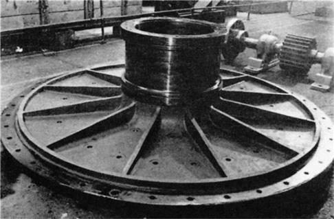
Also known as trunnion heads, they may be of nodular or gray cast iron for diameters less than about 1 m; larger heads are constructed from cast steel, which is relatively light and can be welded. The heads are ribbed for reinforcement and may be flat, slightly conical, or dished. They are machined and drilled to fit shell flanges (Figure 7.7).
Trunnions and Bearings
The trunnions are made from cast iron or steel and are spigoted and bolted to the end plates, although in small mills they may be integral with the end plates (see also Anon., 1990). They are highly polished to reduce bearing friction. Most trunnion bearings are rigid high-grade iron castings with 120–180° lining of white metal in the bearing area, surrounded by a fabricated mild steel housing, which is bolted into the concrete foundations (Figure 7.8).

The bearings in smaller mills may be grease lubricated, but oil lubrication is favored in large mills, via motor-driven oil pumps. The effectiveness of normal lubrication protection is reduced when the mill is shut down for any length of time, and many mills are fitted with manually operated hydraulic starting lubricators, which force oil between the trunnion and trunnion bearing, preventing friction damage to the bearing surface on starting by re-establishing the protecting film of oil (Figure 7.9).

Drive
Tumbling mills are most commonly rotated by a pinion meshing with a girth ring bolted to one end of the machine (Figure 7.10). The pinion shaft is either coupled directly or via a clutch to the output shaft of a slow-speed synchronous motor, or to the output shaft of a motor-driven helical or double helical gear reducer. In some mills, electrical thyristors and/or DC motors are used to give variable speed control. Very large mills driven by girth gears require two motors, each driving separate pinions, with a complex load sharing system balancing the torque generated by the two motors. (See also Knecht, 1990.)

The larger the mill, the greater are the stresses between the shells and heads and the trunnions and heads. In the early 1970s, maintenance problems related to the application of gear and pinion and large speed reducer drives on dry grinding cement mills of long length drove operators to seek an alternative drive design. As a result, a number of gearless drive (ring motor) cement mills were installed and the technology became relatively common in the European cement industry.
The gearless drive design features motor rotor elements bolted to a mill shell, a stationary stator assembly surrounding the rotor elements, and electronics converting the incoming current from 50/60 Hz to about 1 Hz. The mill shell actually becomes the rotating element of a large low speed synchronous motor. Mill speed is varied by changing the frequency of the current to the motor, allowing adjustments to the mill power draw as ore grindability changes.
The gearless drive design was not applied to the mills in the mineral industry until 1981 when the then-world’s largest ball mill, 6.5 m diameter and 9.65 m long driven by a 8.1 MW motor, was installed at Sydvaranger in Norway (Meintrup and Kleiner, 1982). A gearless drive SAG mill, 12 m diameter and 6.1 m length (belly inside liners) with a motor power of more than 20 MW, went into operation at Newcrest Mining’s Cadia Hill gold and copper mine in Australia, with a throughput of over 2,000 t h−1 (Dunne et al., 2001). Motor designs capable of 35 MW have been reported (van de Vijfeijken, 2010).
The major advantages of the gearless drive include: variable speed capacity, removal of limits of design power, high drive efficiency, low maintenance requirements, and less floor space for installation.
Liners
The internal working faces of mills consist of renewable liners, which must withstand impact, be wear-resistant, and promote the most favorable motion of the charge. Rod mill ends have plain flat liners, slightly coned to encourage the self-centering and straight-line action of rods. They are made usually from manganese or chrome-molybdenum steels, having high impact strength. Ball mill ends usually have ribs to lift the charge with the mill rotation. The ribs prevent excessive slipping and increase liner life. They can be made from white cast iron, alloyed with nickel (Ni-hard), other wear-resistant materials, and rubber (Durman, 1988). Trunnion liners are designed for each application and can be conical, plain, with advancing or retarding spirals. They are manufactured from hard cast iron or cast alloy steel, a rubber lining often being bonded to the inner surface for increased life.
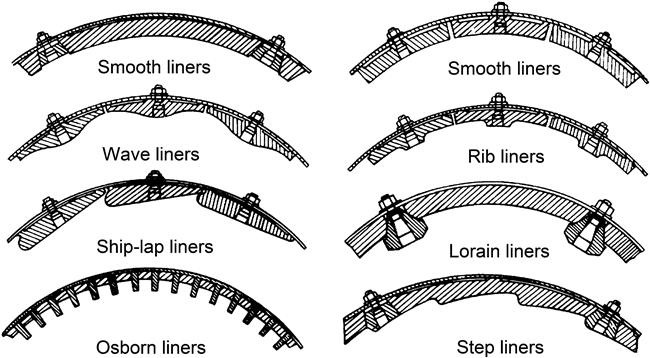
Shell liners have an endless variety of lifter shapes. Smooth linings result in much abrasion, and hence a fine grind, but with associated high metal wear. The liners are therefore generally shaped to provide lifting action and to add impact and crushing. From a survey (Wei and Craig, 2009), the most common shapes were wave, rib, step, and Osborn (Figure 7.11). The liners are attached to the mill shell and ends by forged steel countersunk liner bolts.
Rod mill liners are generally of alloyed steel or cast iron, and of the wave type, although Ni-hard step liners may be used with rods up to 4 cm in diameter. Lorain liners consist of high carbon rolled steel plates held in place by manganese or hard alloy steel lifter bars. Ball mill liners may be made of hard cast iron when balls of up to 5 cm in diameter are used, but otherwise cast manganese steel, cast chromium steel, or Ni-hard are used.
Efforts to prolong liner life are constantly being made. With the lost production cost associated with shut-downs for replacing liners, the trend is toward selecting liners that have the best service life and least relining down-time (Orford and Strah, 2006).
Rubber liners and lifters have supplanted steel at some operations, particularly in ball mills. They have been found to be longer lasting, easier and faster to install, and their use results in a significant reduction of noise level. In primary grinding applications with severe grinding forces, the higher wear rate of rubber tends to inhibit its use. Rubber lining may have drawbacks in processes requiring the addition of flotation reagents directly into the mill, or temperatures exceeding 80°C. They are also thicker than their steel counterparts, which reduces mill capacity, a potentially important factor in small mills. There are also important differences in design aspects between steel and rubber linings (Moller and Brough, 1989). A combination of rubber lifter bars with steel inserts embedded in the face, the steel providing the wear resistance and the rubber backing cushioning the impacts, is a compromise design (Moller, 1990).
A different concept is the magnetic liner. Magnets keep the lining in contact with the steel shell and the end plates without using bolts, while the ball “scats” in the charge and any magnetic minerals are attracted to the liner to form a 30–40 mm protective layer, which is continuously renewed as it wears.
Mill Feeders
The type of feeding arrangement used on the mill depends on whether the grinding is done in open or closed circuit and whether it is done wet or dry. The size and rate of feed are also considerations. Dry mills are usually fed by some sort of vibratory feeder. Three types of feeder are in use in wet-grinding mills. The simplest form is the spout feeder (Figure 7.12), consisting of a cylindrical or elliptical chute supported independently of the mill, and projecting directly into the trunnion liner. Material is fed by gravity through the spout to the mills. They are often used for feeding rod mills operating in open circuit or mills in closed circuit with hydrocyclone classifiers.

An alternative to a spout feeder, drum feeders (Figure 7.13) may be used when headroom is limited. The mill feed enters the drum via a chute or spout and an internal spiral carries it into the trunnion liner. The drum also provides a convenient method of adding grinding balls to a mill.

Combination drum-scoop feeders (Figure 7.14, see also Figure 7.2) are generally used for wet grinding in closed circuit with a spiral or rake classifier. New material is fed directly into the drum, while the scoop picks up the classifier sands for regrinding. Either a single or a double scoop can be used, the latter providing an increased feed rate and more uniform flow of material into the mill; the counter-balancing effect of the double-scoop design serves to smooth out power fluctuation and it is normally incorporated in large-diameter mills. Scoop feeders are sometimes used in place of the drum-scoop combination when mill feed is in the fine-size range.

7.2.4 Types of Tumbling Mill
Rod Mills
These mills can be considered as either fine crushers or coarse grinding machines. They are capable of taking feed as large as 50 mm and making a product as fine as 300 µm, reduction ratios (F80:P80) normally being in the range 15:1–20:1. They are often preferred to fine crushing machines when the ore is “clayey” or damp, thus tending to choke crushers. They are still to be found in older plants but are often replaced upon modernization (e.g., Leung et al., 1992) and are now relatively rare (Wei and Craig, 2009).
The distinctive feature of a rod mill is that the length of the cylindrical shell is between 1.5 and 2.5 times its diameter (Figure 7.15). This ratio is important because the rods, which are only a few centimeters shorter than the length of the shell, must be prevented from turning so that they become wedged across the diameter of the cylinder (a rod tangle). The ratio must not, however, be so large for the maximum diameter of the shell in use that the rods deform and break. Since rods longer than about 6 m will bend, this establishes the maximum length of the mill. Thus, with a mill 6.4 m long the diameter should not be over 4.57 m. Rod mills of this size have seen use, driven by 1,640 kW motors (Lewis et al., 1976).

Rod mills are classed according to the nature of the discharge. A general statement can be made that the closer the discharge is to the periphery of the shell, the quicker the material will pass through and less overgrinding will take place.
Center peripheral discharge mills (Figure 7.16) are fed at both ends through trunnions and discharge the ground product through circumferential ports at the center of the shell. The short path and steep gradient give a coarse grind with a minimum of fines, but the reduction ratio is limited. This mill can be used for wet or dry grinding and has found its greatest use in the preparation of specification sands, where high tonnage rates and an extremely coarse product are required.

End peripheral discharge mills (Figure 7.17) are fed at one end through the trunnion, discharging the ground product from the other end of the mill by means of several peripheral apertures into a close-fitting circumferential chute. This type of mill is used mainly for dry and damp grinding, where moderately coarse products are involved.

The most widely used type of rod mill in the mining industry is the trunnion overflow (Figure 7.18), in which the feed is introduced through one trunnion and discharges through the other. This type of mill is used only for wet grinding and its principal function is to convert crushing-plant product into ball mill feed. A flow gradient is provided by making the discharge (overflow) trunnion diameter 10–20 cm larger than that of the feed opening. The discharge trunnion is often fitted with a spiral (trommel) screen to remove tramp material.

Rod mills are charged initially with a selection of rods of assorted diameters, the proportion of each size being calculated to approximate to a seasoned or equilibrium charge. A seasoned charge will contain rods of varying diameters, ranging from fresh replacements to those that have worn down to such a size as to warrant removal. Actual diameters in use range from 25 to 150 mm. The largest diameter should be no greater than that required to break the largest particle in the feed. A coarse feed or product normally requires larger rods. Provided the large feed particles are broken, the smaller the rods the larger is the total surface area and hence the greater is the size reduction. Generally, rods should be removed when they are worn down to about 25 mm in diameter or less, depending on the application, as small ones tend to bend or break, filling the mill with “scats”. High carbon steel rods are used as they are hard, and break rather than warp when worn, and so do not entangle with other rods.
Optimum grinding rates are obtained with about 45% charge filling (see Section 7.2.2). Overcharging results in inefficient grinding and increased liner and rod consumption; reduced rod consumption may indicate an economic optimum at less than 45% filling. Rod consumption varies widely with the characteristics of the mill feed, mill speed, rod length, and product size; it is normally in the range 0.1–1.0 kg of steel per ton of ore for wet grinding, being less for dry grinding.
Rod mills are normally run at between 50% and 65% of the critical speed, so that the rods cascade rather than cataract; many operating mills have been sped up to close to 80% of critical speed without any reports of excessive wear (McIvor and Finch, 1986). The feed pulp density is usually between 65% and 85% solids by weight, finer feeds requiring lower pulp densities. The grinding action results from line contact of the rods on the ore particles; the rods tumble in essentially a parallel alignment, and also spin, thus acting rather like a series of crushing rolls. The coarse feed tends to spread the rods at the feed end, so producing a wedge- or cone-shaped array. This increases the tendency for grinding to take place preferentially on the larger particles, thereby producing a minimum amount of extremely fine material (Figure 7.19). This selective grinding gives a product of relatively narrow size range, with little oversize or slimes. Rod mills are therefore suitable for preparation of feed to gravity concentrators, certain flotation processes with slime problems, magnetic cobbing, and ball mills. They are nearly always run in open circuit because of this controlled size reduction.

Ball Mills
The final stages of primary comminution are performed in tumbling mills using steel balls as the grinding medium, and so are designated “ball mills.” A typical ball mill setup is shown in Figure 7.20.

Since balls have a greater surface area per unit weight than rods, they are better suited for fine grinding. The term ball mill is restricted to those having a length to diameter ratio of 2 to 1 and less. Ball mills in which the length to diameter ratio is between 3 and 5 are designated tube mills. The latter are sometimes divided into several longitudinal compartments, each having a different charge composition; the charges can be steel balls or rods, or pebbles, and they are often used dry to grind cement clinker, gypsum, and phosphate. Tube mills having only one compartment and a charge of hard, screened ore particles as the grinding medium are known as pebble mills. They have the advantage over ball mills when iron contamination needs to be avoided. Since the weight of pebbles per unit volume is about 35–55% of that of steel balls, and as the power input is directly proportional to charge weight, the power draw and capacity of pebble mills are correspondingly lower (see Section 7.2.2). Thus in a given grinding circuit, for a certain feed rate, a pebble mill would be much larger than a ball mill, with correspondingly higher capital cost. The increment in capital cost might be justified by reduction in operating cost attributed to the lower cost of the grinding medium, provided this is not offset by higher energy cost per ton of finished product (Lewis et al., 1976).
Ball mills are also classified by the nature of the discharge. They may be simple trunnion overflow mills, operated in open or closed circuit, or grate discharge (low-level discharge) mills. The latter type is fitted with discharge grates between the cylindrical mill body and the discharge trunnion. The pulp can flow freely through the openings in the grate and is then lifted up to the level of the discharge trunnion (Figure 7.21). These mills have a lower pulp level than overflow mills, thus reducing the residence time of particles in the mill. Consequently, little overgrinding takes place and the product contains a large fraction of coarse material, which is returned to the mill by some form of classifying device. Closed-circuit grinding, with high circulating loads, produces a closely sized end product and a high output per unit volume compared with open circuit grinding. Grate discharge mills usually take a coarser feed than overflow mills and are not required to grind so finely, the main reason being that with many small balls forming the charge, the grate open area plugs very quickly. The trunnion overflow mill is the simplest to operate and is used for most ball mill applications, especially for fine grinding and regrinding. Energy consumption is said to be about 15% less than that of a grate discharge mill of the same size, although the grinding efficiencies of the two mills are similar (Lewis et al., 1976).

The trend in recent years has been to use fewer comminution machines per grinding line with the result that units have increased considerably in size and thus capacity. For example, in the 1980s, the largest operating ball mill was 5.5 m in diameter by 7.3 m in length driven by a 4 MW motor. Today the largest ball mills in operation are over 8 m in diameter utilizing gearless (wrap-around) motors with power output of more than 16 MW.
Grinding in a ball mill is effected by point contact of balls and ore particles and, given time, any degree of fineness can be achieved. The process is completely random—the probability of a fine particle being struck by a ball is the same as that of a coarse particle. The product from an open-circuit ball mill therefore exhibits a wide range of particle size, and overgrinding of at least some of the ore can be a problem. Closed-circuit grinding in mills providing low residence time for the particles is almost always used in the last stages to overcome this.
Several factors influence the efficiency of ball mill grinding. The pulp density of the feed should be as high as possible, consistent with ease of flow through the mill. It is essential that the balls are coated with a layer of ore; too dilute a pulp increases metal-to-metal contact, giving increased steel consumption and reduced efficiency. Ball mills should operate between 65% and 80% solids by weight, depending on the ore. The viscosity of the pulp increases with the fineness of the particles, therefore fine-grinding circuits may need lower pulp densities. The major factors affecting the pulp rheology and its effects on grinding circuits have been discussed by a number of researchers (Klimpel, 1984; Kawatra and Eisele, 1988; Moys, 1989; Shi and Napier-Munn, 2002; He et al., 2004; Pax, 2012). It was found that not only the viscosity of the pulp but also the rheological type, Newtonian or non-Newtonian, would affect ball milling performance. An extreme case of high viscosity slurry is grinding fibrous ore particles where mills have to operate at low %solids.
The efficiency of grinding depends on the surface area of the grinding medium. Thus, balls should be as small as possible and the charge should be graded such that the largest balls are just heavy enough to grind the largest and hardest particles in the feed. A seasoned charge will consist of a wide range of ball sizes and new balls added to the mill are usually of the largest size required. Undersize balls leave the mill with the ore product and can be removed by passing the discharge through trommel screens or by magnets mounted near the discharge trunnion. Various formulae have been proposed for the required ratio of ball size to ore size, none of which is entirely satisfactory. The correct sizes are often determined by trial and error, primary grinding usually requiring a graded charge of 10-5 cm diameter balls, and secondary grinding requiring 5-2 cm. Concha et al. (1988) have developed a method to calculate ball mill charge by using a grinding circuit simulator with a model of ball wear in a tumbling mill.
Segregation of the ball charge within the mill is achieved in the Hardinge mill (Figure 7.22). The conventional drum shape is modified by fitting a conical section, the angle of the cone being about 30°. Due to the centrifugal force generated, the balls are segregated so that the largest are at the feed end of the cone, that is, the largest diameter and greatest centrifugal force, and the smallest are at the discharge. By this means, a regular gradation of ball size and of size reduction is produced.

There are also non-spherical shapes of grinding media such as Doering Cylpebs. The Cylpebs are slightly tapered cylindrical grinding media with length equaling diameter, and all the edges being rounded (Figure 7.23). They are available in sizes from 85 mm×85 mm to 8 mm×8 mm. Because of their geometry, these grinding media have greater surface area than balls of the same mass. For instance, Cylpebs with a diameter to height ratio of unity have 14.5% more surface area than balls. It was thus supposed that these grinding media would produce more fines in a grinding mill than balls. However, in laboratory tests it was found that the comparison depended on what was held constant between the two media types: mass, size distribution, or surface area (Shi, 2004).

Grinding balls are usually made of forged or rolled high-carbon or alloy steel, cast alloy steel and some of white iron (Rajagopal and Iwasaki, 1992). Consumption varies between 0.1 and as much as 1 kg t−1 of ore depending on hardness of ore, fineness of grind, and medium quality. Medium consumption can be a high proportion, sometimes as much as 40% of the total milling cost, so is an area that often warrants special attention. Good quality grinding media may be more expensive, but may be economic due to lower wear rates. Finer grinding may lead to improved metallurgical efficiency, but at the expense of higher grinding energy and media consumption. Therefore, particularly with ore of low value, where milling costs are crucial, the economic limit of grinding has to be carefully assessed (Chapter 1).
As the medium consumption contributes significantly to the total milling cost, great effort has been expended in the study of medium wear. Three wear mechanisms are generally recognized: abrasion, corrosion, and impact (Rajagopal and Iwasaki, 1992). Abrasion refers to the direct removal of metal from the grinding media surface. Corrosion refers to electrochemical reactions with oxygen, sometimes enhanced by galvanic effects with sulfide minerals (see Chapter 12); continual removal of oxidation products by abrasion means the fresh surface is always being exposed to such reactions. Impact wear refers to spalling, breaking, or flaking (Misra and Finnie, 1980; Gangopadhyay and Moore, 1987). Operational data show that abrasion is the major cause of metal loss in coarse (primary) grinding, with more corrosion occurring in finer regrinding (Dunn, 1982; Dodd et al., 1985). Corrosion products (iron oxy-hydroxides) can be detrimental to flotation and has led to the use of “inert” media, including high chrome balls, but also ceramic and other non-iron media (see Chapter 12).
Attempts have been extended to predict media wear by developing a model incorporating the abrasive, corrosive, and impact wear mechanisms (Radziszewski, 2002). An example is the following empirical ball wear model for forged carbon steel based on fitting data from 46 Peruvian mills to ore hardness, pulp acidity and particle top size given by Rabanal and Guzmán (2013):
(7.10)
 (7.10)
where ΩE is the energy-corrected ball wear rate, g per kWh, dR is the diameter of the largest balls in the mill (the recharge size), mm, ![]() is the linear wear rate of balls, µm per kWh t−1, Ai is the Bond abrasion index determined in a laboratory test (unitless), F80 is the feed 80% passing size of the ore, µm, and pH is the water acid/base measurement of the mill pulp.
is the linear wear rate of balls, µm per kWh t−1, Ai is the Bond abrasion index determined in a laboratory test (unitless), F80 is the feed 80% passing size of the ore, µm, and pH is the water acid/base measurement of the mill pulp.
The charge filling in a ball mill is about 30–45% of the internal volume of the mill, about 40% of this being void space. As discussed in Section 7.2.2, the reason is the power draw passes through a maximum at about a filling of 45%. Given the cost of media it may be economic to operate at the lower end of the filling range, even at the expense of a loss in energy efficiency, the same point noted for rod mills.
Ball mills are often operated at higher speeds than rod mills, so that the larger balls cataract and impact on the ore particles. The work input to a mill increases in proportion to the speed, and ball mills are run at as high a speed as is possible without centrifuging. Normally this is 70–80% of the critical speed.
Autogenous/Semi-autogenous Mills
The highest throughput grinding circuits in the mining industry use autogenous grinding (AG) or semi-autogenous grinding (SAG) mills. An AG mill is a tumbling mill that uses the ore itself as grinding media. The ore must contain sufficient competent pieces to act as grinding media and preferably be high specific gravity (s.g.) which, for example, favors AG milling of iron ores (s.g. 4 vs. 2.7 for high silicate ores). A SAG mill is an autogenous mill that uses steel balls in addition to the natural grinding media. A typical setup is shown in Figure 7.24. The ball charges in SAG mills have generally been most effective in the range of 4–15% of the mill volume, including voids. As noted in Section 7.2.2 there is a case to increase ball charge to increase power draw. In South African practice SAG mills can have a ball charge as high as 35% of mill volume (Powell et al., 2001).

The first paper describing ore as grinding media was delivered to the American Institute of Mining and Metallurgical Engineers in 1908. In the early 1930s, Alvah Hadsel installed the Hadsel crushing and pulverizing machine, which was later improved by the Hardinge Company and was called the Hardinge Hadsel Mill. Early deployment of AG mills can be attributed primarily to a need in the iron ore industry to economically process large quantities of ore in the late 1950s. The high density of iron ores compared to many others probably favored AG milling. Non-ferrous operations (mostly copper and gold) utilized AG milling to a lesser extent before recognizing that SAG milling was better able to handle a variety of ore types. By December 2000, at least 1075 commercial AG/SAG mills had been sold worldwide with a total installed power exceeding 2.7 GW. SAG mills installed in Chile now regularly exceed 100,000 tons per day treated in a single mill.
AG/SAG mills usually replace the final two stages of crushing (secondary and tertiary) and rod milling of the traditional circuit (Chapter 6). This gives some advantages over the traditional circuit: lower capital cost, ability to treat a wide range of ore type including sticky and clayey feeds, relatively simple flowsheets, large size of available equipment, lower manpower requirements, and reduced steel consumption (noting that these mills replace some crushing/rod milling stages). The use of AG/SAG milling has grown to the point where many existing plants are retrofitting them, whilst new plants rarely consider a design that does not include them. This may not continue in the future, as new technologies such as fine crushing, high pressure grinding rolls, and ultra fine grinding (stirred milling) offer alternative flowsheet options (Erikson, 2014).
A schematic of various sections of the autogenous grinding mill is shown in Figure 7.25. AG or SAG mills are defined by the aspect ratio of the mill shell design and the product discharge mechanism. The aspect ratio is defined as the ratio of diameter to length. Aspect ratios generally fall into three groups: high aspect ratio mills where the diameter is 1.5–3 times of the length, “square mills” where the diameter is approximately equal to the length, and low aspect ratio mills where the length is 1.5–3 times that of the diameter. Although Scandinavian and South African practice favors low aspect ratio AG/SAG mills, in North America and Australia the mills are distinguished by high aspect ratios. The largest SAG mills are up to 12 m in diameter by 6.1 m length (belly inside liners), driven by a motor power of more than 20 MW. Many high aspect ratio mills, particularly the larger diameter units, have conical rather than flat ends. Attention should therefore be given to the mill length definition.

Inside the milling chamber the mill is lined with wearing plates held by lifter bars bolted to the shell. Lifter bars are essential to reduce slippage of the mill load, which causes rapid wear of the liners and also impairs the grinding action. The shape and geometry of the lifter bars, particularly the height and the face angle, have a significant influence on milling performance and wear rates.
The grate, as shown in Figure 7.25, is used to hold back the grinding media and large rock pieces and allow fine particles and slurry to flow through. Shapes of the grate apertures can be square, round, or slotted, with size varying from 10 to 40 mm. In some installations there are large holes varying from 40 to 100 mm in the grate, designated as pebble ports, which allow pebbles to be extracted and crushed (to ca. 12–20 mm) prior to recirculation to the mill. The total open area of the grate is ca. 2–12% of the mill cross-sectional area.
The slurry of particles smaller than the grate apertures discharges into the pulp lifter chambers. The pulp lifters, which are radially arranged, as shown in Figure 7.25, rotate with the mill and lift the slurry into the discharge trunnion and out of the mill. Each pulp lifter chamber is emptied before its next cycle to create a gradient across the grate for slurry transportation from the milling chamber into the pulp lifter chambers.
There are two types of pulp lifter design: radial and curved (also known as spiral, refer to Figure 7.26). The radial (or straight type) is more common in the mineral processing industry.

While the major portion of the slurry passing through the grate is discharged from the mill via the discharge trunnion, a proportion of the slurry in the pulp lifter chamber flows back into the mill as the mill rotates. This flow-back process often leads to higher slurry holdup inside the mill, and may sometimes contribute to the occurrence of “slurry pooling”, which has adverse effects on the grinding performance (Morrell and Kojovic, 1996). To improve the slurry transportation efficiency of the pulp lifters, particularly where slurry pooling limits capacity, a new concept of a Twin Chamber Pulp Lifter was developed (Latchireddi and Morrell, 2003, 2006) and first tested in a bauxite plant (Alcoa’s 7.7 m diameter mill) in Western Australia (Morrell and Latchireddi, 2000). In this design, the slurry first enters the section exposed to the grate, the transition chamber, and then flows into the lower section, the collection chamber, which is not exposed to the grate. This mechanism prevents the pulp from flowing backward into the mill, which can significantly increase the capacity of the mill. The Turbo Pulp Lifter from Outotec is a similar concept. DEM analysis has helped refine lifter design to minimize pulp flow back. With curved pulp lifters the rotation of the mill cannot be reversed (used to extend liner life); in consequence asymmetric liner profiles are employed designed to resist wear on the leading side.
AG/SAG milling may be wet or dry. Dry AG mills were once common in iron ore grinding. They have more workplace environmental problems (dust), do not handle materials containing clay well, and are more difficult to control than wet mills. In certain talc and mica grinding applications dry SAG mills are operated.
AG/SAG mills can handle feed ore as large as 200 mm, normally the product of the primary crusher or the run-of-mine ore, and achieve a product of 0.1 mm in one stage. The particle size distribution of the product depends on the characteristics and structure of the ore being ground. The main mechanism of comminution in AG/SAG mills is considered to be abrasion and impact. Due to the relatively gentle comminution action, fractures in rock composed of strong equidimensional mineral grains in a weaker matrix are principally at the grain or crystal boundaries. Thus the product sizing is predominantly around the region of grain or crystal size. This is generally desirable for subsequent mineral separation as the wanted minerals are liberated with minimal overgrinding, and the grains keep their original prismatic shape more intact. A pilot plant study was made of the liberation characteristics of a nickel sulfide ore with full autogenous and semi-autogenous milling conditions. The mill products were sized and assayed and then analyzed by QEMSEM. Evidence indicated that selective breakage was occurring in both cases, leading to preferential liberation of sulfides (Wright et al., 1991).
Investigations have shown that ores ground autogenously may float faster than if ground with steel media (Forssberg et al., 1993). Grinding with steel media can suppress the floatability of minerals, due to release of iron oxidation products into the slurry (Chapter 12).
In comparison with high aspect ratio mills, SAG mills in the gold mines of South Africa (locally known as “run-of-mine” mills, or ROM mills) are low aspect ratio (largest mills are 4.88 m diameter and up to 12.2 m in length), and are normally operated at high ball charge (up to 35%), high total filling (up to 45%), and high speeds (up to 90% critical). They are often operated in a single stage of grinding to produce final product of 75–80% passing 75 µm from a feed top size around 200 mm, but the mill throughput is relatively low. The initial cost of low aspect ratio AG/SAG mills is less than high aspect ratio mills, but they consume more power per ton of product. The development of the different operating practice in South Africa occurred for historical rather than operational reasons. The ROM mills evolved from pebble tube mills used for fine secondary grinding that were converted to primary mills by directing the full run-of-mine feed to them.
The influence of feed size and hardness on AG or SAG mill operation is more significant than that on rod mill or ball mill operation. In rod or ball mills, the mass of the media accounts for approximately 80% of the total mass of the charge and dominates both the power draw and the grinding performance of the mills (see Section 7.2.2). In SAG mills a significant proportion (or all of it, in AG mills) of the grinding media derives from the feed ore. Any change in the feed size distribution and hardness will therefore result in a change of the breakage characteristics, and the mill charge level will be changed, which affects the mill power draw. As a result, the measured AG/SAG mill power draw often varies widely with time. This is one of the significant differences in operation between the AG/SAG mill and the rod/ball mill, power draw of the latter being relatively stable. In response to the variation in feed size and hardness, the mill feed rate has to be changed. At BHP-Billiton OK Tedi Mine (Papua New Guinea), the ore hardness varied between 5 and 16 kWh t−1, and the throughput to the 9.8 m by 4.3 m (7.5 MW) SAG mill could vary between 700 and 3,000 t h−1 (Sloan et al., 2001). The effects of feed size and hardness on AG/SAG mill operation have been discussed (Bouajila et al., 2001; Hart et al., 2001; Morrell and Valery, 2001).
The AG and SAG mills respond in a different manner to feed size changes. In an AG mill sufficient numbers of large rocks need to be provided to maintain a high enough frequency of breakage collisions. In general, AG mill performance is better with coarser feeds, up to 200 mm. In SAG mills, however, ball charge tends to dominate rock breakage, and the contribution of rock grinding media will decrease (see Section 7.2.2). The coarser feed rocks provide less of a grinding media role and will instead provide a rock burden that requires to be ground. By reducing the feed size in these circumstances, the grinding burden will be reduced (Napier-Munn et al., 1996).
Since the feed size and hardness exert an important influence on AG/SAG mill performance, there are incentives to take account of the mine to mill operation through controlling blasting practices, mining methods, run-of-mine stockpiling, partial or fully secondary crushing, and selective pre-screening of AG/SAG mill feed. The mine-to-mill exercise has resulted in significant benefits to mining companies in terms of improving AG/SAG mill throughput, energy consumption, and grinding product size distribution (Scott et al., 2002).
The effect of feed characteristics on AG/SAG mills also differs from that on high pressure grinding rolls (Chapter 6). HPGRs are close to constant tonnage units: changes in feed characteristics will affect the power draw of the HPGR but tonnage remains fairly consistent compared to AG/SAG mills. This provides for greater circuit stability, and is a contributing reason to the growing interest in using HPGR technology (Lichter, 2014).
7.2.5 Motor Selection for Tumbling Mills
The choice of motor is dictated by the amount of power required, and whether or not the mill requires a variable speed capability. The efficiency of a particular drive dictates the economics of each motor type.
Three types of electric motors are commonly used to drive large tumbling mills:
Gearless
The largest mills, any requiring over 18 MW of power output, are almost always driven by gearless drives where the rotor of the motor is mounted to an external circumferential flange of the mill and the stationary stator of the motor is mounted securely to a foundation wrapped around the mill flange. Because of the large stator structure, these drives are sometimes called wrap-around or ring motors. Gearless drives operate at the same speed that the mill is turning and require a sophisticated drive control system that includes an inherent variable speed capability.
Synchronous
Widely used in North and South America, the synchronous motor is mounted beside one end of a mill and is connected to the mill via gears. The motor drives a pinion, which is a small geared shaft that connects to the bull gear that wraps around the mill circumference on a flange at one end of the mill. Synchronous motors derive their name from the way that the motor speed synchronizes with the waveform of the electric alternating current (AC) phases. This means the motor operates at a fixed speed in its simplest form. A maximum of two motors can be connected to the mill’s bull gear via separate pinions, called a twin-pinion arrangement, developed for large mills (>5.5 m).
Wound-rotor Induction
Common in Australia and Africa, the wound-rotor motor also uses a gear system to transmit energy to the mill. It operates at a higher motor speed than the synchronous motor and needs an additional mechanical gear-box to reduce the motor shaft speed to the pinion speed needed to drive the mill. A slip energy recovery system is commonly used to permit modest speed adjustments when the motor is operating near its design speed. Wound-rotor induction motors can also be in a twin-pinion arrangement.
It is often desirable to adjust the speed at which a tumbling (primarily AG/SAG) mill operates; in such a circumstance, the mill drive system design must include a mechanism to achieve a variable speed capability (Barratt et al., 1999). Both the synchronous and wound-rotor induction motors can be made fully variable speed if the electric AC waveforms delivered to them by the drive electrical system are modified. A variety of technologies can be used to adapt the AC waveform. Two common variable speed drives for synchronous motors are the cycloconverter and the load commutating inverter (Grandy et al., 2002; von Ow, 2009).
The choice of motor and drive type is dictated first by the motor size (von Ow, 2009):
• Single-pinion drives are available up to 9 MW
• Twin-pinion arrangements of synchronous and wound-rotor induction motors are available in sizes ranging from 18 MW down to 6 MW
• Gearless drive systems are available in sizes ranging from 30 MW down to 12 MW
The electrical efficiency of fixed speed synchronous motors is greater than fixed speed wound-rotor induction motors, but the initial cost is higher. The gearless motor has a higher efficiency than a variable speed synchronous drive, which has a higher efficiency than a fully variable speed wound-rotor induction drive. The initial capital cost, however, and installation time favor the wound-rotor induction motor, followed by the synchronous motor, with the gearless being the most expensive motor with the longest installation time. A financial and plant power grid evaluation is often used to choose between motor options.
7.2.6 Sizing Tumbling Mills
Tumbling mills are rated by power rather than capacity, since the capacity is determined by many factors, such as the grindability, determined by laboratory testing (Chapter 5), and the reduction in size required.
Rod and Ball Mills
The specific energy needed for a certain required capacity may be estimated by the use of Bond’s equation, written here as:
(7.11)
where W is the specific energy consumption of the mill, kWh t−1; Wi is the work index measured in a laboratory mill, kWh t−1; F80 and P80 are, respectively, the circuit feed and product 80% passing sizes, µm; and EFx is the product of the Rowland efficiency factors applicable to a grinding stage. The Rowland efficiency factors dependent on the size of mill, size and type of media, type of grinding circuit, etc. (Rowland and Kjos, 1980; Rowland, 1982; King, 2012). The power required (in kW) is then given by W×T, where T is the throughput tonnage (t h−1) (see Example 7.2).
Example 7.2
Using the Bond equation, select the size of ball mill in closed circuit with a cyclone for the following conditions: F80=600 µm, P80=110 µm, Wi=10.5 kW t−1, T=150 t h−1.
Solution
Note that the P80 is the circuit product (i.e., cyclone overflow) and circulating load is assumed to be 250% (Rowlands, 1982). Solving for W, and ignoring efficiency factors (for simplicity) then:
Therefore the power draw P is;
The size of mill is then selected from either a calibrated power model (Section 7.2.2) or, more generally, from manufacturer’s data, such as in the table below (Table ex 7.2).
Table ex 7.2
Ball Mill Specifications (overflow discharge, 40% charge filling: see Rowlands, 1982)
| Diameter (m) | Length (m) | Ball Size (mm) | Mill Speed (% critical) | Charge Weight (t) | Mill Power (kW) |
| 3.96 | 3.96 | 50 | 71.7 | 82.8 | 843 |
| 4.12 | 3.96 | 64 | 71.7 | 89.4 | 945 |
| 4.27 | 4.27 | 64 | 70.7 | 104 | 1093 |

The mill (4.12 m×3.96 m) meets the target power.
AG/SAG Mills
Extensive testing is being conducted for sizing autogenous or semi-autogenous mills because of the lack of equivalent methodology as represented in the Bond approach for rod and ball mills. Pilot scale testing of ore samples, more specifically for an autogenous mill where the grinding medium is also the material to be ground and consequently a variable itself, has become a necessity in assessing the feasibility of AG/SAG milling, predicting the energy requirement, flowsheet, and product size (Rowland, 1987; Mular and Agar, 1989; Mosher and Bigg, 2001).
The use of energy-based or mathematical modeling and simulation can help reduce the cost of the pilot tests by narrowing the choice of processing route at the pre-feasibility stage. This approach includes collection of a large quantity of representative ore samples that are typically drill cores or samples taken throughout the ore body. The rock breakage characterization data are obtained through standard laboratory tests such as the drop-weight impact and tumbling tests (Napier-Munn et al., 1996), SAGDesign tests (Starkey et al., 2006), the MacPherson autogenous mill work index test (MacPherson, 1989; Mosher and Bigg, 2001) and more recently, the Rotary Breakage Tester (Shi et al., 2009). The breakage characteristics of the ore are compared with extensive databases of ore types and plant performance, which provides an indication of the ore’s relative strength and amenability to processing in various circuit configurations. Following pilot scale tests, computer simulation software such as JKSimMet (Napier-Munn et al., 1996) is used to scale-up to the full-size plant. There are other computer software available for plant simulation, such as MODSIM developed by King and co-workers (Ford and King, 1984), USIM-PAC (Evans et al., 1979), and CEET (Comminution Economic Evaluation Tool) (Dobby et al., 2001; Starkey et al., 2001). Even in the absence of pilot data, energy-based models or simulation can still provide reasonably accurate prediction of full-scale plant performance.
The cost of a thorough pilot testing or standard testwork program can be prohibitive, particularly for deposits with highly variable ore types. Instead of collecting large representative samples, a large number of small quantity drill core samples, representatives of the different geological domains of the deposit, are collected throughout the ore body to be characterized by simpler tests such as the SPI test (SAG Power Index) or abbreviated versions of the standard laboratory tests, such the SMC (Morrell, 2004), the RBT Lite (JKTech Brochure) or the SVT (Brissette et al., 2014). These tests are recognized to be geometallurgical tests (Chapter 17). Geometallurgy methodology is increasingly used as a standard in both design and production forecasting of AG/SAG circuits worldwide, giving a much better understanding of the ore response to milling for any deposit.
7.3 Stirred Mills
The concept of stirred milling dates back to about 1928 (Stehr, 1988) when the idea of using “an agitator and spherical grinding media” was presented. In 1948 DuPont introduced the “sand mill” for pigment grinding. Stirred milling found applications in multiple fine to ultrafine grinding applications from pharmaceuticals to industrial minerals. Starting about two decades ago, stirred milling has become more prevalent in milling applications, corresponding to the increase in processing of more complex fine-grained ores demanding liberation grinds of 10 μm and less (Underle et al., 1997; Ellis and Gao, 2002).
The common stirred mills in mineral processing are of two types: those that operate at low stirrer speed where gravity plays a role, the Metso Vertimill®, and the Eirich TowerMill®; and high-speed stirred mills which fluidize the pulp, the Metso Stirred Media Detritor (SMD®), the Xstrata IsaMill®, the FLSmidth VXP® Mill and, since 2012, the Outotec High Intensity Grinding Mill (HIGMill®). The Figure 7.27 shows the increase in installed power of fine grinding technologies in the past 20 years. The application is mainly in regrinding to increase liberation and concentrate grade.

Stirred mills differ from tumbling mills in how grinding energy is transferred to the material being ground. Tumbling mills use both impact and shear (abrasion/attrition) energy in roughly equal measure (Radziszewski and Allen, 2014), while stirred mills use predominately shear energy. For fine grinding, shear is more effective and stirred mills are more energy efficient (use less energy per ton) than tumbling mills when the product P80 is less than about 100 μm (Nesset et al., 2006; Mazzinghy et al., 2012). One simple explanation for this higher energy efficiency is that media impacts (i.e., balls colliding) tend to expel fine particles with the slurry rather than nip and break them (“splash out” effect). While initial applications were in regrinding stirred mills have attracted interest for use in primary grinding circuits.
7.3.1 Power Draw and Stress Intensity
Power Draw
From a review of existing power models for stirred mills, Radziszewski and Allen (2014) proposed that if all grinding is accomplished via shear then grinding power can be represented by the following:
(7.12)
where Pτ is the shear power (W), µ the viscosity of the mill contents (N.s m−2) (for which a relationship was given), ω the angular velocity (rad s−1), and Vτ the “shear volume” (referring to all the shear surface pairs between an impeller and the mill chamber). With appropriate calibration the predicted power matched the measured power for the data of Gao et al. (1996) and Jankovic (1998).
Stress Intensity
This is a measure of the pressure acting on the particles and is fixed during the comminution process as the conditions—grinding media size and density, stirrer speed and slurry density—are normally constant during operation. In the fluidized slurry mills the stress derives mainly from the action of the media, while for lower stirrer speed mills gravity (the weight of the charge) also contributes stress. Expressions for stress intensity have been developed by Kwade et al. (1996) and Jankovic (2001). There is a relationship between stress intensity and product size and an optimum exists that gives maximum size reduction (lowest product P80) and thus is the most energy efficient condition (Jankovic, 2001). As with tumbling mills, the ratio of media size to particle size is of particular significance in optimizing energy consumption (Jankovic, 2003).
7.3.2 Sizing Stirred Mills
Specific grinding energy (kWh t−1) is the key parameter for sizing industrial units. The Bond method, successfully used to size ball mills, for example, is not applicable to stirred milling. Development of testing methodologies is still continuing and in some cases there can be discrepancies in scale-up of 100–300% (Larson et al., 2011). The three most common bench techniques for sizing a stirred grinding mill are the Levin Test, the Metso Jar Ball Mill Test, and the Signature Plot.
Levin Test
This test requires “baseline” data from an operating mill (i.e., feed size, product size, mill tonnage, and total grinding energy consumption). A sample of the baseline reference material is used to calibrate the lab scale mill. The test sample is ground to the same product size as the baseline reference and the number of revolutions required to achieve the target size is recorded. Once calibrated, the energy delivered per revolution is assumed to be the same. Any future material’s specific energy requirements can be estimated by recording the number of revolutions required to achieve a particular target size. The challenge of the method is obtaining high quality baseline data.
Metso Jar Ball Mill Test
This method can be carried out wet or dry in a tumbling grinding mill (8˝ D×10˝ L). Grinding is carried out over several grinding periods (e.g., 10 min and 20 min). Both product size and energy consumption are recorded for each subsequent grinding period. The measured energy is multiplied by 0.65 (VTM factor) and 1.10 (SMD factor) to predict the energy required by a Vertimill® and Stirred Media Detritor, respectively.
Signature Plot Technique
The signature plot takes a 20 kg sample at 50 wt% solids and runs the sample through a test mill. At fixed periods, with a known energy expenditure, a sample is taken to determine the particle size distribution. (See also Chapter 5.) Typically, the method takes either 12 data points or as many until a reduction in size is no longer taking place. This technique has been used for sizing both the Xstrata IsaMill® and the FLSmidth VXP® mill.
Pilot testing of a stirred mill can normally be done with a scale model of the milling technology. Fluidized mills (such as the IsaMill®) have been found to scale up directly to industrial units as long at the test units are 1 L in volume or greater (Karbstein et al., 1996). This is attributed to the fact that the stress intensity responsible for breakage is due to the high speed stirring. Technologies that employ both lower stirring speeds and gravitational stress intensity to induce grinding (such as the Vertimill®) need larger pilot units in order to ensure that the significant gravity stress component is being reproduced.
7.3.3 Mill Types
Stirred milling technologies can be classified by four properties: the orientation of the mill, the shape of the impeller, the mill shell surface, and the speed of the impeller (Figure 7.28).

All mills currently on the market can be described by the combinations in Figure 7.28. For example, a Vertimill® would be a vertical, screw impeller, smooth shell liner, and low speed mill, while an IsaMill® would be a horizontal, disc impeller, smooth surface and high speed mill. Table 7.1 summarizes the features of the available stirred mills. A mill’s orientation tends to be more a plant design factor as horizontal units require more footprint, while vertical units need more head room. The disc and pin impellers are currently associated with the medium to high speed (i.e., the fluidized) technologies, while the screw impeller is associated with the low speed technologies. The selection of a non-smooth liner would be in cases where one wanted to create more shear volume (Radziszewski, 2013).
Table 7.1
Industrial Stirred Mills in Mineral Processing
| Mill Name | IsaMill | Vertmill/TowerMill | Stirred Media Detritor | VXP Mill | HIGMill | |
| Manufacturer | Glencore | Metso/Eirich | Mesto | FLSmidth | Outotec | |
| Description | Orientation | Horizontal | Vertical | Vertical | Vertical | Vertical |
| Impeller shape | Disc | Screw | Pin | Disc | Disc | |
| Shell | Smooth | Smooth | Smooth | Smooth | Disc | |
| Speed | High | Low | Medium | Medium | Medium | |
| Density % Solids (v v−1) | 10–30 | 30–50 | 10–30 | 10–30 | 10–30 | |
| Impeller tip speed (m s−1) | 19–23 | <3 | 3–8 | 10–12 | 8–12 | |
| Power intensity (kW m−3) | 300–1,000 | 20–40 | 50–100 | 240–765 | 100–300 | |
| Typical size range (μm) | Feed (F80) | 300–70 | 6,000–800 | 300–70 | 300–70 | 300–70 |
| Product (P80) | <10 | 20 | <10 | <10 | <10 | |
| Grinding media size (mm) | 1–3 | 12–38 | 1–8 | 1.5–3 | 1–6 | |
| Largest unit | Model | 50,000 L | VTM6000/ETM1500 | SMD1100 | VXP10000 | HIG5000 |
| Power | 8 MW | 4.5 MW/1.1 MW | 1.1 MW | 3 MW | 5 MW | |

Courtesy R. Cunningham.
TowerMill®/Vertimill®
The predecessor of today’s Vertimill® is the TowerMill, which was introduced in 1953 by the Nichitsu Mining Industry Co., Ltd. By 1954 a new company, Nippon Funsaiki, was founded to exclusively produce the Abrasive Toushiki (steeple-like) Crusher. Hereafter it was named “Tower Mill” and in 1965 the Japan Tower Mill Co., Ltd. was established. In 1983, Kubota Ironworks Co. purchased the Japan Tower Mill Co. and supplied the technology as Kubota Tower mills. The latest “owner” of the tower mill technology is Eirich. The Koppers Company, Inc. adopted the new fine grinding technology in the early 1980s, after which the Tower Mill was manufactured by MPSI under a license agreement. In 1991, the license expired and Svedala Industries, Inc. (now Metso Minerals Ltd.) obtained all rights to the technology, except the name, which was changed to Vertimill®.
A schematic of a tower mill is shown in Figure 7.29. Steel balls or pebbles are placed in a vertical grinding chamber in which an internal screw flight provides medium agitation. The feed enters at the top, with mill water, and is reduced in size by attrition and abrasion as it falls, the finely ground particles being carried upward by pumped liquid and overflowing to a classifier. Oversize particles are returned to the bottom of the chamber. An alternative configuration is to feed the mill by the bottom.

Stirred Media Detritor (SMD®)
English China Clays developed an attrition stirred “sand mill” during the 1960s and in 1969 the first production units were installed in a kaolin plant. Currently, ECC, now Imerys, operate more than 200 attrition sand mills in their kaolin and calcium carbonate plants around the world. In 1996, Svedala and ECC signed a license agreement enabling attrition sand mills to be supplied for the Century Zinc Project in Australia. In the following year, this license was expanded, enabling Svedala (now Metso Minerals Ltd) to manufacture and supply the Stirred Media Detritor (SMD®) globally for all applications other than the white pigment industry.
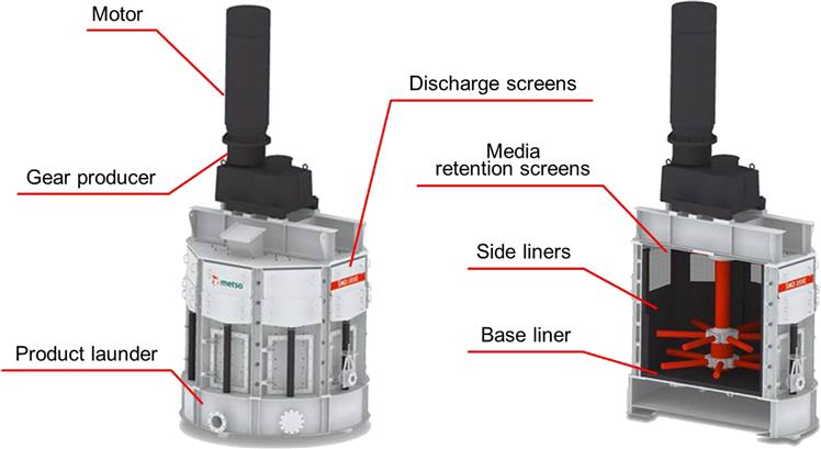
Figure 7.30 shows an SMD®. Normally, natural silica or ceramic is used as the grinding media. Grinding media are added through a pneumatic feed port or the manual feed chute located on top of the mill. Feed slurry enters through a port in the top of the unit.
IsaMill®
Developed by Mount Isa Mines Ltd. (now Glencore Technology) and Netszch-Feinmahltechnik GmbH in the 1990s, the IsaMill® is a large version of the Netszch horizontal stirred mill that was being used for ultrafine grinding applications in various chemical industries. To make this horizontal mill suitable for the mining industry, the engineering challenge was to expand the volume by a factor of 6.
Inside the horizontal shell is a series of rotating discs mounted on a shaft that is coupled to a motor and gearbox (Figure 7.31). The high-speed discs fluidize the media and the slurry that is continuously fed into the feed port. A patented product separator keeps the media inside the mill, allowing only the product to exit. The grinding media can include granulated slag, river sand, ceramic beads or a sized portion of the ore itself.

VXPMill®
Originally developed in the mid-1990s for the fine pigment industry by Deswik Ltd., in 2010 Deswik and Knelson signed a partnership and the name was changed to the Knelson-Deswik mill. In 2012, Knelson became a part of the FLSmidth group and the mill received its present name: the FLSmidth VXPmill®.
HIGMill®
In 2012, Outotec launched a new fine grinding technology for the mineral processing industry. The technology has been utilized for more than 30 years in the calcium carbonate industry, but until recently, was not available for mineral processing.
7.3.4 Some Operational Points
Media
Proper media selection is key for a successful stirred milling application. A balance needs to be achieved between milling efficiency (kWh per ton fresh feed) versus operating costs (cost of media replacement per ton of fresh feed). Milling efficiencies vary with media size, density, and shape.
Media size selection is dependent normally on the feed top size. The design tries to ensure that the top feed size to the mill is controlled and that the medium is a size no larger than needed to handle this feed. In applications where large variations in the feed top size are expected, energy efficiency will need to be sacrificed in order to select a larger media size.
Media density and shape have varying degrees of effect on grinding (Nesset et al., 2006). Typically, spherical media are considered to be energy efficient, although there is evidence that rod shaped media can be more efficient in ultrafine grinding applications (Tamblyn, 2009). For vertical mills, low media density is preferred as dense media sink and results in grinding inefficiency. In horizontal mills, high density media were found to be more efficient (Xu and Mao, 2011).
Media Loading
The energy drawn by a mill is directly related to the media loading. It is recommended to keep a mill fully loaded during operation. Many mills have automated the addition of media so that when mill power draw drops below a set value, a charge of media is added. It is generally easier to control a mill if media loading is constant leaving control dependent on percent solids and slurry flow rate.
Slurry Percent Solids
Optimization of slurry density can result in gains in energy efficiency. If there is too high a water content, the number of contact events between particles and media drops, resulting in less grinding; if the solids content becomes too great, then fluidization of the mill is lost and the only media movement is that directly caused by the impeller.
7.4 Other Grinding Mill Types
Vibratory Mills
These are available for continuous or batch grinding materials to a very fine end product. Two vibrating cylinders charged with ball or rod media are placed either directly above the other or inclined at 30° to perpendicular. Located between the two cylinders is an eccentrically supported weight driven to produce a small circular oscillation of a few millimeters, which fluidizes the mill contents and provides impulses to the material that is ground by attrition. The material, wet or dry, is fed and discharged through flexible bellow-type hoses. Vibratory mills have a small size and low specific energy consumption compared to competing mill types. Three-tube vibratory mill configurations are also available.
Centrifugal Mills
The concept of centrifugal grinding is an old one, and although an 1896 patent describes the process, it has so far not gained full-scale industrial application. The Chamber of Mines of South Africa studied centrifugal milling (Kitschen et al., 1982; Lloyd et al., 1982). Operation of a prototype 1 m diameter, 1 m long, 1 MW mill over an extended period at Western Deep Levels gold mine proved it to be the equivalent of a conventional 4 m×6 m ball mill.
Roller Mills
These mills are often used for the dry grinding of medium soft materials of up to 4–5 mohs hardness. Above this hardness, excessive wear offsets the advantage of lower energy consumption compared with conventional mills.
Table and Roller Mills
These units are used for dry grinding of medium-hard materials such as coal, limestone, phosphate rock, and gypsum. Two or three rollers, operating against coiled springs, grind material which is fed onto the center of a rotating grinding table (Figure 7.32). Ground material spilling over the edge of the table is air-swept into a classifier mounted on the mill casing, coarse particles being returned for further grinding.

Pendulum Roller Mills
Used for dry fine grinding non-metallic minerals such as barytes and limestone, material is reduced by the centrifugal action of suspended rollers running against a stationary grinding ring (Figure 7.33). The rollers are pivoted on a spider support fitted to a gear-driven shaft. Feed material falls onto the mill floor, to be scooped up by ploughs into the “angle of nip” between the rolls and the grinding ring. Ground material is air-swept from the mill into a classifier, oversize material being returned.
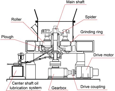
7.5 Grinding Circuits
7.5.1 Circuit Types
The feed can be wet or dry, depending on the subsequent process and the nature of the product. Dry grinding is necessary with some materials due to physical or chemical changes that occur if water is added. Areas with a shortage of water and the growing determination to limit water use may see increased dry grinding in the future. It can cause less wear on the liners and grinding media as there is no corrosion. There also tends to be a higher proportion of fines in the product, which may be desirable in some cases. Control of dust is an issue.
Wet grinding is generally used in mineral processing operations because of the overall economies of operation. The advantages of wet grinding include:
1. Lower power per ton of product.
2. Higher capacity per unit mill volume.
3. Makes possible the use of wet screening or classification for close product control.
4. Eliminates the dust problem.
5. Makes possible the use of simple handling and transport methods such as pumps, pipes, and launders.
The type of mill for a particular grind, and the circuit in which it is to be used, must be considered simultaneously. Circuits are divided into two broad categories, open and closed (the same terms introduced for crushing circuits, Chapters 6 and 8). Figure 7.34 shows the older style rod/ball mill arrangement, which illustrates open circuit, the rod mill, and closed circuit, the ball mill closed with a hydrocyclone (Chapter 9). Figure 7.35 shows a SAG/ball mill circuit where both grinding mills are in closed circuit, the SAG mill closed with a crusher to control the amount of “critical size” material in the circuit (see Chapters 5 and 6). In open circuit, the material is fed to the mill at a rate calculated to produce the correct product in one pass. Open circuit is sometimes used for regrinding iron concentrates for pelletization.


The first mill in the two circuits (Figures 7.34 and 7.35) is sometimes referred to as the “primary” mill, and the second mill as the “secondary”. As well, the circuits may be referred to as “primary circuits” to distinguish them from regrind circuits that may exist downstream in the plant.
The circuit in Figure 7.35 is termed SABC, for Semi-Autogenous, Ball mill, Crusher. In this case the product is recycled to the SAG mill, so this circuit becomes SABC-A to distinguish from another possibility that the crushed product goes to the ball mill, making that a SABC-B circuit. The circuit in Figure 7.35 can be modified by including a separation (flotation) stage between the SAG mill and ball mill, referred to as “stage flotation” (Finch et al., 2007).
Final stages of grinding in the mining industry are almost always in closed circuit, in which material of the required size is removed by a classifier, which returns oversize to the mill, which is commonly a ball mill. Figure 7.36 shows the two closed ball mill-cyclone circuit arrangements: forward classification (a) where the fresh feed goes directly to the mill, and reverse classification (b) where the fresh feed goes first to the classifier. As a rule of thumb, forward circuit classification is used if the fresh feed contains less than 30% finished product (i.e., finer than the circuit product P80). The material returned to the mill by the classifier is known as the circulating load and is expressed as a ratio or percentage of the weight of new feed. (This same term was introduced in Chapter 6 describing the closed crusher/screen arrangement.) Circulating loads are typically 150–350%. The sizing of a ball mill is based on a mill in closed circuit with a 250% circulating load (see Example 7.2).

In closed-circuit operation, no effort is made to effect all the size reduction in a single pass. Instead, every effort is made to remove material from the circuit as soon as it reaches the required size. This has the effect of giving a narrower size distribution in the circuit product (classifier fine product) compared to open circuit, as finished product (fines) is removed quickly and avoids “over-grinding” while the coarse material is preferentially recycled and ground. The larger the circulating load the shorter the residence time in the mill and thus the greater is the content of coarse material in the mill feed. This means that a larger fraction of the grinding energy is being usefully applied to over-size material, which increases the capacity of the circuit to produce a target P80. (See also Chapter 5 discussion on “functional performance analysis”.) This impact on product particle size distribution (PSD) and circuit capacity is illustrated in Figure 7.37. Here the increased fineness and narrowing of the PSD of the closed circuit product compared to the open circuit product at the same tonnage T1 is depicted. The finer product P80 of the closed circuit at T1 (P80CT1) compared to the open case (P80OT1) means the tonnage can be increased (T2>T1) to return to the original open circuit P80 (P80OT1). In this manner, at a given P80 the closed circuit has higher throughput than the open circuit at the same mill power draw.

Another advantage of the closed circuit is that the mill contents become narrower in size distribution as circulating load increases and the distribution changes less from feed to discharge, making it, in principle, easier to optimize the media size to particle size, which further increases grinding energy efficiency.
The optimum circulating load for a particular circuit depends on the classifier capacity and the cost of transporting (pumping) the load to the mill. It is usually in the range of 100–350%, although it can be as high as 600%. The increase in capacity is most rapid in the first 100% of circulating load, then continues up to a limit, depending on the circuit, just before the mill “chokes” (i.e., is overloaded, identified in an overflow mill by balls sometimes exiting with the slurry). The increase in capacity can be considerable: Davis, as quoted by Gaudin (1939), showed the quantity of new −150 mesh (−105 µm) material increased by about 2.5 times as the circulating load increased from zero (i.e., open circuit) to 250%. While some current work is challenging this finding (Jankovic and Valery, 2013), it is still widely used as a guide to increasing ball mill-cyclone circuit efficiency (McIvor, 2014).
Similar considerations apply to regrind applications. Using a ball mill, it is usually closed with a cyclone. With the newer stirred mills there may be a combination of internal and external classification. Given the increasing fine size demanded and achievable with stirred mills, efficient classification becomes a challenge.
Various types of classifying devices can be used to close the circuit (Chapter 9). Mechanical classifiers are still found in some older mills, but suffer from classifying by gravitational force, which restricts their capacity when dealing with fine material. Hydrocyclones (or simply “cyclones”) classify by centrifugal action, which intensifies the classification of fine particles, giving sharper separations and allowing higher circulating loads. They occupy much less floor space than mechanical classifiers of the same capacity and have lower capital and installation costs. Due to their fast response, the grinding circuit can rapidly be brought into balance if changes are made and the reduced dwell time of particles in the circuit gives less time for oxidation to occur, which may be important with sulfide minerals that are to be subsequently floated. Cyclones have, therefore, come to dominate grinding circuits preceding flotation operations. Figure 7.38 shows a ball mill/cyclone closed circuit installation.

The action of all classifiers in grinding circuits is dependent on the differential settling rates of particles in a fluid, which means that particles are classified not only by size but also by specific gravity. Consequently, a small dense particle may classify in a similar way to a large, low-density particle. Thus, when an ore containing a heavy valuable mineral is fed to a closed grinding circuit, this mineral is preferentially recycled compared to the low density mineral (usually gangue) and is ground finer. (This effect of density on classification is discussed further in Chapter 9.) Selective grinding of heavy sulfides in this manner prior to flotation can allow a coarser overall grind, the light, coarse gangue reporting to the classifier overflow, while the heavy valuable mineral particles are selectively ground. It can, however, pose problems with gravity and magnetic separation circuits, where particles should be as coarse and as closely sized as possible in order to achieve maximum separation efficiency.
To address the differential mineral classification due to density has contributed to the use of “double classification” (Castro et al., 2009), which re-classifies the cyclone underflow, and stimulated development of the “three-product cyclone” (Obeng and Morrell, 2003). In some cases circuits can be closed by screens rather than classifiers, which cut on the basis of size only, as discussed in Chapter 8. Combinations of classifiers and screens are another option.
Other strategies aim to take advantage of the concentration of heavy minerals in the circulating load. A flotation unit (“flash flotation”) or gravity separation stage can be incorporated in the grinding circuit, e.g., on the cyclone underflow, cyclone feed or ball mill discharge. Incorporation of gravity separation is almost universal in gold circuits with a high degree of “gravity recoverable gold” (Chapter 10), and in some instances can be extended to the recovery of platinum group minerals.
Multi-stage grinding, in which ball mills are arranged in series, can be used to produce successively finer products (Figure 7.39). These circuits introduce the possibility of separation stages between the grinding units but the trend is toward large single-stage primary ball mills, both to reduce capital and operating costs and to facilitate automatic control. The disadvantage of single-stage milling is that if a high reduction ratio is required, then relatively large balls are required for coarse feed, which may not efficiently grind the finer particles.

Rosario et al. (2009) review trends in comminution circuit design with reference to high tonnage hard rock operations. The circuits described, in addition to the ones introduced above, include: SAG mill closed with a screen (no recycle crusher); use of HPGR (high pressure grinding roll) as the recycle crusher; pre-crushing ahead of a SABC circuit; and HPGR with stirred mills.
7.5.2 Circuit Operation
Grinding circuits are fed at a controlled rate from the stockpile or bins holding the crusher plant product. There may be a number of grinding circuits in parallel, each circuit taking a definite fraction of the feed. An example is the Highland Valley Cu/Mo plant with five parallel grinding lines (Chapter 12). Parallel mill circuits increase circuit flexibility, since individual units can be shut down or the feed rate can be changed, with a manageable effect on production. Fewer mills are, however, easier to control and capital and installation costs are lower, so the number of mills must be decided at the design stage.
The high unit capacity SAG mill/ball mill circuit is dominant today and has contributed toward substantial savings in capital and operating costs, which has in turn made many low-grade, high-tonnage operations such as copper and gold ores feasible. Future circuits may see increasing use of high pressure grinding rolls (Rosas et al., 2012).
Autogenous grinding or semi-autogenous grinding mills can be operated in open or closed circuit. However, even in open circuit, a coarse classifier such as a trommel attached to the mill, or a vibrating screen can be used. The oversize material is recycled either externally or internally. In internal recycling, the coarse material is conveyed by a reverse spiral or water jet back down the center of the trommel into the mill. External recycling can be continuous, achieved by conveyor belt, or is batch where the material is stockpiled and periodically fed back into the mill by front-end loader.
In Figure 7.35 shows the SAG mill closed with a crusher (recycle or pebble crusher). In SAG mill operation, the grinding rate passes through a minimum at a “critical size” (Chapter 5), which represents material too large to be broken by the steel grinding media, but has a low self-breakage rate. If the critical size material, typically 25–50 mm, is accumulated the mill energy efficiency will deteriorate, and the mill feed rate decreases. As a solution, additional large holes, or pebble ports (e.g., 40–100 mm), are cut into the mill grate, allowing coarse material to exit the mill. The crusher in closed circuit is then used to reduce the size of the critical size material and return it to the mill. As the pebble ports also allow steel balls to exit, a steel removal system (such as a guard magnet, Chapters 2 and 13) must be installed to prevent them from entering the crusher. (Because of this requirement, closing a SAG mill with a crusher is not used in magnetic iron ore grinding circuits.) This circuit configuration is common as it usually produces a significant increase in throughput and energy efficiency due to the removal of the critical size material.
An example SABC-A circuit is the Cadia Hill Gold Mine, New South Wales, Australia (Dunne et al., 2001). The project economics study indicated a single grinding line. The circuit comprises a SAG mill, 12 m diameter by 6.1 m length (belly inside liners, the effective grinding volume), two pebble crushers, and two ball mills in parallel closed with cyclones. The SAG mill is fitted with a 20 MW gearless drive motor with bi-directional rotational capacity. (Reversing direction evens out wear on liners with symmetrical profile and prolongs operating time.) The SAG mill was designed to treat 2,065 t h−1 of ore at a ball charge of 8% volume, total filling of 25% volume, and an operating mill speed of 74% of critical. The mill is fitted with 80 mm grates with total grate open area of 7.66 m2 (Hart et al., 2001). A 4.5 m diameter by 5.2 m long trommel screens the discharge product at a cut size of ca. 12 mm. Material less than 12 mm falls into a cyclone feed sump, where it is combined with discharge from the ball mills. Oversize pebbles from the trommel are conveyed to a surge bin of 735 t capacity, adjacent to the pebble crushers. Two cone crushers with a closed side set of 12–16 mm are used to crush the pebbles with a designed product P80 of 12 mm and an expected total recycle pebble rate of 725 t h−1. The crushed pebbles fall directly onto the SAG mill feed belt and return to the SAG mill.
SAG mill product feeds two parallel ball mills of 6.6 m×11.1 m (internal diameter×length), each with a 9.7 MW twin pinion drive. The ball mills are operated at a ball charge volume of 30–32% and 78.5% critical speed. The SAG mill trommel undersize is combined with the ball mills’ discharge and pumped to two parallel packs (clusters) of twelve 660 mm diameter cyclones. The cyclone underflow from each line reports to a ball mill, while the cyclone overflow is directed to the flotation circuit. The designed ball milling circuit product is 80% passing 150 µm.
Several large tonnage copper porphyry plants in Chile use an open-circuit SAG configuration where the pebble crusher product is directed to the ball mills (SABC-B circuit). The original grinding circuit at Los Bronces is an example: the pebbles generated in the two SAG mills are crushed in a satellite pebble crushing plant, and then are conveyed to the three ball mills (Moglía and Grunwald, 2008).
7.5.3 Control of the Grinding Circuit
The purpose of milling is to reduce the size of the ore particles to the point where economic liberation of the valuable minerals takes place. Thus, it is essential that not only should a milling circuit process a certain tonnage of ore per day, but should also yield a product that is of known and controllable particle size. The principal variables that can affect control are: changes in the feed rate and the circulating load, size distribution and hardness of the ore, and the rate of water addition to the milling circuit. Operational factors are also important, such as to add grinding media into the mill or clear a plugged cyclone. For the purposes of stabilizing control, feed rate, densities, and circulating loads may be maintained at optimal values that would produce the required product (typically known through experience); however, this objective fails when disturbances cause deviations from target values. Fluctuation in feed size and hardness are probably the most significant factors disturbing the balance of a grinding circuit. Such fluctuations may arise from differences in composition, mineralization, particle size of the feed, and texture of the ore from different parts of the mine, from changes in mining methods (e.g., blast pattern), from changes in the crusher settings, often due to wear, and from damage to screens in the crushing circuit. Minor fluctuations in ore characteristics can be smoothed out by ore blending prior to feeding to the crusher. Ore storage increases smoothing out of variations, provided that ore segregation does not take place in the coarse-ore stockpile or storage bins. The amount of storage capacity available depends on the nature of the ore (such as its tendency to oxidize) and on the mill economics (real estate, capital budget, etc.).
Increase in feed size or hardness produces a coarser mill product unless the feed rate is proportionally reduced. Conversely, a decrease in feed size or hardness may allow an increase in mill throughput. A coarser mill product results in a greater circulating load from the classifier, thus increasing the volumetric flow rate. Since the product size from a hydrocyclone (type of classifier) is affected by flow rate (Chapter 9), the size distribution of the product will change. Control of the circulating load is therefore crucial in control of product particle size. A high circulating load at a fixed product size means lower energy consumption, but excessive circulating loads may result in the mill, classifier, conveyor, or pump overloading, hence there is an upper limit to mill feed rate. Determination of circulating load from a sampling campaign was illustrated in Chapter 3, Example 3.15.
Grinding is the most energy intensive section in a mineral processing plant, and the product from grinding has a major impact on subsequent separation processes, hence close control is required. Automatic control of milling circuits is one of the most advanced and successful areas of the application of process control in the minerals industry (Herbst et al., 1988). Control of grinding circuits is reviewed by Wei and Craig (2009) and Flintoff et al. (2014).
Instrumentation
Typical instrumentation is illustrated in Figure 7.40 for a primary (AG/SAG or rod) mill-secondary ball mill/cyclone circuit. Control of the feed rate is essential, and devices such as variable speed apron feeders or feeder belts, in conjunction with weightometers, are often used. Slurry density is measured mainly by nuclear density gauges, and flow rates by magnetic flowmeters or, increasingly, CiDRA’s SONARtrac® technology (Chapter 3). Sump level is commonly indicated by bubble tube, capacitance-type detectors, or other electronic devices.

Newer mills are often equipped with variable speed drives, allowing mill rotational speed to be adjusted as an additional (and important) degree of freedom. Control of the grinding media charge can be made by continuous monitoring of the mill power consumption. A fall in power consumption to a certain level necessitates charging of fresh grinding media. Continuous power monitoring finds its greatest use in autogenous grinding, the power drawn being used as a measure of mill load and a constraint on mill feed rate. AG/SAG mills with crushers in pebble recirculation loops can utilize the crusher operating time or closed side setting (Chapter 6) to control the size of crushed pebbles returning to the mill, which in turn affects mill load and circulating load.
Arguably, the most important parameter required to provide good control of mill performance (especially AG/SAG mills) is the load (or amount of charge) inside the mill. Volumetric load (the percentage of mill internal volume taken up by ore and grinding media) is the key variable as it affects how the charge behaves inside the mill (e.g., shoulder and toe positions, Figure 7.3), but cannot currently be measured online, so it must be inferred from other, measurable parameters. Two categories of instruments are available: “off-shell” stationary sensors and “on-shell” sensors attached to the shell (Tano, 2005). On-shell load monitoring is an advancing field and includes a variety of measurement techniques. The strain experienced by the mill shell or lifter bars/bolts can be measured to determine when the lifter is within the charge volume and thus the position of the toe and shoulder of the charge (Herbst and Gabardi, 1988; Kolacz, 1997; Tano, 2005). Conductivity inside the mill, as measured by two probes mounted on a lifter, can provide a similar measurement of the shape and position of the charge (Moys, 1988; Vermeulen and Schakowski, 1988). The mechanical vibrations caused by grinding can be detected by accelerometers attached to the mill shell or bearings and analyzed to determine charge motion and detect various operational conditions (Campbell et al., 2001, 2006).
Acoustic systems use a single sensor or an array of microphones to detect the sound vibrations produced by charge movement inside the mill and can be mounted close to the mill or on the shell itself. These have been increasingly included in mill control systems in recent years. They can have considerable advantages over load cells (Pax, 2001) due to their ease of maintenance and the additional process information they provide. One system is to use two off-shell microphones, one placed above, and the other placed below the normal level of impact of the charge on the mill shell. As the mill load increases, the point of impact moves toward the upper microphone, and conversely down toward the lower microphone as it decreases. By comparing the output from the two microphones, it becomes possible to determine whether the charge level is rising or falling. This information is correlated with the power draw of the mill and used to calculate the rate of addition of the new feed. It was found that the sound level changed ahead of detectable changes in the mill bearing pressure, power, torque, motor current, and mill weight. Therefore the plant took the sound reading as an indicator of changes in SAG load for milling circuit control. Other systems adjust mill speed in response to acoustic information to control the mill load and ensure maximum grinding efficiency by moving the point of impact to the toe of the charge (Pax et al., 2014). Several commercial systems are available to analyze the sound produced by the mill and detect factors such as ball-on-liner impacts, charge geometry (toe and shoulder position), water holdup or specific information on the behavior of balls and ore, and is used to infer the mill volumetric loading (La Rosa et al., 2008; Pax, 2011, 2012; Pax et al., 2014; Shuen et al., 2014). Sound-based systems tend to be more successful in the long term as a tool to detect steel-on-liner collisions and therefore indicate when the mill should be slowed to protect the liners rather than a real time indicator of load. This is primarily due to calibration drift and the influence of unmeasured acoustic disturbances in the concentrator.
Measurement of mill weight has mainly been by load cells, which directly measure the mass of material in the mill (including ore, grinding media, water, shell, and liners), from which the volumetric load can be inferred. These instruments, however, rely on accurate calibration, do not take into account changes in rod/ball charge or liner wear, require downtime for maintenance and are prone to drift, so alternative measurements are often used. The most common approach is inferring mill weight by monitoring the pressure of lubricating oil flowing through the mill bearings. However, this measure can be susceptible to signal noise and is impacted by the physical properties of the oil (temperature, viscosity) and system hydraulics. Bearing pressure is nonetheless utilized in many AG/SAG mills as an indicator of the load in the mill and is incorporated into control systems. Other systems use the power draw (more specifically the amplitude and frequency of power oscillations) to calculate the position of the charge and determine mill load (Koivistoinen and Miettunen, 1989).
Particle size is obviously a desirable measurement in a grinding circuit. The particle size of the circuit product (cyclone overflow) can be inferred by the use of mathematical models (Chapter 9) but it is preferable to measure directly by the use of on-line monitors, which recent developments are making increasingly robust (Chapter 4). As noted by Flintoff et al. (2014), on-line measurement of liberation would be a notable breakthrough for grinding circuit control.
Mill feed particle size is significant for AG/SAG load management. Monitoring of the feed to the mill by image analysis, for example, provides a measure of the particle size distribution (Chapter 4). Felsher et al. (2015) describe stabilization of SAG power draw by adjusting apron feeder ratios to target higher fines fraction in the SAG feed.
Upset conditions in cyclone operations, such as roping and plugging, have a significant impact on the plant stability and performance, but they often go undetected for extended periods of time due to lack of instrumentation. There are technologies and sensing methods today for monitoring cyclone performance (Chapter 4). When integrated with the plant control system, “offending” cyclones can be automatically switched off so that corrective action is taken within seconds rather than many minutes.
Pumpbox control plays a significant role in stability of the circuit. Many mineral processing plants run their cyclone feed pumpboxes using traditional level control, where the pump speed adjusts to maintain a constant level in the pumpbox. The issue with this philosophy is that a continuously varying flowrate to the cyclopac leads to variability in cyclone pressure and cut-point, which negatively impacts recovery in downstream operations. Pumpbox level management strategy, focused around stabilizing the flowrate to the cyclones, is designed to allow the level in the cyclone feed pumpbox to vary while maintaining the pump speed (Westendorf et al., 2015). The result is more consistent grind size to downstream operations as well as stabilized circulating load within the grinding circuit. Reductions of variability in excess of 50% have been reported.
Control Objectives/strategies
In implementing instrumentation and process control for grinding circuits, the control objective must first be defined, which may be to:
1. Maintain a constant feed rate within a limited range of product size.
2. Maintain a constant product size at maximum throughput.
3. Maximize production per unit time in conjunction with downstream circuit performance (e.g., flotation recovery).
Aspects of grinding circuit control can be introduced using Figure 7.40. Of the variables shown, only the ore feed and the water addition rates can be varied independently, as the other variables depend upon and respond to changes in these items. It is therefore ore feed rate and water addition to the mill and classifier that are the major manipulated variables used to control grinding circuits. There is an important difference in the dynamic response of the circuit to changes in ore feed rate and to changes in water addition rate. Changes in ore feed rate initiate a slow progressive change to the final steady state condition, while changes in classifier water addition initiate an immediate response. Increase in water addition rate also results in a simultaneous increase in circulating load and sump level, confirming the necessity of using a large capacity sump and variable speed pump to maintain effective control.
If the strategy is constant product size at constant feed rate (objective 1), then the only manipulated variable is the classifier water, and the circuit must therefore tolerate variations in the cyclone overflow density and volumetric flow rate when ore characteristics change. Such variations have to be considered with respect to downstream operations (objective 3). Variations in circulating load will also occur. Changes in mill rotational speed provide a fast response in the circuit because the mill discharge rate will be rapidly affected; however, this can lead to instability in the circulating load, hence speed control loops are generally tuned to be slow-acting to ensure stability. Additionally, mill speed has a direct relationship to power draw, meaning that in an overload or high-power situation, increasing the speed of the mill will cause a further increase in power before the mill will begin to unload.
In many applications, the control objective is maximum throughput at constant particle size (objective 2), which allows manipulation of both ore feed rate and classifier water addition rate. Allowing for the fact that the circuit has a limited capacity, this objective can be stated as a fixed product particle size set-point at a circulating load set-point corresponding to a value just below the maximum tonnage constraint. The circulating load is either calculated from measured values, measured directly, or inferred.
Since both ore feed rate and classifier water addition rate can be varied independently, two control strategies are available for objective 2. In the first, product size is controlled by ore feed rate and the circulating load by classifier water addition rate. In the second, product size is controlled by the classifier water addition rate and circulating load by the ore feed rate. The choice of control strategy depends on which of the control loops, the particle size loop or the circulating load loop, is required to respond faster. This depends on many factors, such as the ability of the grinding and concentration circuits to handle variations in flow, the sensitivity of the concentration process to deviations from the optimum particle size, time lags within the grinding circuit, and the number of grinding stages. If the particle size response must be fast, then this loop is controlled by the classifier water, whereas if a fast mill throughput response is more important, then the product size is controlled by the ore feed rate.
It is important to consider the impact of unmeasured disturbances within the grinding circuit, such as ore hardness, liner, lifter, and grate condition, media charge and holdup in the mill. The importance of these parameters makes traditional control difficult, resulting in the need for more advanced techniques.
A common problem in the operation of a milling circuit, particularly when controlling particle size, is that the control actions are often constrained by physical or operational limitations. This problem is particularly relevant in the case of multivariable control, in which control of the process depends critically on the correct combination of several control actions. The saturation of one of these control actions may result in partial loss of control, or even instability of the process. In order to deal with this problem, a method has been developed, in which the multivariable control scheme includes a robust “limit algorithm”, thus retaining effective stabilizing control of the milling process (Hulbert et al., 1990; Craig et al., 1992; Metzner, 1993; Galán et al., 2002). Alternatively, an expert system is incorporated to “manage” the controllers and modify the action based on the situation in the plant.
Expert systems are an accepted form of control for complex grinding circuits. Expert systems are computer programs that compile the process knowledge and rules employed by the control room operators into a heuristic model (Chapter 3). They allow continuous monitoring of the grinding circuit, applying operational best practice consistently. They require little additional investment and infrastructure and can operate from a desktop computer. Several commercial systems are in use.
Model-predictive control has its origins in work done in the 1970s (Lynch, 1977) and gained ground with the advent of more reliable models and more powerful computing platforms (Herbst et al., 1993; Evans, 2001; Galán et al., 2002; Lestage et al., 2002; Muller et al., 2003; Schroder et al., 2003; Yutronic and Toro, 2010). This approach involves development of mathematical models of a unit or a circuit based on existing knowledge, operating mechanisms, and experimental data. Such models often incorporate a number of model parameters that need to be calibrated by experimental data from a specific unit or circuit. Once the model parameters are determined and the ore breakage characteristics are known, the models can predict the performance of the unit or the circuit in response to changes in the feed condition or the operational conditions, either steady-state performance or the dynamic response. The model can also be used in conjunction with an expert system (Felsher et al., 2015) whereby the model predictive controller provides a fundamental foundation for stabilization and the expert system uses heuristics for optimization, providing a framework for the controllers to work within.