Chapter 12
Group Technology
12.1 Introduction
Group technology (abbreviated GT) is a manufacturing philosophy in which similar parts are identified and grouped together to take advantage of their similarities in manufacturing and design. Similar parts are arranged into part families. For example, a plant producing 10,000 different part numbers may be able to group the vast majority of these parts into 50 or 60 distinct families. Each family would possess similar design and manufacturing characteristics. Hence, the processing of each member of a given family would be similar, and this results in manufacturing efficiencies. These efficiencies are achieved in the form of reduced setup times, lower in-process inventories, better scheduling, improved tool control, and the use of standardized process plans. In some plants where GT has been implemented, the production equipment is arranged into machine groups, or cells, in order to facilitate work flow and parts handling.
In product design, there are also advantages obtained by grouping parts into families. For example, a design engineer faced with the task of developing a new part design must either start from scratch or pull an existing drawing from the files and make the necessary changes to conform to the requirements of the new part.
The problem is that finding a similar design may be quite difficult and time consuming. For a large engineering department, there may be thousands of drawings in the files with no systematic way to locate the desired drawing. As a consequence, the designer may decide that it is easier to start from scratch in developing the new part. This decision is replicated many times over in the company, thus consuming valuable time creating duplicate or near-duplicate part designs. If an effective design-retrieval system were available, this waste could be avoided by permitting the engineer to determine quickly if a similar part already exists. A simple change in an existing design would be much less time consuming than starting from scratch. This design-retrieval system is a manifestation of the group technology principle applied to the design function. To implement such a system, some form of parts classification and coding is required.
Parts classification and coding is concerned with identifying the similarities among parts and relating these similarities to a coding system. Part similarities are of two types: design attributes (such as geometric shape and size), and manufacturing attributes (the sequence of processing steps required to make the part). While the processing steps required to manufacture a part are usually correlated with the part’s design attributes, this is not always the case. Accordingly, classification and coding systems are often devised to allow for differences between a part’s design and its manufacture.
Whereas a parts classification and coding system is required in a design-retrieval system, it can also be used in computer-aided process planning (CAPP). Computer-aided process planning involves the automatic generation of a process plan (or route sheet) to manufacture the part. The process routing is developed by recognizing the specific attributes of the part in question and relating these attributes to the corresponding manufacturing operations.
In the present chapter we develop the topics of group technology and parts classification and coding. In the following chapter we present a discussion of computer-aided process planning and several related issues. Group technology and parts classification and coding are based on the concept of a part family.
12.2 Part Families
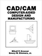
A part family is a collection of parts which are similar either because of geometric shape and size or because similar processing steps are required in their manufacture. The parts within a family are different, but their similarities are close enough to merit their identification as members of the part family. Figures 12.1 and 12.2 show two part families. The two parts shown in Figure 12.1 are similar from a design viewpoint but quite different in terms of manufacturing. The parts shown in Figure 12.2 might constitute a part family in manufacturing, but their geometry characteristics do not permit them to be grouped as a design part family.
The part family concept is central to design-retrieval systems and most current computer-aided process planning schemes. Another important manufacturing
Figure 12.1 Two parts of identical shape and size but different manufacturing requirements.
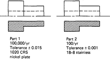
Figure 12.2 Thirteen parts with similar manufacturing process requirements but different design attributes.

advantage derived from grouping workparts into families can be explained with reference to Figures 12.3 and 12.4. Figure 12.3 shows a process-type layout for batch production in a machine shop. The various machine tools are arranged by function. There is a lathe section, milling machine section, drill press section, and so on. During the machining of a given part, the workpiece must be moved between sections, with perhaps the same section being visited several times. This results in a significant amount of material handling, a large in-process inventory, usually more setups than necessary, long manufacturing lead times, and high cost. Figure 12.4 shows a production shop of supposedly equivalent capacity, but with the machines arranged into cells. Each cell is organized to specialize in the manufacture of a particular part family. Advantages are gained in the form of
Figure 12.3 Process-type layout.

Figure 12.4 Group technology layout.

reduced workpiece handling, lower setup times, less in-process inventory, less floor space, and shorter lead times. Some of the manufacturing cells can be designed to form production flow lines, with conveyors used to transport workparts between machines in the cell.
The biggest single obstacle in changing over to group technology from a traditional production shop is the problem of grouping parts into families. There are three general methods for solving this problem. All three methods are time consuming and involve the analysis of much data by properly trained personnel. The three methods are:
2. Production flow analysis (PFA)
3. Parts classification and coding system
The visual inspection method is the least sophisticated and least expensive method. It involves the classification of parts into families by looking at either the physical parts or photographs and arranging them into similar groupings. This method is generally considered to be the least accurate of the three.
The second method, production flow analysis, was developed by J. L. Bur-bidge [3,6]. PFA is a method of identifying part families and associated machine tool groupings by analyzing the route sheets for parts produced in a given shop. It groups together the parts that have similar operation sequences and machine routings. The disadvantage of PFA is that it accepts the validity of existing route sheets, with no consideration given to whether these process plans are logical or consistent. The production flow analysis approach does not seem to be used much at all in the United States.
The third method, parts classification and coding, is the most time consuming and complicated of the three methods. However, it is the most frequently applied method and is generally recognized to be the most powerful of the three.
12.3 Parts Classification and Coding
This method of grouping parts into families involves an examination of the individual design and/or manufacturing attributes of each part. The attributes of the part are uniquely identified by means of a code number. This classification and coding may be carried out on the entire list of active parts of the firm, or a sampling process may be used to establish the part families. For example, parts produced in the shop during a certain given time period could be examined to identify part family categories. The trouble with any sampling procedure is the risk that the sample may be unrepresentative of the entire population. However, this risk may be worth taking, when compared to the relatively enormous task of coding all the company’s parts.
Many parts classification and coding systems have been developed throughout the world, and there are several commercially available packages being sold to industrial concerns. It should be noted that none of them has been universally adopted. One of the reasons for this is that a classification and coding system should be custom-engineered for a given company or industry. One system may be best for one company while a different system is more suited to another company. In Section 12.4 we review several of the most familiar parts classification and coding systems. It is the purpose of this section to explain the general structure of these systems.
Table 12.1 Design and Manufacturing Part Attributes Typically Included in a Group Technology Classification System
Design systems versus manufacturing systems
Parts classification and coding systems divide themselves into one of three general categories:
1. Systems based on part design attributes
2. Systems based on part manufacturing attributes
3. Systems based on both design and manufacturing attributes
Systems in the first category are useful for design retrieval and to promote design standardization. Systems in the second category are used for computer-aided process planning, tool design, and other production-related functions. The third category represents an attempt to combine the functions and advantages of the other two systems into a single classification scheme. The types of design and manufacturing parts attributes typically included in classification schemes are listed in Table 12.1. It is clear that there is a certain amount of overlap between the design and manufacturing attributes of a part.
Coding system structure
A parts coding scheme consists of a sequence of symbols that identify the part’s design and/or manufacturing attributes. The symbols in the code can be all numeric, all alphabetic, or a combination of both types. However, most of the common classification and coding systems use number digits only. There are three basic code structures used in group technology applications:
2. Chain-type structure
3. Hybrid structure, a combination of hierarchical and chain-type structures
With the hierarchical structure, the interpretation of each succeeding symbol depends on the value of the preceding symbols. Other names commonly used for this structure are monocode and tree structure. The hierarchical code provides a relatively compact structure which conveys much information about the part in a limited number of digits.
In the chain-type structure, the interpretation of each symbol in the sequence is fixed and does not depend on the value of preceding digits. Another name commonly given to this structure is polycode. The problem associated with polycodes is that they tend to be relatively long. On the other hand, the use of a polycode allows for convenient identification of specific part attributes. This can be helpful in recognizing parts with similar processing requirements.
To illustrate the difference between the hierarchical structure and the chain-type structure, consider a two-digit code, such as 15 or 25. Suppose that the first digit stands for the general part shape. The symbol 1 means round workpart and 2 means flat rectangular geometry. In a hierarchical code structure, the interpretation of the second digit would depend on the value of the first digit. If preceded by 1, the 5 might indicate some length/diameter ratio, and if preceded by 2, the 5 might be interpreted to specify some overall length. In the chain-type code structure, the symbol 5 would be interpreted the same way regardless of the value of the first digit. For example, it might indicate overall part length, or whether the part is rotational or rectangular.
Most of the commercial parts coding systems used in industry are a combination of the two pure structures. The hybrid structure is an attempt to achieve the best features of monocodes and polycodes. Hybrid codes are typically constructed as a series of short polycodes. Within each of these shorter chains, the digits are independent, but one or more symbols in the complete code number are used to classify the part population into groups, as in the hierarchical structure. This hybrid coding seems to best serve the needs of both design and production.
12.4 Three Parts Classification and Coding Systems
When implementing a parts classification and coding system, most companies elect to purchase a commercially available package rather than develop their own. Inyong Ham [8] recommends that the following factors be considered in selecting a parts coding and classification system:
Objective. The prospective user should first define the objective for the system. Will it be used for design retrieval or part-family manufacturing or both?
Scope and application. What departments in the company will use the system? What specific requirements do these departments have? What kinds of information must be coded? How wide a range of products must be coded? How complex are the parts, shapes, processes, tooling, and so forth?
Costs and time. The company must consider the costs of installation, training, and maintenance for their parts classification and coding system. Will there be consulting fees, and how much? How much time will be required to install the system and train the staff to operate and maintain it? How long will it be before the benefits of the system are realized?
Adapability to other systems. Can the classification and coding system be readily adapted to the existing company computer systems and data bases? Can it be readily integrated with other existing company procedures, such as process planning, NC programming, and production scheduling?
Management problems. It is important that all involved management personnel be informed and supportive of the system. Also, will there be any problems with the union? Will cooperation and support for the system be obtained from the various departments involved?
In the sections below, we review three parts classification and coding systems which are widely recognized among people familiar with GT:
1. Opitz system
2. MICLASS system
3. CODE system
The Opitz classification system
This parts classification and coding system was developed by H. Opitz of the University of Aachen in West Germany. It represents one of the pioneering efforts in the group technology area and is perhaps the best known of the classification and coding schemes.
The Opitz coding system uses the following digit sequence:
12345 6789 ABCD
The basic code consists of nine digits, which can be extended by adding four more digits. The first nine digits are intended to convey both design and manufacturing data. The general interpretation of the nine digits is indicated in Figure 12.5. The first five digits, 12345, are called the “form code” and describe the primary design attributes of the part. The next four digits, 6789, constitute the “supplementary
Figure 12.5 Basic structure of the Opitz system.

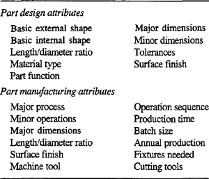
Figure 12.6 Form code (digits 1 through 5) for rotational parts in the Opitz system.
code.” It indicates some of the attributes that would be of use to manufacturing (dimensions, work material, starting raw workpiece shape and accuracy). The extra four digits, ABCD, are referred to as the “secondary code” and are intended to identify the production operation type and sequence. The secondary code can be designed by the firm to serve its own particular needs.
The complete coding system is too complex to provide a comprehensive description here. Opitz wrote an entire book on his system [12]. However, to obtain a general idea of how the Opitz system works, let us examine the first five digits of the code, the form code. The first digit identifies whether the part is a rotational or a nonrotational part. It also describes the general shape and proportions of the part. We will limit our survey to rotational parts possessing no unusual features, those with code values 0, 1, or 2. See Figure 12.5 for definitions. For this general class of workparts, the coding of the first five digits is given in Figure 12.6. An example will demonstrate the coding of a given part.
Example 12.1
Given the part design of Figure 12.7, define the “form code” (the first five digits) using the Opitz system.
The overall length/diameter ratio, L/D = 1.5, so the first digit code = 1. The part is stepped on both ends with a screw thread on one end, so the second digit code would be 5. The third digit code is 1 because of the through-hole. The fourth and fifth digits are both 0, since no surface machining is required and there are no auxiliary holes or gear teeth on the part. The complete form code in the Opitz system is 15100. To add the supplementary code, we would have to properly code the sixth through ninth digits with data on dimensions, material, starting workpiece shape, and accuracy.
The Miclass System
MICLASS stands for Metal Institute Classification System and was developed by TNO, the Netherlands Organization for Applied Scientific Research [18]. It was started in Europe about five years before being introduced in the United States in
Figure 12.7 Workpart for Example 12.1

1974. Today, it is marketed in the United States by the Organization for Industrial Research in Waltham, Massachussets. The MICLASS system was developed to help automate and standardize a number of design, production, and management functions. These include:
Standardization of engineering drawings
Retrieval of drawings according to classification number
Standardization of process routing
Automated process planning
Selection of parts for processing on particular groups of machine tools
Machine tool investment analysis
The MICLASS classification number can range from 12 to 30 digits. The first 12 digits are a universal code that can be applied to any part. Up to 18 additional digits can be used to code data that are specific to the particular company or industry. For example, lot size, piece time, cost data, and operation sequence might be included in the 18 supplementary digits.
The workpart attributes coded in the first 12 digits of the MICLASS number are as follows:
1st digit Main shape
2nd and 3rd digits Shape elements
4th digit Position of shape elements
5th and 6th digits Main dimensions
7th digit Dimension ratio
8th digit Auxiliary dimension
9th and 10th digits Tolerance codes
11th and 12th digits Material codes
One of the unique features of the MICLASS system is that parts can be coded using a computer interactively. To classify a given part design, the user responds to a series of questions asked by the computer. The number of questions depends on the complexity of the part. For a simple part, as few as seven questions are needed to classify the part. For an average part, the number of questions ranges between 10 and 20. On the basis of the responses to its questions, the computer assigns a code number to the part. Because the system developer, TNO, is an international organization, the program was written to converse in any of four languages: English, French, German, or Dutch. Also, it can operate in either inches or metric, or both. An example will illustrate the use of the MICLASS computer system for parts classification.
Example 12.2
Figure 12.8 shows a rotational part to be classified and coded using MICLASS. Dimensions are given in inches. Figure 12.9 shows a copy of the user interrogation by the computer.
Figure 12.8 Workpart for Example 12.2. (Reprinted from Ref. [14].)
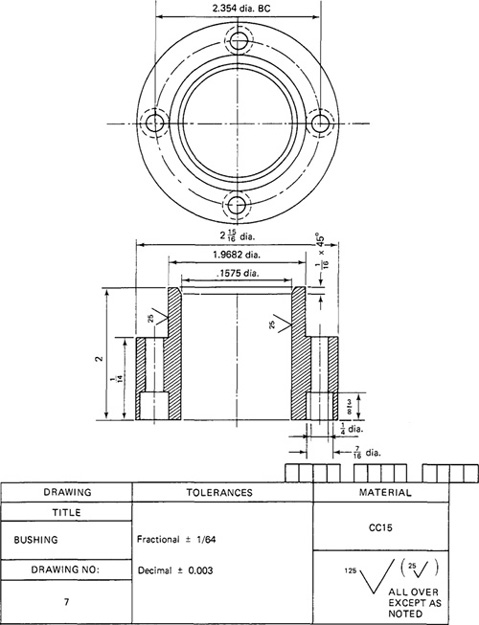
Figure 12.9 Computerized MICLASS system determination of code number for workpart of Example 12.2. (Reprinted from Ref. [14].)
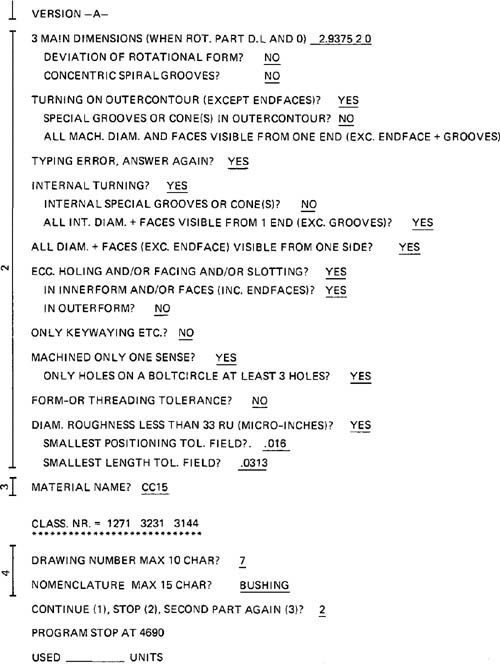
Most of the questions require “Yes” and “No” answers determined from a user analysis of the part drawing. When the interrogation is completed, the computer prints the proper code number. For this part, the universal code (the first 12 digits) is 1271 3231 3144.
The CODE system
The CODE system is a parts classification and coding system developed and marketed by Manufacturing Data Systems, Inc. (MDSI), of Ann Arbor, Michigan. Its most universal application is in design engineering for retrieval of part design data, but it also has applications in manufacturing process planning, purchasing, tool design, and inventory control.
The CODE number has eight digits. For each digit there are 16 possible values (zero through 9 and A through F) which are used to describe the part’s design and manufacturing characteristics. The initial digit position indicates the basic geometry of the part and is called the Major Division of the CODE system. This digit would be used to specify whether the shape was a cylinder, flat piece, block, or other. The interpretation of the remaining seven digits depends on the value of the first digit, but these remaining digits form a chain-type structure. Hence the CODE system possesses a hybrid structure.
The second and third digits provide additional information concerning the basic geometry and principal manufacturing process for the part. Digits 4, 5, and 6 specify secondary manufacturing processes such as threads, grooves, slots, and so forth. Digits 7 and 8 are used to indicate the overall size of the part (e.g., diameter and length for a turned part) by classifying it into one of 16 size ranges for each of two dimensions. Figure 12.10 shows a portion of the definitions for digits 2 through 8, given that the part has initially been classified as a cylindrical geometry (Major Division 1 for concentric parts other than profiled). The following example will illustrate the CODE system for a part of this general type.
Example 12.3
Figure 12.11 shows a rotational part which is to be classified using the CODE system. The coding analyst would first establish the Major Division into which the part should be classified. In this case, the part is obviously a rotational part, which places it in Major Division 1. Then, by referring to the illustrations in the coding chart, the analyst would develop the values for the remaining seven digits. For this part the CODE is 13188D75.
12.5 Group Technology Machine Cells
The traditional view of group technology includes the concept of GT machine cells—groups of machines arranged to produce similar part families. This cellular arrangement of production equipment is designed to achieve an efficient work flow within the cell. It also results in labor and machine specialization for the particular part families produced by the cell. This presumably raises the productivity of the cell.
Figure 12.10 A portion of the CODE system of MDSI. (Reprinted with permission from Ref. [11].)
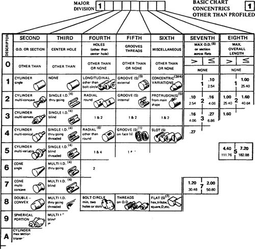
Figure 12.11 Workpart of Example 12.3. (Reprinted with permission from Ref. [11].)

Although these advantages exist in the GT machine cell, it is a matter of considerable inconvenience and disruption for the shop to make the conversion from a conventional process type layout (Figure 12.3) to the GT cell layout (Figure 12.4). This is surely one of the reasons group technology has not been more widely applied in the manufacturing industries. Today, many practitioners argue that it is possible to achieve a good share of the benefits of GT without physically rearranging the machines into cells. Notwithstanding these arguments, we consider in the current section some of the important aspects of group technology machine cells.
The composite part concept
Part families are defined by the fact that their members have similar design and manufacturing attributes. The composite part concept takes this part family definition to its logical conclusion. It conceives of a hypothetical part that represents all of the design and corresponding manufacturing attributes possessed by the various individuals in the family. Such a hypothetical part is illustrated in Figure 12.12. To produce one of the members of the part family, operations are added and deleted corresponding to the attributes of the particular part design. For example, the composite part in Figure 12.12 is a rotational part made up of seven separate design and manufacturing features. These features are listed in Table 12.2.
A machine cell would be designed to provide all seven machining capabilities. The machine, fixtures, and tools would be set up for efficient flow of work-parts through the cell. A part with all seven attributes, such as the composite part of Figure 12.12, would go through all seven processing steps. For part designs without all seven features, unneeded operations would simply be canceled.
In practice, the number of design and manufacturing attributes would be greater than seven, and allowances would have to be made for variations in overall
Figure 12.12 Composite part concept.
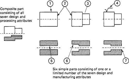
Table 12.2 Design and Manufacturing Attributes of the Composite Part in Figure 12.12

size and shape of parts in the part family. Nevertheless, the composite part concept is useful for visualizing the machine cell design problem.
Types of GT machine cells
The organization of machines into cells can follow one of three general patterns:
1. Single machine cell
2. Group machine layout
3. Flow line design
The single machine approach can be used for workparts whose attributes allow them to be made on basically one type of process, such as turning or milling. For example, the composite part of Figure 12.12 could be produced on a conventional turret lathe with the exception of the cylindrical grinding operation (operation 4 in Table 12.2). Even the grinding operation could be set up on the lathe with a little trouble.
The group machine layout is a cell design in which several machines are used together, with no provision for conveyorized parts movement between the machines. The cell contains the machines needed to produce a certain family of parts, and the machines are organized with the proper fixtures, tools, and operators to efficiently produce the parts family.
The flow line cell design is a group of machines connected by a conveyor system. Although this design approaches the efficiency of an automated transfer line, the limitation of the flow line layout is that all the parts in the family must be processed through the machines in the same sequence. Certain of the processing steps can be omitted, but the flow of work through the system must be in one direction. Reversal of work flow is accommodated in the more flexible group machine layout, but not conveniently in the flow line configuration. One possible
Figure 12.13 Flow line cell design.
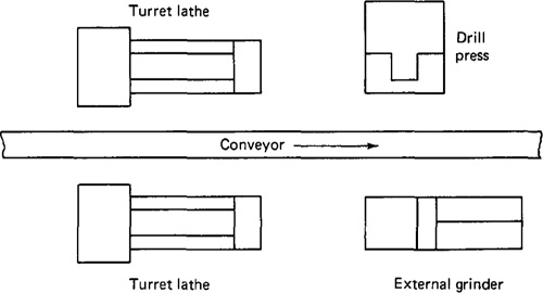
flow line cell design for producing the parts family of Figure 12.12 (the composite part) is illustrated in Figure 12.13.
12.6 Benefits of Group Technology
Although group technology is expected to be an important principle in future production plants, it has not yet achieved the widespread application which might be expected. There are several reasons for this. First, as we have already indicated, there is the problem of rearranging the machines in the plant into GT cells. Many companies have been inhibited from adopting group technology because of the expense and disruption associated with this transition to GT machine cells. Second, there is the problem of identifying part families among the many components produced in the plant. Usually associated with this problem is the expense of parts classification and coding. Not only is this procedure expensive, but it also requires a considerable investment in time and personnel resources. Managers often feel that these limited resources can better be allocated to other projects than group technology with its uncertain future benefits. Finally, it is common for companies to encounter a general resistance among its operating personnel when changeover to a new system is contemplated.
When these problems are solved and group technology is applied, the company will typically realize benefits in the following areas:
Product design
Tooling and setups
Materials handling
Production and inventory control
Employee satisfaction
Process planning procedures
Product design benefits
In the area of product design, improvements and benefits are derived from the use of a parts classification and coding system, together with a computerized design-retrieval system. When a new part design is required, the engineer or draftsman can devote a few minutes to figure the code of the required part. Then the existing part designs that match the code can be retrieved to see if one of them will serve the function desired. The few minutes spent searching the design file with the aid of the coding system may save several hours of the designer’s time. If the exact part design cannot be found, perhaps a small alteration of the existing design will satisfy the function. Use of the automated design-retrieval system helps to eliminate design duplication and proliferation of new part designs.
Other benefits of GT in design are that it improves cost estimating procedures and helps to promote design standardization. Design features such as inside corner radii, chamfers, and tolerances are more likely to become standardized with group technology. According to DeVries et al. [5], a 10% reduction in the number of drawings can be expected through standardization with GT.
Tooling and setups
Group technology also tends to promote standardization of several areas of manufacturing. Two of these areas are tooling and setups.
In tooling, an effort is made to design group jigs and fixtures that will accommodate every member of a parts family. Workholding devices are designed to use special adapters which convert the general fixture into one that can accept each part family member.
The machine tools in a GT cell do not require drastic changeovers in setup because of the similarity in the workparts processed on them. Hence, setup time is saved, and it becomes more feasible to try to process parts in an order so as to achieve a bare minimum of setup changeovers. It has been estimated that the use of group technology can result in a 69% reduction in setup time [5].
Materials handling
Another advantage in manufacturing is a reduction in the workpart move and waiting time. The group technology machine layouts lend themselves to efficient flow of materials through the shop. The contrast is sharpest when the flow line cell design is compared to the conventional process-type layout (Figures 1.3 and 1.4).
Production and inventory control
Several benefits accrue to a company’s production and inventory control function as a consequence of group technology.
Production scheduling is simplified with group technology. In effect, grouping of machines into cells reduces the number of production centers that must be scheduled. Grouping of parts into families reduces the complexity and size of the parts scheduling problem. And for those workparts that cannot be processed through any of the machine cells, more attention can be devoted to the control of these parts. Because of the reduced setups and more efficient materials handling with machine cells, production lead times, work-in-process, and late deliveries can all be reduced. Estimates on what can be expected are provided by DeVries et al. [5]:
70% reduction in production times
62% reduction in work-in-process inventories
82% reduction in overdue orders
Employee satisfaction
The machine cell often allows parts to be processed from raw material to finished state by a small group of workers. The workers are able to visualize their contributions to the firm more clearly. This tends to cultivate an improved worker attitude and a higher level of job satisfaction.
Another employee-related benefit of GT is that more attention tends to be given to product quality. Workpart quality is more easily traced to a particular machine cell in group technology. Consequently, workers are more responsible for the quality of work they accomplish. Traceability of part defects is sometimes very difficult in a conventional process-type layout, and quality control suffers as a result.
Process planning procedures
The time and cost of the process planning function can be reduced through standardization associated with group technology. A new part design is identified by its code number as belonging to a certain parts family, for which the general process routing is known. The logic of this procedure can be written into computer software to form a computer-automated process planning system. This topic will be discussed in detail in the following chapter.
References
[1] ABOU-ZEID, M. R., “Group Technology,” Industrial Engineering, May, 1975, pp. 32–39.
[2] THE BRISCH ORGANIZATION, The Modern Approach to Industrial Classification and Coding, Brisch, Birn ' Partners Ltd., Inc., Fort Lauderdale, Fla.
[3] BURBIDGE, J. L., The Introduction of Group Technology, Heinemann, London, 1975.
[4] DESAI, D. T., “Parts Coding Using Group Technology,” Industrial Engineering, November, 1981, pp. 78–86.
[5] DEVRIES, M. F., HARVEY, S. M., AND TIPNIS, V. A., Group Technology, Publication MDC 76-601, Machinability Data Center, Cincinnati, Ohio, 1976.
[6] GALLAGHER, C. C., AND KNIGHT, W. A., Group Technology, Butterworth ' Company Ltd., Kent, England, 1973.
[7] GROOVER, M. P., Automation, Production Systems, and Computer-Aided Manufacturing, Prentice-Hall, Inc., Englewood Cliffs, N.J., 1980, Chapter 18.
[8] HAM, I., “Introduction to Group Technology,” Technical Report MMR76-03, Society of Manufacturing Engineers, Dearborn, Mich., 1976.
[9] HOUTZEEL, A., Classification and Coding, TNO, Organization for Industrial Research, Inc., Waltham, Mass.
[10] HOUTZEEL, A., “The Many Faces of Group Technology,” American Machinist, January, 1979, pp. 115–120.
[11] MANUFACTURING DATA SYSTEMS, INC., CODE: The Parts Classification Data Retrieval System for Computer-Aided Manufacturing, Product Information PI-30-6000-0, 1977.
[12] OPITZ, H., A Classification System to Describe Workpieces, Pergamon Press Ltd., Oxford, England.
[13] OPRRZ, H., AND WIENDAHL, H. P., “Group Technology and Manufacturing Systems for Medium Quantity Production,” International Journal of Production Research, Vol. 9, No. 1, 1971, pp. 181–203.
[14] ORGANIZATION FOR INDUSTRIAL RESEARCH, Miclass, Migroup, Miplan, Migraphics (marketing brochure), Waltham, Mass.
[15] PHILLIPS, R. H., AND ELGOMAYEL, J., “Group Technology Applied to Product Design,” Educational Module Manufacturing Productivity Educational Committee, Purdue Research Foundation, West Lafayette, Inc., 1977.
[16] SCHAEFER, G. H., “Implementing CLM,” Special Report 736, American Machinist, August, 1981, pp. 151–174.
[17] STAUFFER, R. N:, “The Rewards of Classification and Coding,” Manufacturing Engineering, May, 1979, pp. 48–52.
[18] TNO, An Introduction to MICLASS, Organization for Industrial Research, Inc., Waltham, Mass.
Problems
12.1. Determine the form code (first five digits) in the Opitz system for the part shown in Figure 12.1. Assume the following dimensions for the part: Overall length = 2.5 in., large outside diameter (O.D.) = 2.2 in., small O.D. = 1.5 in., length of large O.D. = 1.0 in., hole diameter = 0.75 in.
12.2. Determine the form code (five digits) in the Opitz system for the composite part shown in Figure 12.12. Assume that the part is of the following dimensions: Length = 3.0 in., large O.D. = 2.375 in., small O.D. = 1.75 in., length of large diameter = 1.75 in., hole size = 0.5 in., counterbore diameter = 1.25 in., counterbore length = 1.25 in.; the thread is 13 UNC.
12.3. Develop a simple parts classification and coding scheme of no more than four digits which can be used to uniquely code the various possible combinations of part attributes for the composite part shown in Figure 12.12. The coding scheme should consider shape features and size, but not material. What is the structure of your coding scheme (hierarchical, chain-type, or hybrid)? What is the meaning of each digit in the code number? How many different values can each digit take? (Note: This problem will require a considerable amount of thought and deliberation and will probably require a significant amount of time to complete.)